Abstract
The traditional arc suppression device suffers from high costs and low utilization. These problems can be effectively avoided by using a hybrid multi-function arc suppression device (HMF-ASD). However, an HMF-ASD will consume active power during arc suppression. Based on this, a P-Q arc suppression method based on DC-link voltage stability is proposed. The energy flow during a single line-to-ground (SLG) fault is analyzed to optimize operation of the HMF-ASD. The topology and principle of the HMF-ASD are introduced. Secondly, the influence mechanism of the traditional arc suppression method on the output active power and energy flow direction of the HMF-ASD is analyzed. The internal reason for the change in the DC-link voltage is clarified. Additionally, non-fault phases of the HMF-ASD are regulated to produce no active output, delivering only the reactive current required for arc suppression. This method effectively mitigates SLG faults while maintaining DC-link voltage stability. Non-fault phases exclusively supply reactive power, with the active power needed for arc suppression drawn directly from the grid. The validity of the proposed method is confirmed through both simulation and experiment.
1. Introduction
A distribution network serves as a vital component in constructing a new power system. Characterized by complex structures and frequent grounding faults, the SLG fault accounts for the highest proportion, approximately 80% [1,2,3,4]. With the massive expansion of power electronic devices and nonlinear loads on distribution networks, both active and reactive power components in grounding fault currents have significantly increased [5,6]. The reactive power component can be only compensated by traditional passive arc suppression devices. Arcs can be generated by the active component and the harmonic component [7,8]. When an SLG fault occurs in a coal mine power grid in China, the active component of the measured grounding current reaches 13.05 A [8]. The fault current of some distribution networks is still as high as tens of amperes after the compensation capacitor component of the passive arc suppression device. If the fault cannot be eliminated, it will seriously threaten the power grid.
Literature Review
The active arc suppression device can achieve full compensation of the fault current. The existing active arc suppression devices inject zero-sequence current to regulate the zero-sequence voltage to be the opposite of the fault phase voltage [9,10,11]. However, these active arc suppression devices only operate during an SLG fault in distribution networks, suffering from low equipment utilization efficiency.
To fully leverage the flexible regulation capabilities of power electronic devices, an HMF-ASD that combines power quality management and grounding fault regulation is proposed. An HMF-ASD can not only achieve arc suppression during an SLG fault in the power grid but it also performs reactive power compensation, harmonic control, and three-phase imbalance control, which significantly enhances the equipment utilization rate. In [12], an HMF-ASD based on cascaded H-bridges is proposed, which outputs arc suppression current and reactive power compensation current.
However, the voltage withstand requirement of the HMF-ASD during arc suppression reaches the line voltage. This has led to the problem of high device costs. In [13], an HMF-ASD is introduced which integrates cascaded H-bridge configurations with a passive arc suppression coil. The primary function of the arc suppression coil is to offset the predominant reactive portion of the fault current. Meanwhile, the active module is designed to compensate for the active power component, harmonic distortions, and a residual fraction of the reactive power in the fault current. Since an HMF-ASD needs to fully compensate for the reactive power demands of the load, the overall capacity tends to be large. In [14], an HMF-ASD based on cascaded H-bridges and single-phase converters is proposed, which achieves deep integration of power exchange, power quality management, and grounding fault regulation. However, when the magnitude of the active current component is considerable, a voltage shift occurs at the common point, consequently compromising the DC-link voltage.
It is crucial for realizing efficient fault current compensation to maintain stable DC-link voltage. Till now, there are two ways for an HMF-ASD to maintain the DC-link voltage. Scheme I is controlling the converter to absorb energy based on positive and negative sequence loops [15,16,17,18,19,20]. Scheme II is adding additional energy storage units [21,22,23,24,25]. As for Scheme I, the influence of a zero sequence loop is not considered. Further, the existing DC-link voltage control strategies for an arc suppression device are not applicable to the condition with ground resistance [19,20]. As for Scheme II, in [21], every H-bridge module in the HMF-ASD is linked to an energy storage unit, leading to a relatively high overall device cost. In [22], only a single energy storage device is integrated into the HMF-ASD. In [23], a method is introduced that achieves DC-link voltage stability by alternately conducting arc suppression and voltage regulation on the two non-fault phases. However, this approach falls short in simultaneously accomplishing reactive power compensation and arc suppression. The existing HMF-ASDs effectively improve equipment utilization and practicality, but additional energy supply devices are needed [24,25].
To further solve the problem of unstable DC-link voltage in HMF-ASDs, a P-Q arc suppression method is proposed. Firstly, the topological structure of the HMF-ASD is elaborated in this paper. Under normal grid conditions, the HMF-ASD provides reactive power to meet the load’s demands. When an SLG fault occurs, reactive power compensation and arc suppression are achieved simultaneously. Secondly, the energy flow characteristics during an SLG fault and the reason for the failure of the traditional DC-link voltage control method are analyzed. Further, by controlling the HMF-ASD to output only reactive power during arc suppression, the DC-link voltage is stable. Finally, the validity of the proposed method is confirmed through both simulation and experiment.
2. Topology and Working Principle of HMF-ASD
The rated voltage of the distribution network is 10 kV and the neutral point is ungrounded. A three-phase structure with symmetrical distribution among the three phases is used, and the arc suppression coil is linked to the common point. The topology of the HMF-ASD is shown in Figure 1. In Figure 1, Ig, Ix (x = a, b, c), and Iinvx are the fault current, system current, and output current of the HMF-ASD, respectively. Ex, Usx, Ug, and Udc are the system voltage, busbar voltage, fault voltage, and DC-link voltage, respectively. rx and C0x are the ground resistance and capacitance, respectively. Cdc is the DC-link capacitance. Rf is the ground-fault resistance. Lf and LN are filter inductance and arc suppression inductance, respectively.
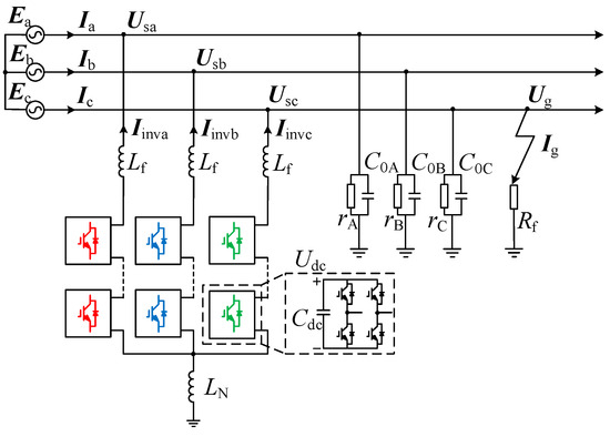
Figure 1.
Topology of the HMF-ASD.
2.1. Analysis of Reactive Power Compensation Mode
Under normal conditions of the power grid, the HMF-ASD operates in a reactive power compensation state. The HMF-ASD compensates reactive power by load, which can be regarded as a controlled current source. The equivalent circuit diagram during normal conditions of a power grid is shown in Figure 2.
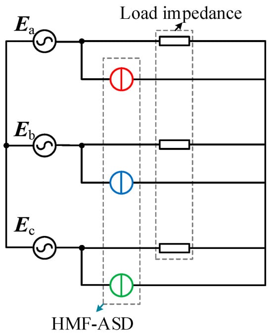
Figure 2.
Equivalent circuit diagram under normal conditions.
The voltage at the common connection point of the HMF-ASD Uo is regulated to 0 and the arc suppression inductance branch is equivalent to an open circuit. The HMF-ASD outputs reactive power compensation current and the HMF-ASD bears the phase voltage. The current flow diagram during normal operation of a power grid is shown in Figure 3.
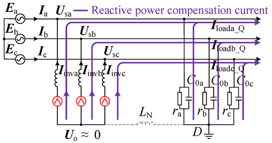
Figure 3.
Current flow diagram during normal operation of power grid.
The reactive power compensation current output by HMF-ASD is:
where Iloada_Q, Iloadb_Q, and Iloadc_Q are the reactive currents of the three-phase load.
2.2. Analysis of Arc Suppression Mode
When an SLG fault occurs, the HMF-ASD switches to arc suppression mode. The ground fault point establishes a closed loop with the grounding characteristics of the distribution network, allowing the ground current to pass through the fault location. During this process, arc suppression and reactive power compensation are carried out concurrently. The equivalent schematic diagram is shown in Figure 4 and the HMF-ASD can still be equivalently regarded as a controlled current source,
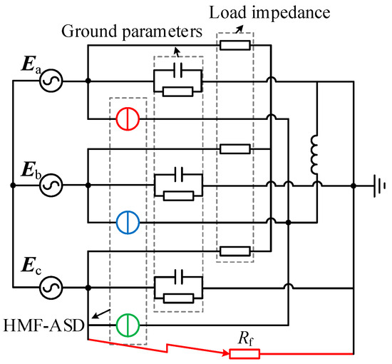
Figure 4.
Equivalent circuit diagram during SLG fault.
The current flow diagram during an SLG fault is shown in Figure 5 and Uo is controlled to −Ec. The HMF-ASD outputs arc suppression current to effectively reduce the current at the fault point.
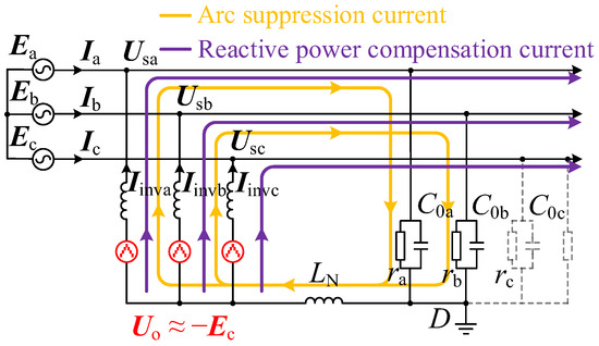
Figure 5.
Current flow diagram during SLG fault.
In order to obtain the arc suppression current of each phase output of the HMF-ASD, the current equation is written in the zero-sequence loop of the system. The following equation is obtained by formulating KCL at node D and substituting the network parameters:
Assuming that the three-phase voltage is balanced, the ground resistance and capacitance are r0 and C0, respectively. When using the traditional arc suppression method, the three-phase output arc suppression currents Iox output by the HMF-ASD are as follows:
The output currents of the HMF-ASD are as follows:
3. Failure Mechanism of Traditional Arc Suppression Method
This section examines how the conventional arc suppression approach affects the output active power and energy flow direction of the HMF-ASD, while also elucidating the underlying cause for variations in the DC-link voltage.
3.1. Power Characteristics of Traditional Arc Suppression Method
According to Figure 4 and Figure 5, it can be seen that the voltage borne by the active part of HMF-ASD Uinvx during arc suppression is as follows:
According to Equations (3)–(5), the active power transmitted by HMF-ASD Pinvx during arc suppression can be obtained as follows:
where θ is the angle between Ioa and Ea, which is related to rx and C0x. The specific expression is as follows:
The specific variation is shown in Table 1. It can be seen from Equation (6) that θ can directly reflect the range of the active power absorbed and emitted by the HMF-ASD.

Table 1.
Variation of energy of HMF-ASD with θ.
As can be seen from Table 1, when 0 ≤ θ ≤ 60°, Pinva > 0. Phase A consumes active power during arc suppression. When 0 ≤ θ < 30°, Pinvb > 0. Phase B consumes active power. When θ = 30°, Pinvb = 0. Phase B only transmits reactive power during arc suppression. When 30° < θ ≤ 60°, Pinvb < 0. The HMF-ASD absorbs active power during arc suppression. During arc suppression, Pinvc = 0, and phase C only outputs the load reactive current.
3.2. Control Strategy of the Traditional Arc Suppression Method
The reference value id.dc corresponding to the voltage loop is obtained by calculating the difference between the reference value Udc.ref and the actual value Udc through the voltage loop PI. The load current is sampled, and the reactive compensation reference current iq.ref is subsequently calculated following dq transformation. The grid voltage components along the D-axis and Q-axis are combined with the controller outputs to produce the corresponding D-axis and Q-axis reference signals. The total arc suppression current Iz specified in Formula (3) is utilized as the reference value. The specific expression of Iz is Iz = Ioa + Iob + Ioc. Additionally, the reference signal for the 0-axis is obtained by processing the difference in the zero-sequence current io through the current loop PI controller. Finally, the modulated signal Usum is produced by performing an inverse dq transformation. The traditional arc suppression method is shown in Figure 6.
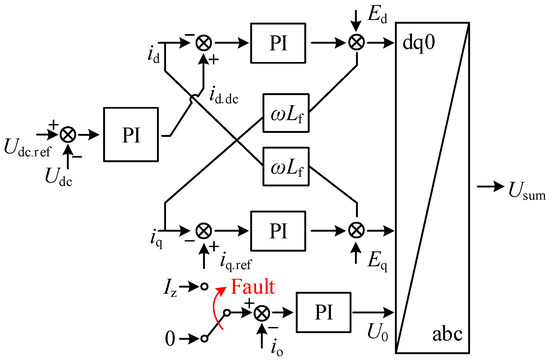
Figure 6.
Control strategy of the traditional arc suppression method.
To compensate for the active power consumed during arc suppression and sustain DC-link voltage stability in the HMF-ASD, the system absorbs active power from the grid using a conventional arc suppression strategy. The active components of both the arc suppression current and the stabilizing current exhibit equal magnitudes but opposite polarities. Based on Equations (3)–(5), the stabilizing current of the HMF-ASD Iox1 can be expressed as follows:
where Iox1 is the active component of the stabilizing current of the HMF-ASD.
The conventional arc suppression approach is limited to regulating only the active power exchanged between the HMF-ASD and the distribution network. According to Equation (8), it is known that Ioa1 + Iob1 + Ioc1 = 0. At this time, the neutral point of the grid cannot satisfy KCL. There must be reactive power exchange between the HMF-ASD and the grid. Therefore, the traditional arc suppression method is unable to stabilize DC-link side voltage.
4. P-Q Arc Suppression Method Based on DC-Link Voltage Stability
Due to the large ground resistance, the active component of the arc suppression current only accounts for 5–10%. The variation range of α is from 0° to 10°, and the specific variation trajectory is shown in Figure 7a. As shown in the figure, the solid line and the dotted line represent the phasor relationship when α = 10° and α = 0°, respectively. The change trajectory is shown in the gray line.
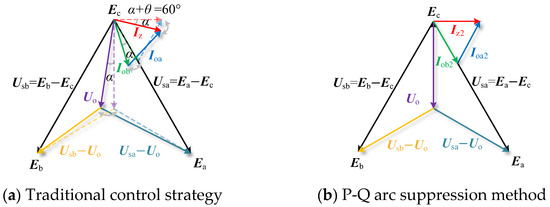
Figure 7.
Phasor diagram of HMF-ASD.
To address the aforementioned issues, a P-Q arc suppression method is introduced. During an SLG fault, the HMF-ASD is controlled to output only reactive power, enabling complete compensation of the fault current and stabilization of the DC-link voltage without using external power supply devices. When the SLG fault occurs, non-fault phases jointly output arc suppression current. The phasor relationship is shown in Figure 7b, where α is the angle between the rx and C0x. The specific expression is as follows:
According to Figure 7, the zero-sequence power output by the HMF-ASD is as follows:
where Pzab and Qzab are the zero-sequence active power and reactive power using the traditional arc suppression method, respectively.
When the traditional arc suppression method is adopted, the HMF-ASD is required to simultaneously output both active and reactive power. To stabilize the DC-link voltage, supplementary energy supply units become necessary. The P-Q arc suppression method can attain complete compensation of the fault current and ensure the stability of the DC-link voltage by regulating the HMF-ASD to output solely reactive power, thereby eliminating the need for additional energy supply devices. Since the active and reactive components of the arc suppression current are respectively provided by the power grid and the HMF-ASD, the value of the arc suppression current remains unchanged. The value of the arc suppression current will not be affected by the HMF-ASD.
The zero-sequence power of the HMF-ASD is as follows:
where P′zab and Q′zab are the zero-sequence active power and reactive power using the P-Q arc suppression method, respectively.
Therefore, when the P-Q arc suppression method is adopted, the phase A and phase B of the HMF-ASD compensate the zero-sequence reactive power. Meanwhile, the grid side undertakes the compensation for the active power. Both active power and reactive power flow along the line. The diagram illustrating the zero-sequence power flow is shown in Figure 8.
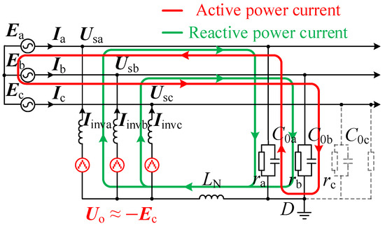
Figure 8.
Zero-sequence power flow diagram of P-Q arc suppression method.
The proposed control strategy is shown in Figure 9. The control strategy of the HMF-ASD mainly includes a power loop and a voltage stability loop. Qb* and Qa* are the reactive power reference values of phase B and A, respectively. Qb and Qa are the actual reactive power values of phase B and A, respectively. izb and iza are the current reference values corresponding to the power loops of phase B and A, respectively. idcb and idca are the current reference values corresponding to the voltage stabilizing loops of phase B and A, respectively. Ebc and Eac are the line voltage of the BC phase and the AC phase, respectively. Udcx.ref and ∑Udcxi are the reference values of the actual value of the DC-link voltage. N is the number of cascades.
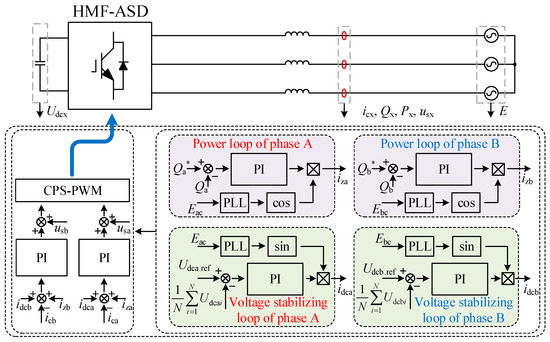
Figure 9.
Control strategy of HMF-ASD.
- (1)
- Power loop
During the fault, the Qa* and Qb* needed for arc suppression in phases A and B are calculated, and the reference values of arc suppression currents iza and izb are obtained through the power loop PI using the difference between them and the actual value.
- (2)
- Voltage stabilizing loop
idca and idcb of the voltage stabilizing are obtained through the voltage stabilizing PI. The actual output current is regulated by calculating the deviation between the combined current references and the measured current.
- (3)
- Current loop
iza, izb, idca, and idcb serve as the input to the current loop PI regulator, whose output is superimposed on the busbar voltage of the HMF-ASD. The resulting signal undergoes carrier phase shift PWM (CPS-PWM) to generate the signals for the HMF-ASD.
Till now, two ways are proposed to stabilize the DC-link voltage in an HMF-ASD. Scheme I is controlling the converter to absorb energy based on positive and negative sequence loops. Scheme II is adding auxiliary DC power supply units.
- (1)
- As for Scheme I, the influence of a zero sequence loop is not considered. Further, the existing DC-link voltage control strategies for arc suppression devices are not applicable to the condition with ground resistance. As the DC-link voltage of the HMF-ASD progressively decreases, fault current escalates, ultimately compromising arc suppression capability.
- (2)
- As for Scheme II, the DC side of the HMF-ASD is connected to auxiliary DC power supplies to provide arc suppression energy. While this method enables complete fault current compensation with minimal control complexity, it incurs relatively high costs.
- (3)
- To achieve DC-link voltage stability and full fault current compensation without auxiliary power supplies, this paper introduces a P-Q-based arc suppression strategy. A comparative analysis with existing methods is presented in Table 2. The proposed method demonstrates superior cost-effectiveness and arc suppression performance compared to conventional approaches, though its control complexity exceeds that of Scheme II.
Table 2. The comparison between existing methods and P-Q arc suppression method.
5. Simulation Results
To evaluate the practicality and performance of the proposed HMF-ASD topology and its operational functions, a simulation model is developed using the MATLAB 2021a/Simulink environment. Detailed simulation parameters are provided in Table 3.
Table 3.
Simulation Parameters.
5.1. Simulation of Reactive Power Compensation Mode
During 0–0.1 s, the HMF-ASD is not put into operation. During 0.1–0.5 s, the HMF-ASD operates in reactive power compensation mode. Comprehensive simulation waveforms for the reactive power compensation mode are provided in Figure 10. Ea and Ia waveforms are shown in Figure 10a. Ea = 8165 V and Ia = 173 A. The in-phase alignment of voltage and current confirms the system’s effective reactive power compensation capability. The reactive power distribution is further analyzed in Figure 10b, showing the load reactive power (Qload = 241 kVar), the reactive power of the ground capacitance (Qc = 105 kVar), and the reactive power of the HMF-ASD (Qinv = 136 kVar). The ground capacitance accounts for 43.6% of the total compensation, while the HMF-ASD contributes 56.4%.
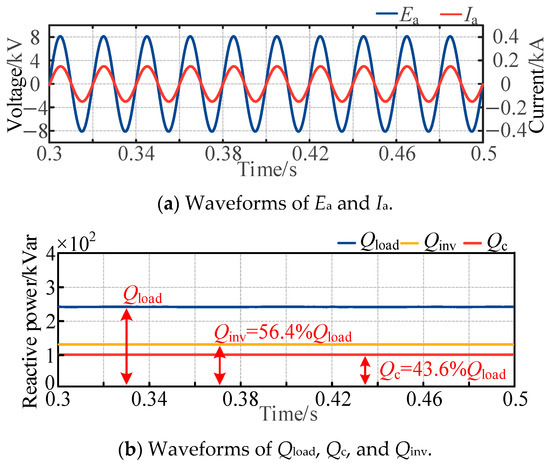
Figure 10.
Simulation waveforms of reactive power compensation mode.
5.2. Simulation of Arc Suppression Mode
In order to further verify the performance of the HMF-ASD using the traditional control strategy, a simulation model of a 10 kV distribution network is built. The waveforms using the traditional control strategy are shown in Figure 11a,b. The HMF-ASD operates in arc suppression mode from 0.3–0.5 s, switching to reactive power compensation mode during other times.
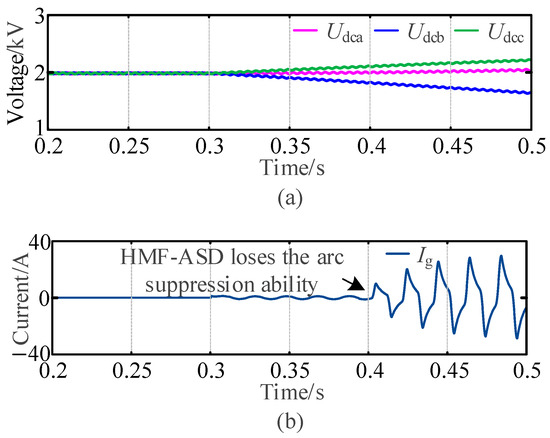
Figure 11.
Simulation waveforms of arc suppression mode using traditional control strategy. (a) Waveforms of Udca, Udcb, and Udcc. (b) Waveforms of Ig.
As shown in Figure 11a, the DC-link voltage of the CHB remains stable at 2000 V between 0.2 s and 0.3 s. At 0.3 s, non-fault phases initiate arc suppression current injection. During this period, phase B consumes active power, causing its DC-link voltage to decrease, while phase C absorbs active power, resulting in an increase in its CHB DC-link voltage. Figure 11b demonstrates that the HMF-ASD achieves effective arc suppression between 0.3 s and 0.4 s. However, as DC-link voltages continue to decline, the fault current rises, ultimately compromising the HMF-ASD arc suppression capability. These findings indicate that the conventional control strategy fails to maintain effective arc suppression under conditions involving ground resistance.
The simulated waveforms of the HMF-ASD using the P-Q arc suppression method are presented in Figure 12. For fault resistances Rf = 1 Ω and Rf = 1000 Ω, the corresponding fault current Ig waveforms are displayed in Figure 12a,b. After the HMF-ASD is switched to the arc suppression mode, the fault current Ig is reduced to zero within 100 ms. The DC-link voltages of phases B and C, as shown in Figure 12c,d, stabilize near 2 kV for each sub-module after mode transition, ensuring precise delivery of arc suppression current. The output currents (Iinva, Iinvb, and Iinvc) are illustrated in Figure 12e. During reactive power compensation mode, the system accurately injects compensation current, while in arc suppression mode, phases B and C deliver 73.7∠-30.8° A and 75.1∠-149.6° A, respectively, enabling effective SLG fault mitigation.
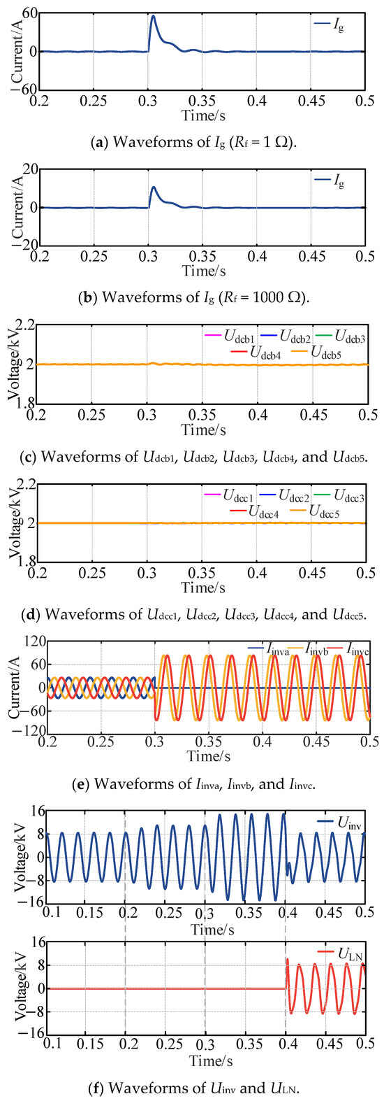
Figure 12.
Simulation waveforms of arc suppression mode using P-Q arc suppression method.
To assess the impact of arc suppression inductance, the HMF-ASD operates without current injection during 0.2–0.3 s. From 0.3–0.4 s, direct grounding is employed to inject arc suppression current, followed by inductance-based grounding from 0.4–0.5 s. The voltage waveforms for the HMF-ASD and arc suppression inductance are depicted in Figure 12f. Under normal grid conditions, the HMF-ASD output voltage matches the phase voltage. At 0.2 s, an SLG fault in phase A causes neutral point voltage deviation, elevating the HMF-ASD output above the phase voltage. Direct grounding at 0.3 s shifts the neutral point voltage to approximately −Ea, raising the HMF-ASD output to line voltage. At 0.4 s, inductance-based grounding reduces the inductance voltage ULN to near −Ea, restoring the HMF-ASD output to phase voltage. Simulation results confirm that inductance-based grounding significantly decreases inductor capacity requirements in arc suppression mode, thereby minimizing power device usage.
6. Experimental Results
To validate the effectiveness and precision of the proposed P-Q arc suppression method, an experimental assessment is conducted using a Control Hardware-in-the-Loop (CHIL) testbed built on the RT-LAB OP5600 platform (Opal-RT). Figure 13 illustrates the configuration of this RT-LAB-based CHIL testing system.
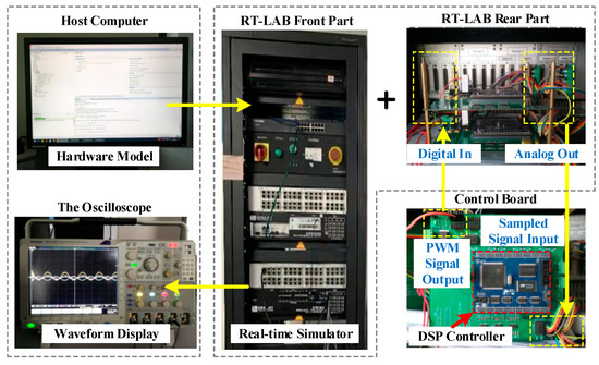
Figure 13.
RT-LAB based CHIL testing platform.
An SLG fault is assumed to occur in Phase A at t1. During the t0-t1, the HMF-ASD operates in reactive power compensation mode. From t1-t2, the system transitions to arc suppression mode, and after t2, it reverts to reactive power compensation. All other experimental parameters remain consistent with those used in the simulation.
Figure 14 displays the experimental waveforms of Udca, Udcb, and Udcc. Using the proposed P-Q arc suppression method, the DC-link voltage of the HMF-ASD remains stable at 2000 V during arc suppression, with voltage fluctuations constrained within 50 V. Figure 15 presents the experimental waveforms of Eb and Ib. When the HMF-ASD operates in reactive power compensation mode, it supplies the load’s reactive power demand, ensuring in-phase alignment between grid voltage and current. Figure 16 illustrates the experimental waveforms of Uo, ULN, and Ig. During arc suppression mode, the HMF-ASD reduces the fault current to 0.1 A, while the voltage across the arc suppression inductance reaches approximately 8000 V. Figure 17 shows the experimental waveforms of Iinva, Iinvb, and Iinvc. The reactive current required for reactive power compensation is delivered in compensation mode, whereas the reactive current for arc suppression is provided in suppression mode.
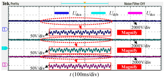
Figure 14.
Experimental waveforms of Udca, Udcb, and Udcc.
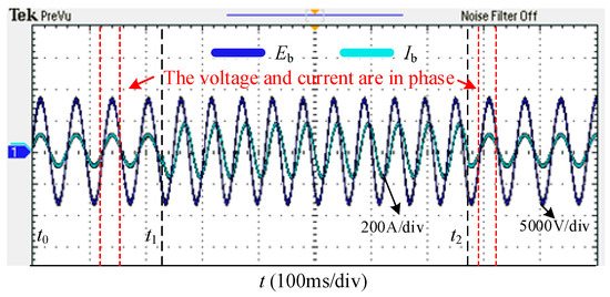
Figure 15.
Experimental waveforms of Eb and Ib.
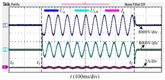
Figure 16.
Experimental waveforms of Uo, ULN, and Ig.
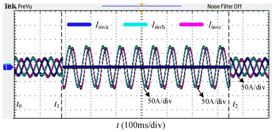
Figure 17.
Experimental waveforms of Iinva, Iinvb, and Iinvc.
7. Conclusions
Aiming at the problem that HMF-ASDs need to add additional power supply units to maintain DC-link voltage, a P-Q arc suppression method based on DC-link voltage stability is proposed. The conclusions are as follows:
- (1)
- The working principle of the HMF-ASD is introduced and the current flow of the HMF-ASD in two modes is analyzed.
- (2)
- The influence mechanism of the traditional arc suppression method on the output active power and energy flow direction of the HMF-ASD is analyzed. The internal causes of DC link voltage changes are clarified.
- (3)
- The phase relationship between voltage and current under arc suppression mode is analyzed, and a P-Q arc suppression method is proposed. By controlling the HMF-ASD to compensate only zero-sequence reactive power, the HMF-ASD can stabilize the DC-link voltage.
- (4)
- Compared with existing methods, the proposed method has lower cost and better arc suppression effect, but the control complexity is relatively high.
- (5)
- In the future, the performance improvement of PLL under unbalanced and fault conditions will be further studied.
Author Contributions
Supervision, Q.G.; conceptualization, Z.H. and Q.G.; methodology, Z.H. and H.L.; software, H.L. and C.Z.; validation, J.Y.; project administration, Q.G.; formal analysis, H.L. and C.Z.; investigation, J.Y.; resources, C.Z.; data curation, H.L.; writing—original draft, Z.H.; writing—review and editing, Z.H. and H.L.; visualization, C.Z. and J.Y.; funding acquisition, H.L. All authors have read and agreed to the published version of the manuscript.
Funding
This research was funded by the Science and Technology Project of China Southern Power Grid Corporation, grant number 0562002023030301PD00015.
Data Availability Statement
Data is contained within the article.
Conflicts of Interest
Authors Hongwen Liu, Chunli Zhang and Jindong Yang were employed by the Yunnan Power Grid Co., Ltd. The remaining authors declare that the research was conducted in the absence of any commercial or financial relationships that could be construed as a potential conflict of interest.
Nomenclature
| Parameters | Definitions |
| Ex | System voltage |
| Usx | Busbar voltage |
| Ug | Fault voltage |
| Uo | The voltage at the common point of HMF-ASD |
| Uinvx | The voltage borne by the active part of HMF-ASD |
| Ix | System current |
| Ig | Fault current |
| Iinvx | Output current of HMF-ASD |
| Iloadx_Q | Reactive currents of the load |
| Iox | Arc suppression currents |
| Iox1 | The active component of the stabilizing current of HMF-ASD |
| Iz | Total arc suppression current |
| rx | The ground resistance |
| C0x | The ground capacitance |
| Cdc | The DC-link capacitance |
| Lf | Filter inductance |
| LN | Arc suppression inductance |
| Rf | The ground-fault resistance |
| Pinvx | The active power transmitted by HMF-ASD |
| Pzab | The zero-sequence active power using traditional arc suppression method |
| Pzab′ | The zero-sequence active power using P-Q arc suppression method |
| Qx* | The reactive power reference values |
| Qx | The actual reactive power values |
| Qload | The reactive power of the load |
| Qc | The reactive power of the ground capacitance |
| Qinv | The reactive power of HMF-ASD |
| Qzab | The zero-sequence reactive power using traditional arc suppression method |
| Qzab′ | The zero-sequence reactive power using P-Q arc suppression method |
| izx | The current reference values corresponding to power loops |
| idcx | The current reference values corresponding to voltage stabilizing loops |
| N | The number of cascades |
| Udcx.ref | The reference value of DC-link voltage |
| ∑Udcxi | The actual value of DC-link voltage |
| ULN | The voltage of arc suppression inductance |
| α | The angle between the ground resistance and capacitance |
References
- Zhu, R.; Liserre, M. Control of Smart Transformer Under Single-Phase to Ground Fault Condition. IEEE Trans. Power Electron. 2020, 35, 2034–2043. [Google Scholar] [CrossRef]
- Huang, Z.; Guo, Q.; Xiao, Z.; Tu, C.; Sun, K.; Wang, L.; Zhu, D.; Hou, Y. Hybrid Multifunctional Arc Suppression Inverter With Its Steady and Transient State Operation Optimization Method. IEEE Trans. Power Electron. 2025, 40, 10313–10323. [Google Scholar] [CrossRef]
- Tang, J.; Xiong, B.; Li, Y.; Yuan, C.; Qiu, Y. Faulted Feeder Identification Based on Active Adjustment of Arc Suppression Coil and Similarity Measure of Zero-Sequence Currents. IEEE Trans. Power Deliv. 2021, 36, 3903–3913. [Google Scholar] [CrossRef]
- Liu, K.; Zhang, S.; Li, B.; Zhang, C.; Liu, B.; Jin, H.; Zhao, J. Flexible Grounding System for Single-Phase to Ground Faults in Distribution Networks: A Systematic Review of Developments. IEEE Trans. Power Deliv. 2022, 37, 1640–1649. [Google Scholar] [CrossRef]
- Li, L.; Zeng, X.; Bai, H.; Yu, K.; Li, J.; Peng, H.; Wang, Z.; Luo, H.; Wang, F. Analysis and Design of Flexible Arc Suppression Device Based on Proportional Series Lagging Control. Int. J. Electr. Power Energy Syst. 2022, 143, 108478. [Google Scholar] [CrossRef]
- Tan, L.; Wang, Y.; Yin, X.; Qiao, J.; Xu, W. Injected Current Regulation Based Stator Ground Fault Arc Suppression Method for Large Hydro-Generators. Int. J. Electr. Power Energy Syst. 2022, 143, 108513. [Google Scholar] [CrossRef]
- Belik, M.; Kuchanskyy, V.; Rubanenko, O. The Method of the Secondary Arc Suppression in Cycle Single-Phase Auto Reclose with High-Level Penetration Renewable Energy Sources. Energies 2023, 16, 6880. [Google Scholar] [CrossRef]
- Ouyang, S.; Liu, J.; Yang, Y.; Chen, X.; Song, S.; Wu, H. Control Strategy for Arc-Suppression-Coil-Grounded Star-Connected Power Electronic Transformers. IEEE Trans. Power Electron. 2019, 34, 5294–5311. [Google Scholar] [CrossRef]
- Wang, W.; Gao, X.; Fan, B.; Zeng, X.; Yao, G. Faulty Phase Detection Method under Single-Line-to-Ground Fault Considering Distributed Parameters Asymmetry and Line Impedance in Distribution Networks. IEEE Trans. Power Deliv. 2022, 37, 1513–1522. [Google Scholar] [CrossRef]
- Zeng, X.; Xu, Y.; Wang, Y. Some Novel Techniques for Insulation Parameters Measurement and Petersen-Coil Control in Distribution Systems. IEEE Trans. Ind. Electron. 2010, 57, 1445–1451. [Google Scholar] [CrossRef]
- Fan, B.; Yao, G.; Yu, K.; Zeng, X.; Wang, W.; Zhuo, C.; Guerrero, J. Principle of Flexible Ground-Fault Arc Suppression Device Based on Zero-Sequence Voltage Regulation. IEEE Access 2021, 9, 2382–2389. [Google Scholar] [CrossRef]
- Zheng, Z.; Guo, M.; Yang, N.; Jin, T. Flexible Arc-Suppression Method Based on Improved Distributed Commutations Modulation for Distribution Networks. Int. J. Electr. Power Energy Syst. 2020, 116, 105580. [Google Scholar] [CrossRef]
- Zhou, X.; Lu, S. An Arc-Suppression Method Based on the Coordinated Operation of the Petersen Coil and the Static Synchronous Compensator in Distribution Networks. Trans. China Electr. Soc. 2019, 34, 1251–1262. [Google Scholar]
- You, J.; Guo, M. Integrated Converter with Reactive Power Compensation and Fault Suppression and Its Control Strategy. Power Syst. Technol. 2022, 46, 2241–2248. [Google Scholar]
- Koyama, Y.; Nakazawa, Y.; Mochikawa, H.; Kuzumaki, A.; Sano, K.; Okada, N. A Transformerless 6.6-kV STATCOM Based on a Hybrid Cascade Multilevel Converter Using SiC Devices. IEEE Trans. Power Electron. 2018, 33, 7411–7423. [Google Scholar] [CrossRef]
- Wang, H.; Zhang, J.; Xia, X.; Gao, F.; Cheng, J. DC-Link Capacitance Design for Cascaded H-Bridge STATCOM With Sum of Squares Formulation. IEEE Trans. Power Electron. 2024, 39, 5733–5749. [Google Scholar] [CrossRef]
- Zhao, G.; Guo, M.; Zhang, B.; Zheng, Z.; Hong, Q. Cascaded H-Bridge Converter-Based Flexible Arc Suppression Method Adapting to Line Parameter Variations. IEEE Trans. Power Electron. 2025, 40, 11809–11819. [Google Scholar] [CrossRef]
- Pang, R.; Ding, W. Series Arc Fault Characteristics and Detection Method of a Photovoltaic System. Energies 2023, 16, 8016. [Google Scholar] [CrossRef]
- Cong, H.; Wang, Y.; Hu, X.; Zhang, X.; Su, W.; Li, Q. Simulation Study on the Suppression Effect on Secondary Arcs Based on Online Injection Power Compensation. IEEE Trans. Power Deliv. 2025, 40, 878–888. [Google Scholar] [CrossRef]
- Guo, C.; Guo, M. Quasi-PR Control Based Flexible Arc Suppression Method in Power Distribution Networks. In Proceedings of the 2020 IEEE 1st China International Youth Conference on Electrical Engineering (CIYCEE), Wuhan, China, 1–4 November 2020; pp. 1–7. [Google Scholar]
- Qiu, W.; Guo, M.; Yang, G.; Zheng, Z. Model-Predictive-Control-Based Flexible Arc-Suppression Method for Earth Fault in Distribution Networks. IEEE Access 2019, 7, 16051–16065. [Google Scholar] [CrossRef]
- Huang, Z.; Guo, Q.; Tu, C.; Hou, Y.; Jiang, F.; Wang, X.; Xiao, F.; Xiao, Z. A Non-neutral Alternate Arc Suppression Method for Single Phase Grounding Fault in Active Distribution Network. Int. J. Electr. Power Energy Syst. 2023, 152, 109182. [Google Scholar] [CrossRef]
- Chen, Y.; Lu, S.; Zhou, X.; Liang, S. Two-Phase Current Injection Method for Single Line-to-Ground Fault Arc-Suppression with Revised STATCOM. IEEE Access. 2020, 8, 188299–188308. [Google Scholar] [CrossRef]
- Hou, Y.; Guo, Q.; Tu, C.; Jiang, F.; Wang, L.; Wang, X. Adaptive Active Voltage-Type Arc Suppression Strategy Considering the Influence of Line Parameters in Active Distribution Network. IEEE Trans. Ind. Electron. 2023, 70, 4799–4808. [Google Scholar] [CrossRef]
- Bains, T.P.S.; Sidhu, T.S.; Xu, Z.; Voloh, I.; Zadeh, M.R.D. Impedance-Based Fault Location Algorithm for Ground Faults in Series-Capacitor-Compensated Transmission Lines. IEEE Trans. Power Deliv. 2018, 33, 189–199. [Google Scholar] [CrossRef]
Disclaimer/Publisher’s Note: The statements, opinions and data contained in all publications are solely those of the individual author(s) and contributor(s) and not of MDPI and/or the editor(s). MDPI and/or the editor(s) disclaim responsibility for any injury to people or property resulting from any ideas, methods, instructions or products referred to in the content. |
© 2025 by the authors. Licensee MDPI, Basel, Switzerland. This article is an open access article distributed under the terms and conditions of the Creative Commons Attribution (CC BY) license (https://creativecommons.org/licenses/by/4.0/).