
Experimental and Simulation-Based Development of Heat-Transfer Correlations for Cyclopentane PCHE


Abstract
1. Introduction
2. Theory and Methods
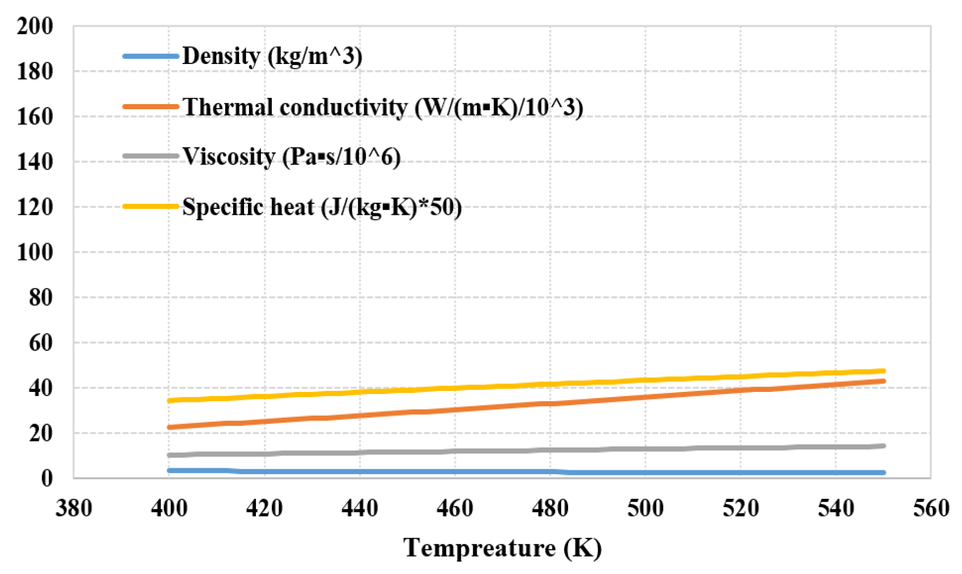
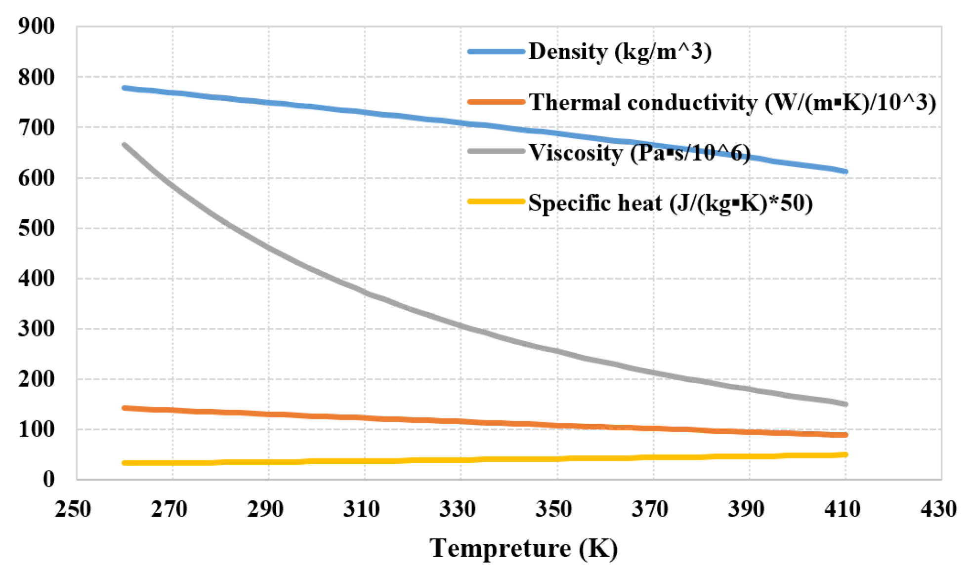
2.1. Thermodynamic Properties of Cyclopentane as a Working Fluid
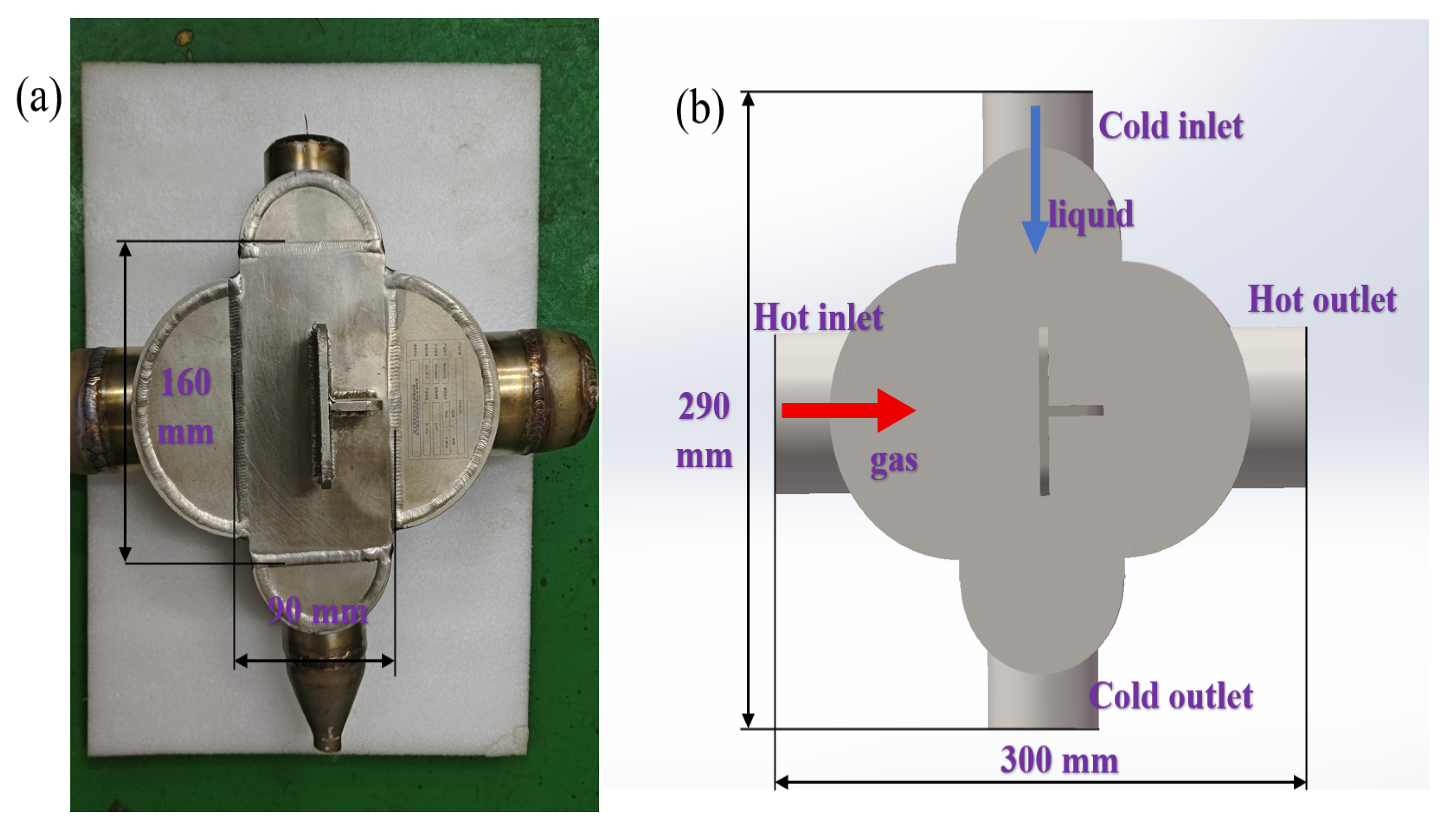
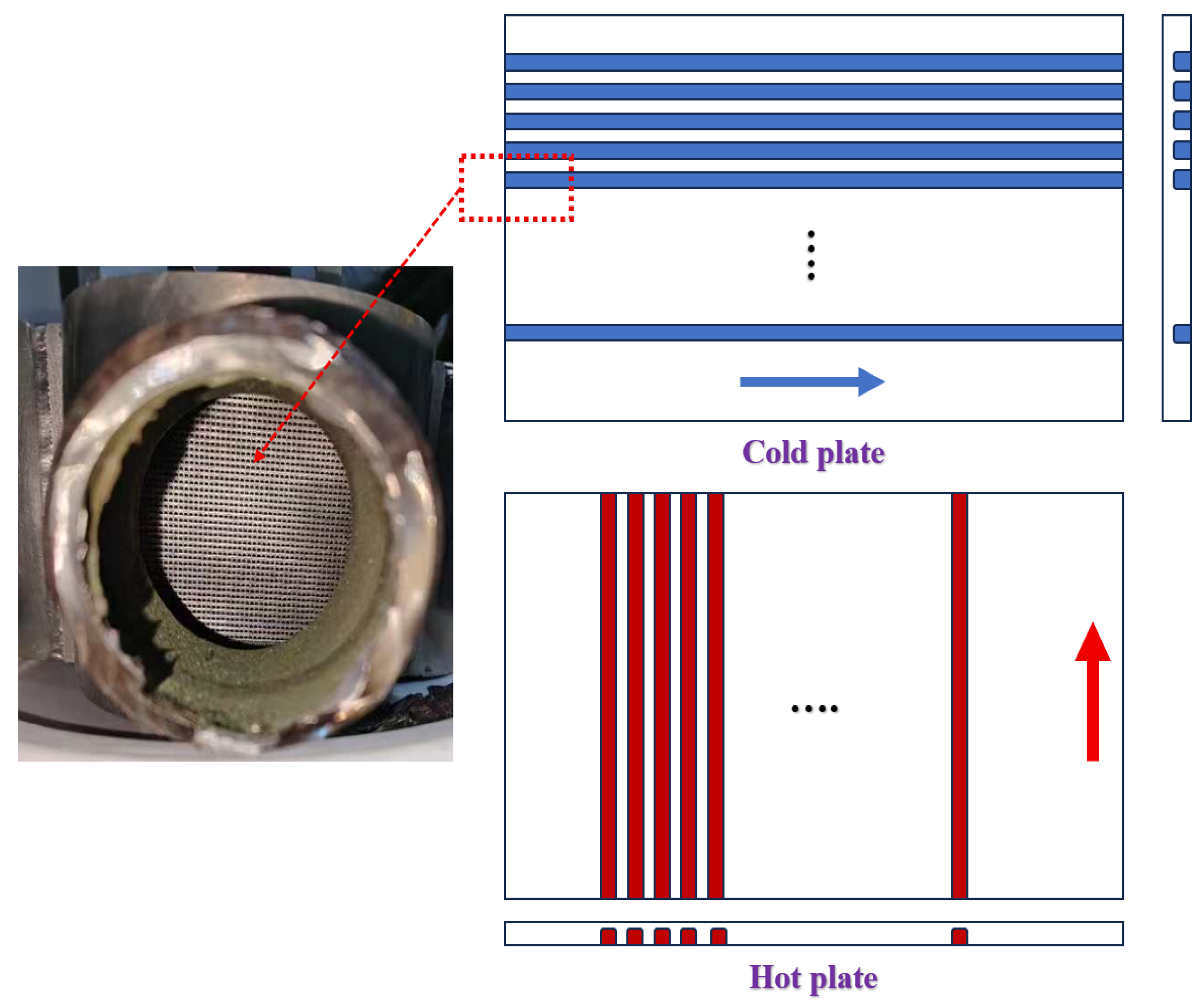
2.2. Design of the Printed-Circuit Heat Exchanger
2.3. Experimental Method
2.4. CFD Fluent Simulation Method
3. Experimental Results and Analysis
3.1. Heat-Transfer Performance Analysis
3.2. Pressure-Drop Performance Analysis
4. Simulation Results and Analysis
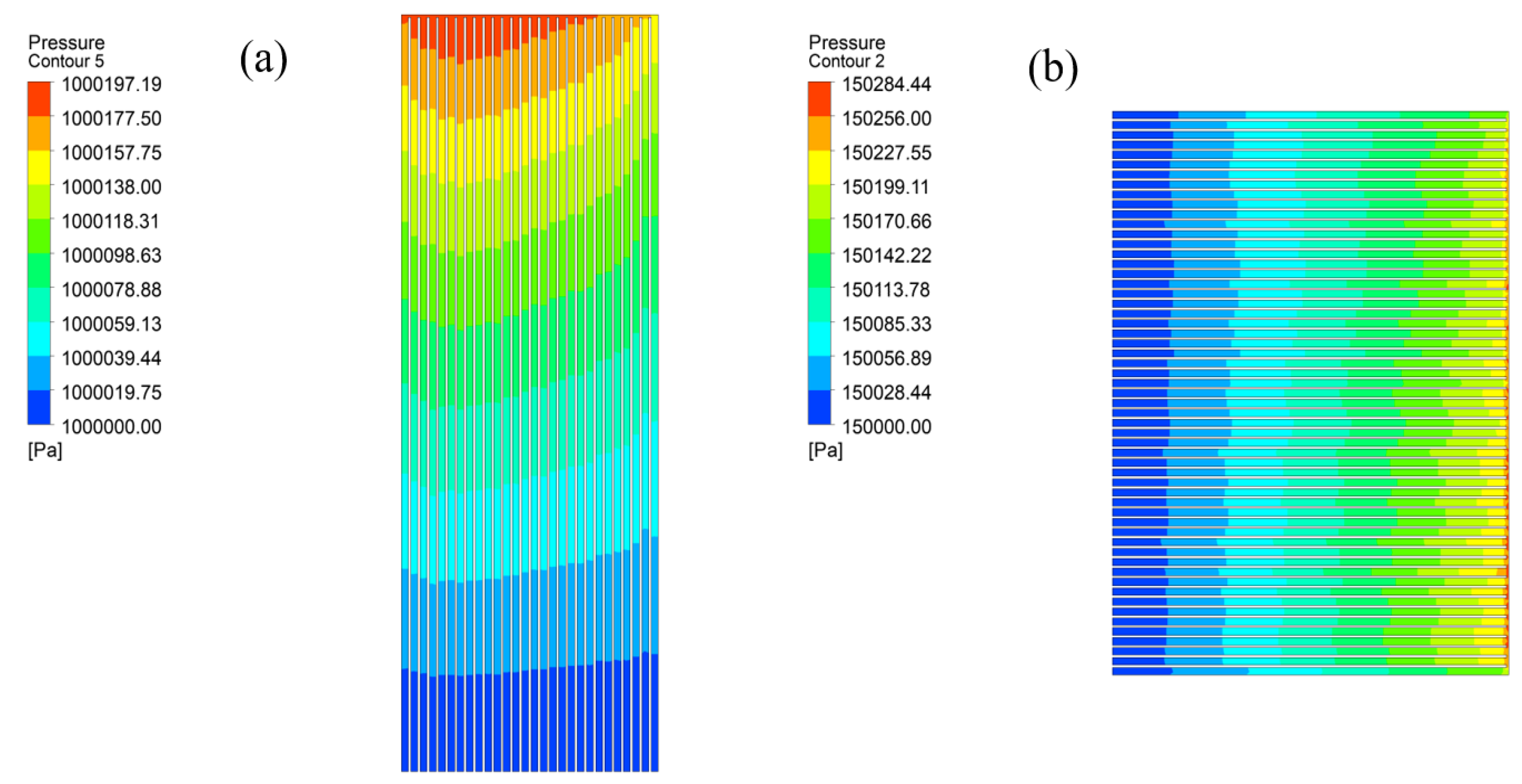
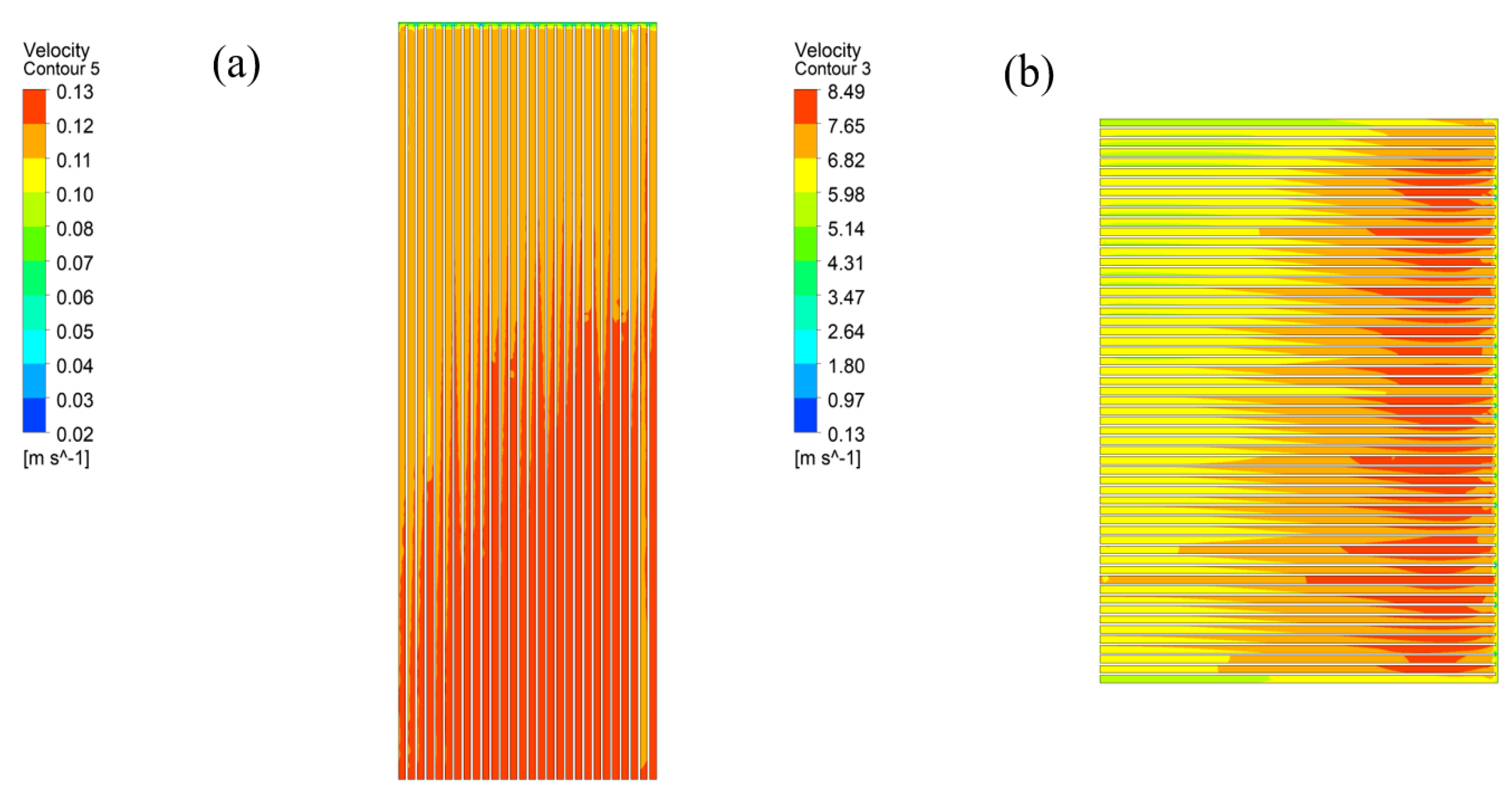
4.1. Temperature Field and Pressure Field Analysis
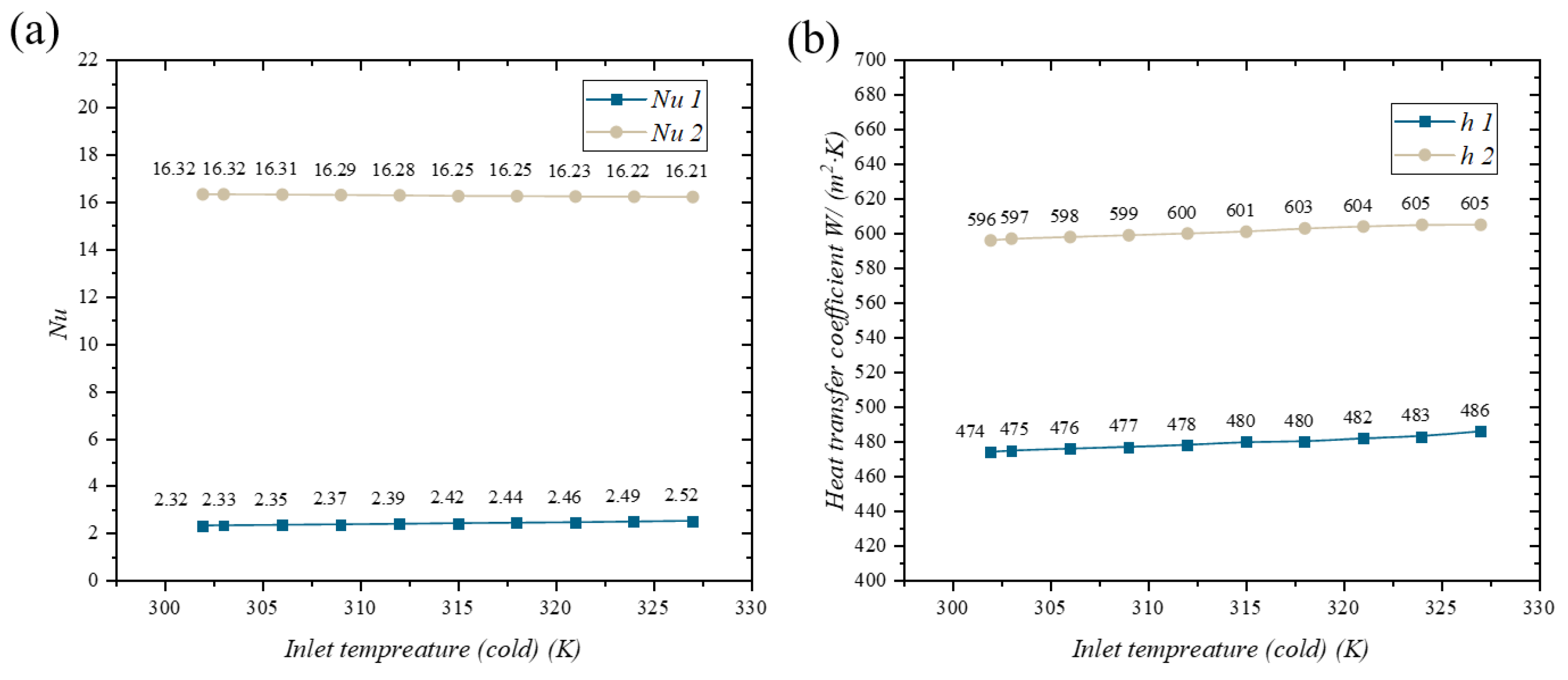
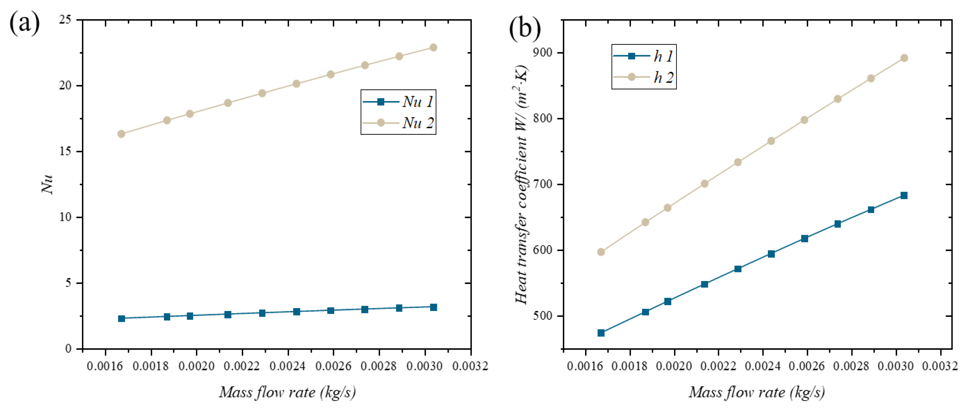
4.2. Heat-Transfer Performance Evaluation
5. Derivation and Verification of Heat-Transfer Correlations
5.1. Derivation of Heat-Transfer Correlations
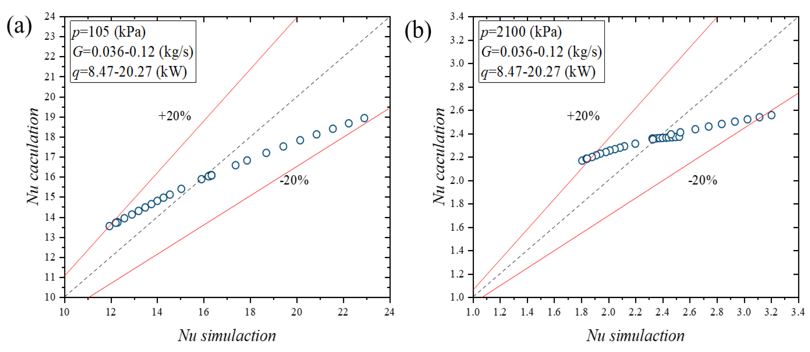
5.2. Prediction Accuracy of High-Precision Heat-Transfer Correlations for the Hot and Cold Sides
6. Conclusions
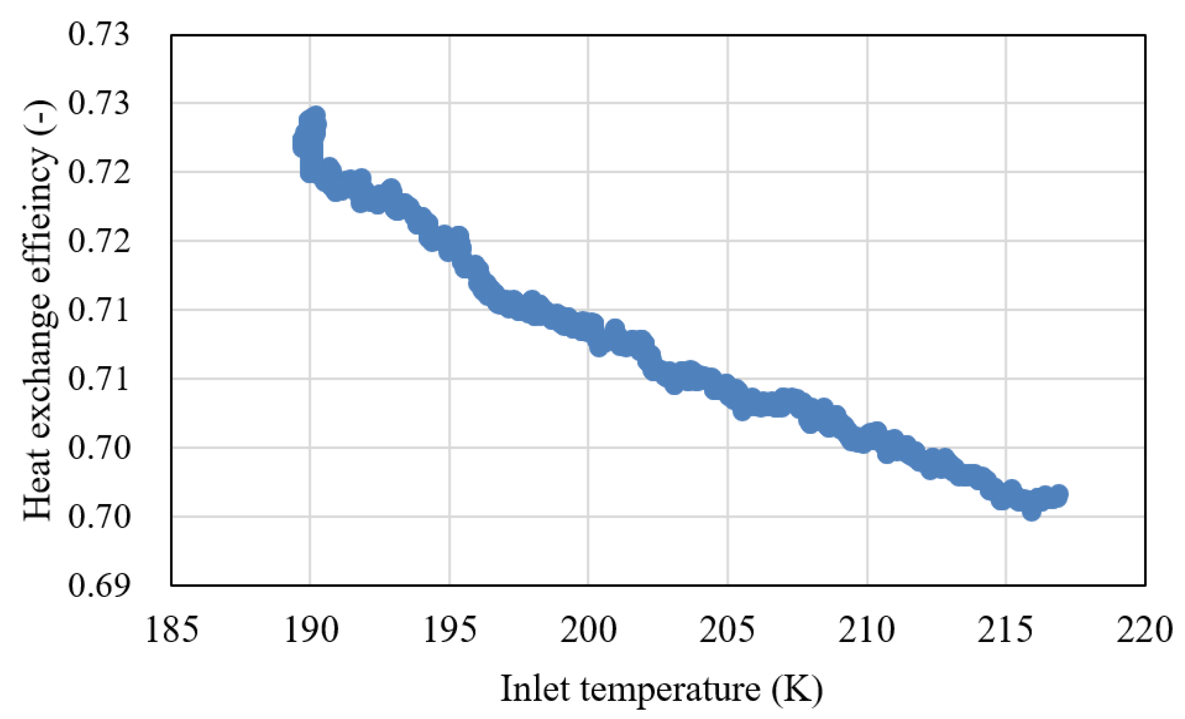
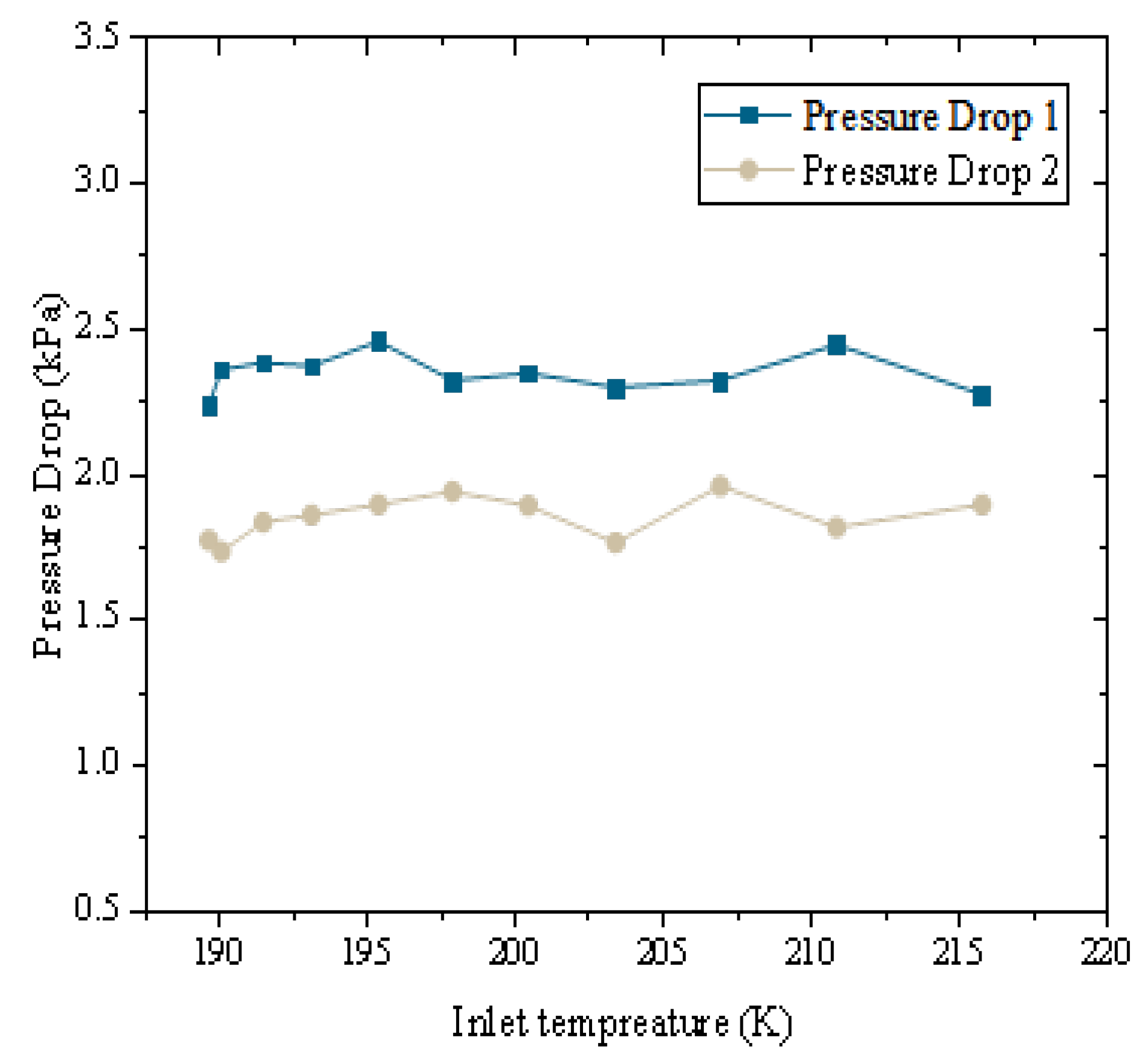
- The heat exchanger demonstrates exceptional heat-transfer efficiency and thermal retention capabilities. As the inlet temperature rises, so does the heat-transfer capacity. The heat-transfer discrepancy between the hot and cold fluids is minimal, with peak efficiency reaching 72%. The pressure drop remains stable across varying temperatures, with values of 2.5 kPa and 1.8 kPa for the cold and hot sides, respectively. These characteristics align well with the stringent demands of waste-heat recovery systems.
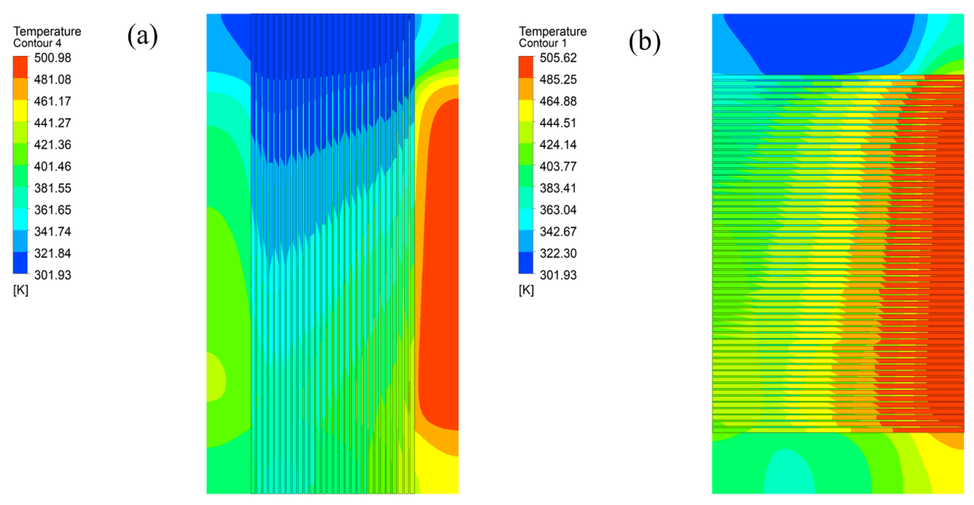
- Detailed profiles of temperature, pressure, and velocity distributions within the heat exchanger have been elucidated. Both fluids exhibit temperature gradients, though the hot fluid’s temperature distribution is notably more uniform. Pressure decreases progressively along the flow direction, with the cold fluid’s pressure drop being more temperature-sensitive compared to the hot fluid. The hot fluid’s velocity significantly outpaces that of the cold fluid. Additionally, the Nusselt number and convective heat-transfer coefficient for the hot fluid exceed those of the cold fluid, escalating in tandem with increases in the cold fluid’s inlet temperature and flow rate.
- With the utilization of a genetic algorithm, high-precision heat-transfer correlations for both the hot and cold sides were derived from the amalgamation of experimental and simulation data. These correlations boast a prediction accuracy within a 20% margin, thereby furnishing a robust theoretical framework to underpin associated design and application endeavors.
Author Contributions
Funding
Data Availability Statement
Conflicts of Interest
Nomenclature
| Abbreviations | |||
| CFD | Computational fluid dynamics | Q | Heat-transfer rate (kW) |
| PCHE | Printed-circuit heat exchanger | m | Mass flow rate (kg) |
| ORC | Organic Rankine cycle | V | Volume (m3) |
| w | Weight of the whole heat exchanger (kg) | ||
| Symbols | |||
| A | Heat-transfer area | Greek letters | |
| Cp | Specific heat (J/(kg·K)) | Density (kg/m3) | |
| D | Hydraulic diameter, (mm) | Dynamic viscosity (Pa·s) | |
| h | Convective heat-transfer coefficient | Turbulent kinetic energy dissipation rate | |
| Re | Reynolds number | ||
| Nu | Nusselt number | Subscripts | |
| k | Turbulent thermal conductivity | in | Inlet |
| p | Pressure (kPa) | out | Outlet |
| Pressure (kPa) | |||
References
- Narwal, K.; Kempers, R.; O’Brien, P.G. Enhanced energy storage density in thermal energy storage systems simultaneously heated with solar radiation and industrial waste heat. Results Eng. 2024, 25, 103792. [Google Scholar] [CrossRef]
- Du, K.; Calautit, J.; Eames, P.; Wu, Y. A state-of-the-art review of the application of phase change materials (PCM) in Mobilized-Thermal Energy Storage (M-TES) for recovering low-temperature industrial waste heat (IWH) for distributed heat supply. Renew. Energy 2021, 168, 1040–1057. [Google Scholar] [CrossRef]
- Wiśniewska, P.; Wang, S.; Formela, K. Waste tire rubber devulcanization technologies: State-of-the-art, limitations and future perspectives. Waste Manag. 2022, 150, 174–184. [Google Scholar] [CrossRef]
- Chen, T.; Shu, G.; Tian, H.; Zhao, T.; Zhang, H.; Zhang, Z. Performance evaluation of metal-foam baffle exhaust heat exchanger for waste heat recovery. Appl. Energy 2020, 266, 114875. [Google Scholar] [CrossRef]
- Deepak, G.; Sudha, L.; Pauline, S.; Ketaraju, V.D.S.; Aravindan, N.; Neelima, S. Thermodynamic modeling and AI-enhanced optimization of a novel tri-level waste heat recovery system for industrial processes. Therm. Sci. Eng. Prog. 2024, 56, 103098. [Google Scholar]
- Lykas, P.; Atsonios, K.; Gkountas, A.; Bakalis, P.; Manolakos, D.; Grammelis, P.; Itskos, G.; Nikolopoulos, N. Energy, exergy, and economic comparison of ORC with quasi-isothermal expansion with other ORC designs for low-grade waste heat recovery. Therm. Sci. Eng. Prog. 2024, 55, 103010. [Google Scholar] [CrossRef]
- Akbari, S.; Faghiri, S.; Zinjanabi, A.M.; Bijarchi, M.A.; Shafii, M.B.; Hosseinzadeh, K. Thermo-economic investigation and comparative multi-objective optimization of dual-pressure evaporation ORC using binary zeotropic mixtures as working fluids for geothermal energy application. Int. J. Thermofluids 2024, 24, 100899. [Google Scholar] [CrossRef]
- Bellos, E. A detailed analysis of waste heat recovery organic Rankine cycle with partial evaporation and different working fluids. Appl. Therm. Eng. 2025, 263, 125410. [Google Scholar] [CrossRef]
- Shalby, M.; Marachli, A.; Salah, A.A. Working Fluid Selection and Performance Analysis for Subcritical Organic Rankine Cycles. Results Eng. 2025, 25, 104120. [Google Scholar] [CrossRef]
- Ibrahim, O.A.A.-M.; Kadhim, S.A.; Hammoodi, K.A.; Rashid, F.L.; Askar, A.H. Review of hydrocarbon refrigerants as drop-in alternatives to high-GWP refrigerants in VCR systems: The case of R290. Clean. Eng. Technol. 2024, 23, 100825. [Google Scholar] [CrossRef]
- Kittijungjit, T.; Klamrassamee, T.; Laoonual, Y.; Sukjai, Y. Comprehensive study on waste heat recovery from gas turbine exhaust using combined steam Rankine and organic Rankine cycles. Energy Convers. Manag. 2025, 25, 100825. [Google Scholar] [CrossRef]
- Wang, J.; Tian, H.; Sun, R.; Wang, X.; Li, L.; Zhang, X.; Shu, G. Computer-aided molecular design of CO2-based mixture working fluid harvesting engine waste heat. Appl. Therm. Eng. 2023, 227, 120481. [Google Scholar] [CrossRef]
- Feng, X.; Shi, F.; Qiao, G.; Li, Y.; Liu, C. Integrating organic Rankine cycle with thermoelectric generator in various applications utilizing low-grade energy: A review. Sustain. Energy Technol. Assess. 2024, 68, 103882. [Google Scholar] [CrossRef]
- Chowdhury, A.S.; Ehsan, M.M. A Critical Overview of Working Fluids in Organic Rankine, Supercritical Rankine, and Supercritical Brayton Cycles Under Various Heat Grade Sources. Int. J. Thermofluids 2023, 20, 100426. [Google Scholar] [CrossRef]
- Lee, S.W.; Lee, Y.; Lee, Y.; Jo, H. Condensation heat transfer and applicability assessment of a printed circuit heat exchanger as a condenser in a cryogenic CO2 capture and storage system. Appl. Therm. Eng. 2024, 261, 125133. [Google Scholar] [CrossRef]
- Xia, E.; Xie, H.; Sun, L.; Long, X.; Wang, J.; Gao, T.; Li, S.; Li, B.; Li, C.; Gao, M.; et al. Optimal design of a high-performance heat exchanger for modular thermoelectric generator towards low-grade thermal energy recovery. Appl. Therm. Eng. 2024, 258, 124849. [Google Scholar] [CrossRef]
- Zhang, L.; Yang, P.; Li, W.; Klemeš, J.J.; Zeng, M.; Wang, Q. A new structure of PCHE with embedded PCM for attenuating temperature fluctuations and its performance analysis. Energy 2022, 254, 124462. [Google Scholar] [CrossRef]
- Tang, Z.; He, S.; Li, N.; Zeng, M.; Yan, X.; Wang, Q.; Ma, T. Non-equilibrium overlapping grid method with two-phase porous media model for printed circuit heat exchanger based steam generator. Int. J. Heat Mass Transf. 2024, 232, 125960. [Google Scholar] [CrossRef]
- Chen, W.; Ma, Q.; Liu, X.; Cheng, Y.; Wang, Q.; Ma, T. Adaptability analysis of flow and heat transfer multi-scale numerical method for printed circuit heat exchanger. Energy 2024, 311, 133349. [Google Scholar] [CrossRef]
- Liang, Z.; Zheng, G.; Wu, G.; Pan, Z.; Hu, Z.; Xu, M.; Chen, H. Thermodynamic performance of organic rankine cycle based pumped thermal energy storage system with different working fluids. Heliyon 2024, 11, e41052. [Google Scholar] [CrossRef]
- Kim, I.H.; Sun, X. CFD study and PCHE design for secondary heat exchangers with FLiNaK-Helium for SmAHTR. Nucl. Eng. Des. 2014, 270, 325–333. [Google Scholar] [CrossRef]
- Mondejar, M.E.; Andreasen, J.G.; Pierobon, L.; Larsen, U.; Thern, M.; Haglind, F. A review of the use of organic Rankine cycle power systems for maritime applications. Renew. Sustain. Energy Rev. 2018, 91, 126–151. [Google Scholar] [CrossRef]
- Ren, Y.; Jiang, R.; Wang, P.; Wu, W.; Yang, Y.; Yang, Q. Experimental study of a rectangular microchannel printed circuit heat exchanger using supercritical carbon dioxide and water cooling. Appl. Therm. Eng. 2024, 262, 125230. [Google Scholar] [CrossRef]
- Ali, S.; Nohra, C.; Faraj, J.; Dbouk, T.; Khaled, M. Thermo-hydraulic performance of concentric tube heat exchangers with turbulent flow: Predictive correlations and iterative methods for pumping power and heat transfer. Int. J. Thermofluids 2024, 24, 100898. [Google Scholar] [CrossRef]
- Yih, J.; Wang, H. Experimental characterization of thermal-hydraulic performance of a microchannel heat exchanger for waste heat recovery. Energy Convers. Manag. 2020, 204, 112309. [Google Scholar] [CrossRef]
- Zhu, H.; Xie, G.; Berrouk, A.S. Comparative dynamic performance of SCO2 cycle and combined cycle with transiently modelled printed circuit heat exchangers. Appl. Therm. Eng. 2024, 257, 124342. [Google Scholar] [CrossRef]
- Zhang, H.; Shi, L.; Xuan, W.; Chen, T.; Li, Y.; Tian, H.; Shu, G. Analysis of printed circuit heat exchanger (PCHE) potential in exhaust waste heat recovery. Appl. Therm. Eng. 2022, 204, 117863. [Google Scholar] [CrossRef]
- Kazaz, O.; Abu-Nada, E. Innovative high-energy nanocomposite absorbers for superior solar-driven water desalination through broadband solar energy harvesting. Appl. Therm. Eng. 2025, 273, 126531. [Google Scholar] [CrossRef]
- Ravi, R.; Pachamuthu, S.; Kasinathan, P. Computational and experimental investigation on effective utilization of waste heat from diesel engine exhaust using a fin protracted heat exchanger. Energy 2020, 200, 117489. [Google Scholar] [CrossRef]
- Baigh, T.A.; Saif, M.J.; Mustakim, A.; Nanzeeba, F.; Khan, Y.; Ehsan, M.M. Enhancing thermodynamic performance with an advanced combined power and refrigeration cycle with dual LNG cold energy utilization. Heliyon 2024, 10, e35748. [Google Scholar] [CrossRef]
- Huang, Y.; Sarma, B.; Weibel, J.A. A predictive model for fin array boiling heat transfer performance under two-phase immersion cooling. Int. J. Heat Mass Transf. 2025, 239, 126513. [Google Scholar] [CrossRef]


| Parameter [Unit] | Values |
|---|---|
| Length of core size [mm] | 160 |
| Width of core size [mm] | 90 |
| Height of core size [mm] | 130 |
| Heat-transfer area (hot side) [m2] | 0.64 |
| Heat-transfer area (cold side) [m2] | 0.52 |
| Number of channel holes (hot side) [-] | 57 |
| Number of channel holes (cold side) [-] | 28 |
| Number of plates (hot side) [-] | 40 |
| Number of plates (cold side) [-] | 40 |
| Number of weight [kg] | 20 |
| Case | Hot Side (Cyclopen) | Cold Side (Cyclopen) | ||||
|---|---|---|---|---|---|---|
| (kg/s) | (K) | (kPa) | (kg/s) | (K) | (kPa) | |
| Case1 | 0.13 | 453 | 105 | 0.13 | 325 | 2100 |
| Case | Hot Side (Cyclopen) | Hot Side (Cyclopen) | ||||||
|---|---|---|---|---|---|---|---|---|
| (kg/s) | (K) | (kPa) | (kg/s) | (K) | (K) | (kPa) | ||
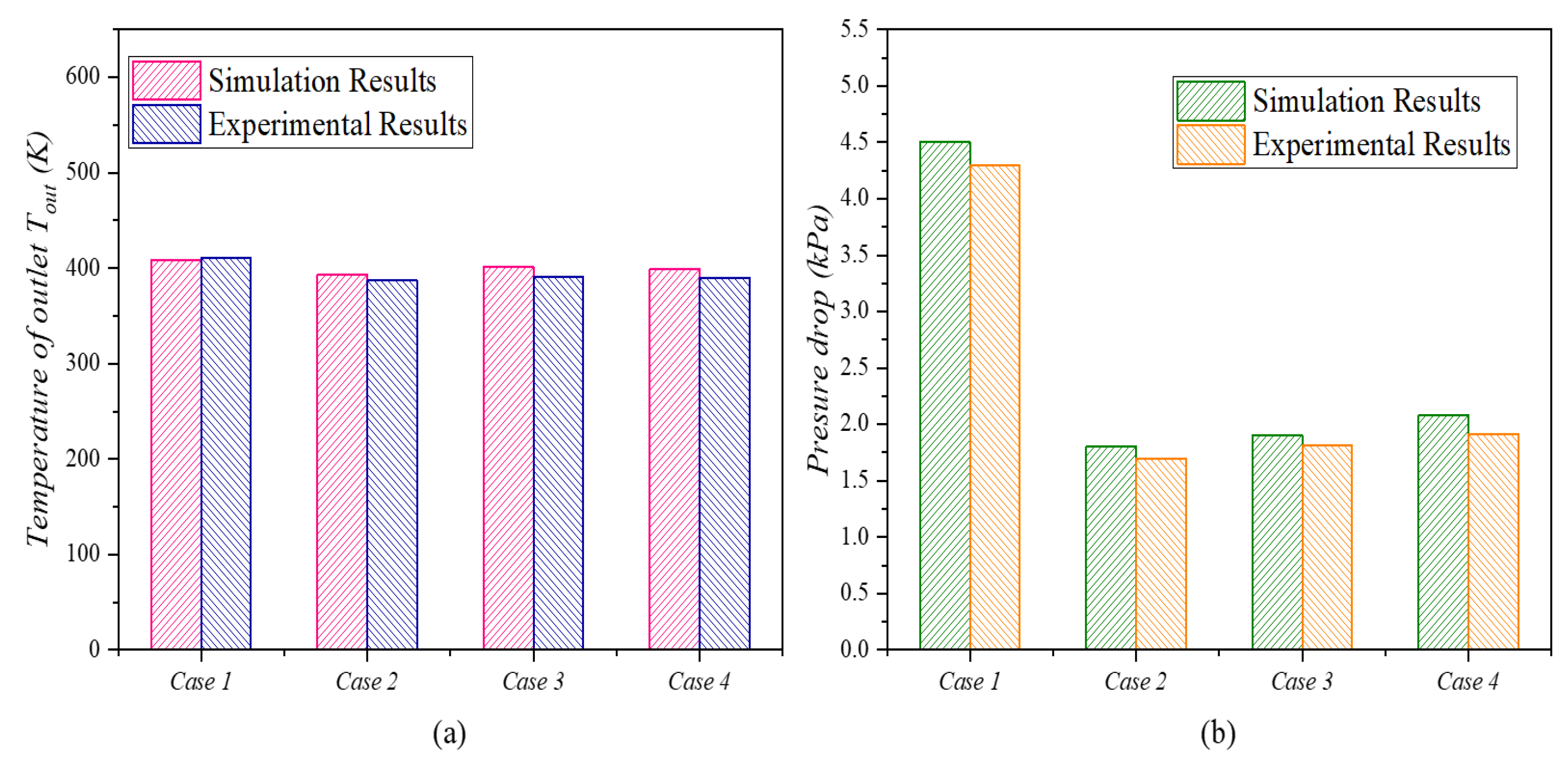
| Case1 | 0.13 | 453 | 411 | 5 | 0.13 | 325 | 362 | 4 |
| Simulation Results | 0.13 | 453 | 408 | 4.3 | 0.13 | 325 | 365 | 3.9 |
Disclaimer/Publisher’s Note: The statements, opinions and data contained in all publications are solely those of the individual author(s) and contributor(s) and not of MDPI and/or the editor(s). MDPI and/or the editor(s) disclaim responsibility for any injury to people or property resulting from any ideas, methods, instructions or products referred to in the content. |
© 2025 by the authors. Licensee MDPI, Basel, Switzerland. This article is an open access article distributed under the terms and conditions of the Creative Commons Attribution (CC BY) license (https://creativecommons.org/licenses/by/4.0/).
Share and Cite
Qin, X.; Xu, H.; Zhang, H.; Zhang, M.; Sun, L.; Wang, X. Experimental and Simulation-Based Development of Heat-Transfer Correlations for Cyclopentane PCHE. Energies 2025, 18, 2744. https://doi.org/10.3390/en18112744
Qin X, Xu H, Zhang H, Zhang M, Sun L, Wang X. Experimental and Simulation-Based Development of Heat-Transfer Correlations for Cyclopentane PCHE. Energies. 2025; 18(11):2744. https://doi.org/10.3390/en18112744
Chicago/Turabian StyleQin, Xiaogang, Haibo Xu, Hongfei Zhang, Ming Zhang, Lin Sun, and Xuan Wang. 2025. "Experimental and Simulation-Based Development of Heat-Transfer Correlations for Cyclopentane PCHE" Energies 18, no. 11: 2744. https://doi.org/10.3390/en18112744
APA StyleQin, X., Xu, H., Zhang, H., Zhang, M., Sun, L., & Wang, X. (2025). Experimental and Simulation-Based Development of Heat-Transfer Correlations for Cyclopentane PCHE. Energies, 18(11), 2744. https://doi.org/10.3390/en18112744