Abstract
In order to reduce the emissions caused by internal combustion engine vehicles, the industry is introducing more and more electric or hybrid vehicles to the market nowadays. The battery cells and modules of these vehicles require a lot of care, as improper or improperly maintained battery units can cause serious problems inside vehicles and can be extremely dangerous. The safest solution is to keep this unit of a vehicle under constant supervision so that it can be repaired immediately in case of an issue. Since all necessary data can be extracted from a vehicle’s communication network(s) through standard communication protocols, it is advisable to use them for continuous monitoring and diagnostics of units, while also considering cost-effectiveness and simplicity. The data received from here can also be used for measurement of electric powertrains and other parameters. However, since these data go through many conversions and computers (ECUs) before reaching us, their accuracy is questionable. In this study, we present our own custom battery diagnostic tool based on data extracted from a communication network. With the help of commercially available diagnostic tools, we also compare several measurements of the extent of the error limits of the data arriving at the communication network, how far they differ from the real values, and with the help of these, we analyze the accuracy of the device we have made. We present the commonly used Controller Area Network (CAN) communication protocol for passenger vehicles and briefly describe the construction of the high-voltage battery unit of the test vehicle.
1. Introduction
To reduce the emission of harmful substances, there are now more and more electric or hybrid vehicles on the roads. In these vehicles, the energy required to drive the electric motor is provided in the form of electricity stored in high-voltage battery modules. A whole battery pack consists of several cells that are highly flammable if their condition is no longer adequate, so it is advisable to constantly monitor them. The aim of our research is to develop a cost-effective battery diagnostic tool that utilizes a contactless connection to the vehicle’s communication network for data collection. This tool avoids disassembly of the vehicle, enables real-time monitoring, and provides the capability of recording data for subsequent analysis. In vehicles manufactured since the 2000s, communication networks are increasingly common. Due to the development of technology and the increased amount of data, it is essential that car manufacturers use some kind of protocol. Currently, the most used communication network is the CAN (Controller Area Network), as it is a cost-effective and simple solution in the automotive industry. Almost all of a vehicle’s data can be extracted and used for various tests, including for diagnostic purposes. Since these data always go through analog-to-digital conversion and pass through several sensors and ECUs, the question arises as to how accurate they are compared to the real values. An accurate set of data is essential for vehicle industry measurements and reliable statements, so we examined how far the data coming from the mentioned network deviate from the real values, and whether the battery we developed can be used for diagnostic purposes.
One of the major disadvantages of commercially available vehicle diagnostic tools suitable for the purpose is that our options are limited. We cannot monitor more than eight pieces of data at a time, and we do not have the option of saving the data for later evaluations. During the development of the device we created, we tried to make up for these shortcomings and to add features that we considered important from a battery diagnostic point of view.
The test was performed on the high-voltage battery system of a Gen3 Toyota Prius Hybrid vehicle. The comparison of the data and the validation of our own device were conducted with diagnostic test devices from two different manufacturers, as well as with a certified multimeter suitable for measuring high voltages.
Literature Review
Most passenger vehicles use the fairly common communication network the Controller Area Network (CAN) for its cost-effectiveness and simplicity. Following the current standards, many diagnostic tools also communicate via the CAN network, via OBD-II or EOBD connectors. The information necessary to understand this topic is explained in detail in this chapter [1,2].
Increasingly complex vehicle systems, especially for electric and hybrid models, require advanced diagnostic tools for safety and efficiency. Modern communication protocols, such as the CAN FD (Controller Area Network Flexible Data-Rate) and Time-Sensitive Networking (TSN), improve data transfer rates and communication accuracy, supporting key vehicle functions such as automated driving and battery health monitoring [3]. However, vehicle networks also present security gaps, such as [4], where attackers can penetrate critical systems such as brakes and engine control.
Accurate estimation of state of charge (SOC) and state of health (SOH) is essential for electric vehicles. The author in [5] highlighted the importance of real-time SOH data in detecting battery problems, while in [6], the authors investigated sophisticated models for SOC estimation that optimize battery performance in hybrid electric vehicles. Cold weather poses additional challenges to lithium-ion batteries, affecting performance and safety, so accurate monitoring is vital [7].
On-board diagnostic (OBD) systems are constantly evolving, with OBD-II offering standardized data for diagnosing a variety of vehicles. The forthcoming OBD-III system will incorporate wireless communication for immediate troubleshooting [8,9]. In addition, a system was developed that utilizes CAN bus data and smartphones for real-time battery diagnostics of hybrid vehicles, showcasing the potential for cost-effective remote monitoring.
Artificial intelligence (AI) techniques such as neural networks and fuzzy logic, as noted by the authors of [10], enhance vehicle health management by identifying anomalies and predicting system failures. Predictive maintenance methods, as outlined in [11], also enable continuous tracking of vehicle components to minimize unexpected failures and improve overall efficiency, which is particularly beneficial for EV batteries. Techniques like curvilinear Manhattan distance evaluation and voltage difference analysis also contribute to multi-fault diagnosis by providing a more detailed layer of analysis, offering the potential to improve fault detection accuracy and efficiency in battery diagnostics.
In the past, automakers used point-to-point wire networks to connect electrical devices in vehicles. However, more and more electronics began to be used in modern cars, which resulted in bulky and expensive wire harnesses. Therefore, these systems were replaced by vehicular networks, which reduced the cost, complexity, and weight of the wiring [2,12,13,14,15]. The most common such communication network is the CAN, which is widely used due to the following advantages:
- Fewer wires required (reducing the possibility of errors resulting from incorrect connections, and reducing weight and cost)
- The value of the sensors can be used for several control units (ECUs) without using a separate wire
- Enables high-speed communication (1 Mbit/s)
- Due to the size of the controllers and cable harnesses, more space remains for other purposes
- To expand communication data capacity, it is sufficient to modify the software (program)
- Due to continuous monitoring on the network, the error rate is minimal
- Complies with international guidelines (recorded in the ISO 11898 standard) [1,12,15,16,17,18,19,20]
The CAN communication system used in vehicles is a two-wire bus to which the controllers (ECUs) are connected in parallel. The standard cable is a twisted pair, available in both shielded and unshielded designs. Since the CAN operates exclusively with digital signals, the controller connects to the bus through a transceiver circuit, which performs the necessary voltage-level conversion from the UART bus to the CAN bus (Figure 1). Another important task of the controller is to prevent data collisions on the bus through a process known as arbitration [15,21,22,23].
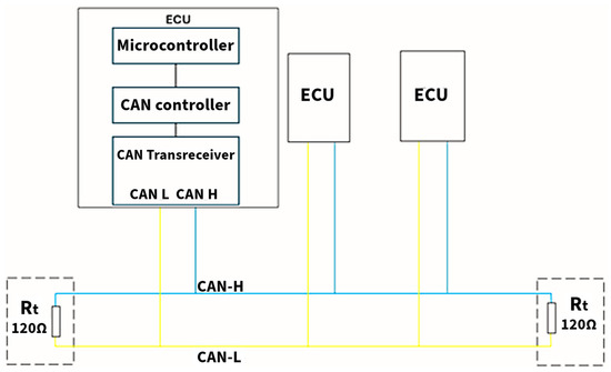
Figure 1.
Physical structure of the CAN bus.
Since the CAN network works with low voltage values, voltage waves reflected from the end of the wire can interfere with normal operations and result in incorrect data. This is called reflection, and to eliminate reflection, manufacturers use terminating resistors at the end of the wires (Figure 1), the value of which is 120 Ω [12,14].
The maximum speed of CAN systems is 1 Mbit/s, which can be achieved on a cable of up to 40 m in length. If a bus network longer than this would be necessary from the design point of view, we must consider a reduction in bit rate. Using the CAN bus, a distance of 1000 m can be bridged, but then the bit rate drops to 50 kbit/s. The figure below (Figure 2) shows the bit rates for each distance [14,18].
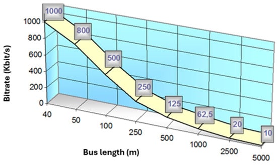
Figure 2.
Bit rate and bus length ratio [14].
As is customary with serial data transmission, the message is packed within a frame format. The message frame is subdivided into additional fields, which are populated with bits (Figure 3). Table 1 summarizes the meaning of the abbreviations in each field. The bit sequences filling the message frame perform different tasks, such as data transmission or error detection. In the case of CAN messages, two types are distinguished (Figure 3): the standard message frame, whose identification field consists of 11 bits, and the extended message frame, whose identification field consists of 29 bits. This bit extension enables 536,870,912 variations of identifiers (ID) instead of 2048 [12,14,19,21].
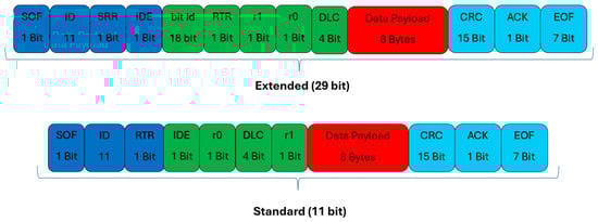
Figure 3.
Structure of a CAN message frame.

Table 1.
Meaning of data frame abbreviations.
The right to use the bus is decided by the so-called arbitration process, and within it the arbitration field. In the case of a standard message frame, 11 + 1 bits (ID + RTR), and in the case of an extended frame, 11 + 2 + 18 + 1 bits (ID + SRR + IDE + bit ID + RTR). The values of the arbitration field decide on access to the bus: the lower the numerical value of the identifier (i.e., the more dominant (0) rather than recessive (1) values) the higher its priority on the bus [1,16,22].
The message with the highest priority starts sending to the bus (Figure 4). The other nodes can then start sending the message when the bus is free. The bus can be considered free if the pause following the messages was not interrupted by a dominant (i.e., 0) bit. This means that 11 recessive bits must arrive at the end of a message (ACK Delimiter 1 bit + EOF 7 bits + Intermission 3 bits = 11 bits) [12,13,21].
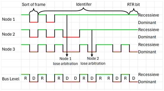
Figure 4.
The process of deciding the right to use a bus.
2. Materials and Methods
It can be read in the introduction that these CAN data go through an analog-to-digital conversion. To make sure of their accuracy, we also checked the real value of the battery with another measuring device.
The examined data were the following:
- Module voltage (a total of 14 modules, consisting of 28 cells): in this case, we did not examine the cell voltages, since no cell voltage data are received on the vehicle’s CAN network, so this is also possible for comparison with the diagnostic devices.
- Hybrid battery voltage.
The module voltages and battery voltage were first measured in a stationary position without any load, and then re-measured with the load activated. The consumer in this case was the air conditioner, as this is the one unit in the vehicle that operates at a high voltage and can be operated in a stationary position. As mentioned above, the diagnostic tools also communicate via the CAN with the vehicle’s controllers via a standard OBD-II connector. Since these diagnostic tools are approved by the vehicle manufacturers, they have provided us with a good reference for comparison. The measurements were first performed with two different diagnostic devices and then with our own device (Figure 5).
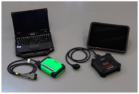
Figure 5.
Diagnostic tools used for measurement.
In operation, the two diagnostics devices (later diagnostics1 and diagnostics2) do not differ much from each other. Both devices send “request codes” (approved by the manufacturer) to an ECU of the vehicle and the vehicle responds with a code according to the request code. In our case, this response message is a CAN message frame, which the devices convert into a value we can understand after decoding (e.g., V, A, km/h, etc.). There may be a difference in the conversion depending on the factor (i.e., the multiplier) used by the manufacturer during decoding, or how many decimal places the received value is rounded to.
A major drawback of both diagnostic tools is that we cannot monitor more than eight data points simultaneously, and the data can only be recorded as a screen capture, which complicates later data processing. During the investigation, we wanted to monitor a total of 16 data points at the same time and save the data for later processing. Since none of these options were possible with these devices, we put together a unique measuring system that is capable of achieving the goals we set.
Presentation of Own Diagnostic Tool
Based on what was described above, it can be seen that our possibilities with diagnostic tools are very limited both in terms of monitoring the number of data points and recording them. Our goal was to be able to monitor and record all the battery data that we consider important at the same time.
Since the device was not made for industrial purposes, but exclusively for research purposes, longevity was not a significant parameter. For this reason, the hardware part was developed on a low budget, using an Arduino-type development board. For the implementation, two Arduinos were needed, because based on the previous tests, one Arduino could not fulfill the sending and receiving role, resulting in data loss.
To avoid this, we used one sending and one receiving unit. Since the Arduino itself is not capable of processing CAN data, we had to use an additional MCP2515 chip in both cases. We used the autowp-mcp25 library for the operation of the MCP2515 controller. A separate terminating resistor was not integrated into the system, as the vehicle’s CAN bus backbone network already has terminating resistors. In terms of functionality, the device does not differ from diagnostic tools. With the sending unit, we post a request code also sent by diagnostics to the vehicle’s network, and the vehicle responds with a CAN message. We receive this response message from the receiving unit and then decode it using the decoding file we created, so we obtain the desired values. The flowchart below illustrates the operation of our device (Figure 6).
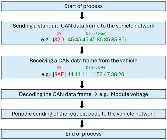
Figure 6.
The process of operation of the diagnostic tool we developed.
The diagram below (Figure 7) illustrates the assembled system, with its connection points summarized in Table 2. Since the Arduino itself can operate independently after uploading the appropriate code, the sending unit sends the request code to the vehicle at appropriate intervals without interruption, and with the receiving unit, we can monitor the selected values in a separate window on the computer via a USB cable.
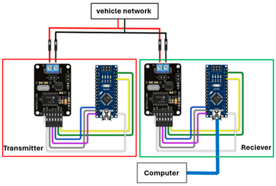
Figure 7.
Construction and connection of our device.
Table 2.
Connection Arduino and MCP2515.
We designed the battery diagnostic interface in such a way that we can observe the data that we consider important from a battery diagnostic point of view. As shown in the figure (Figure 8), unlike the vehicle diagnostic tools, we have the opportunity to observe much more than 8 data points in real time, and we were also able to record them, which the program saves in .txt format.
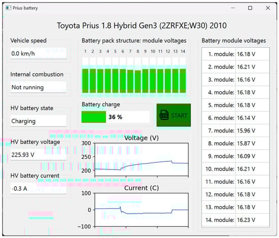
Figure 8.
Battery monitoring system interface created by us.
Our software was developed in Python, (Python 3.12.5) and we used the PyQt6 package to design the user interface. Serial communication was implemented between the desktop application and the Arduino, with a baud rate of 500,000. The desktop receives CAN messages from the Arduino, decodes them, and displays them to the user.
3. Results
In the third-generation Prius that we examined, there is a nickel–metal hydride (NiMH) battery unit with a nominal voltage of 201.6 V. This unit comprises 28 low-voltage cells, each rated at 7.2 V, connected in series to form 14 modules, with each module having a nominal voltage of 14.4 V [24,25,26].
The designated measurement points are shown in the diagram below (Figure 9), which were established to verify the data.
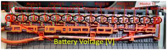
Figure 9.
Battery unit measurement points.
Since we do not have the possibility of recording live data within diagnostic software (only in image format), the measured values of the modules and the battery unit have been summarized in a table for easier overview, without consumers (unloaded condition) and with the air conditioner switched on (loaded condition). During the investigation, we did not check the accuracy of the data and the authenticity of the device we made in three measurement series. In the first measurement series, we examined the data using diagnostics1, and in the second measurement series, diagnostics2, and then validated the values of the device we created. Finally, we also examined our own device in the third measurement series. Identical values are marked in green, and those that are different in red. We performed 10 measurements in each measurement series, the results of only one selected measurement are shown in the tables below. The real values of the battery were tested in parallel with a certified Fluke-type multimeter suitable for measuring high voltages.
Table 3, Table 4 and Table 5 clearly show that there are considerable discrepancies between the data received via the CAN and the measured data. By calculating the differences, it can be observed that the differences range from 0.01 to 0.17. The values of the standard deviations can be seen in the Figure 10, Figure 11 and Figure 12 for a better illustration.
Table 3.
The results of the first series of measurements.
Table 4.
The results of the second series of measurements.
Table 5.
The results of the third series of measurements.
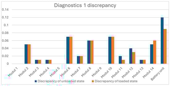
Figure 10.
Diagnostics 1 discrepancy.
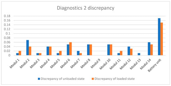
Figure 11.
Diagnostics 2 discrepancy.
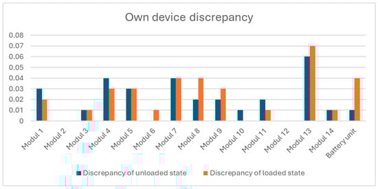
Figure 12.
Own device discrepancy.
In this case, we can observe the complete identity for three modules and the maximum difference for the other modules is 0.07 hundredths. The largest dispersion can be observed in the value of the battery unit, the maximum value of which is 0.12 hundredths.
In the case of the second method, we find a match for only one module, but the values of the dispersion are smaller for the other units. The maximum spread of the blocks is 0.07 hundredths. The highest dispersion value can also be observed here in the case of the battery pack with a maximum value of 0.17 hundredths.
In the case of the device we have made, scatters can also be observed, the largest value of which is 0.07 hundredths. This was to be expected, since we used the diagnostic tools to decrypt the data. Unlike the diagnostic tools, the value of the battery pack was determined by the sum of the module voltages. With this method, we were able to significantly reduce the dispersion, achieving a more accurate value than with the diagnostic tools. Regarding the diagnostic tools, the big difference observed in the case of the battery pack is probably due to the rounding inaccuracy, because, as can be seen in the tables, this value is available rounded to the whole.
4. Conclusions
In this article, our only developed battery monitoring method was presented, as well as a comparison of the data received via the CAN and the data measured for real. From the results of our measurements, it can be concluded that the actual values and the data received on the CAN bus do not always match. However, these differences can be said to be minimal in terms of module voltages, with the largest difference being seven-hundredths. In the battery pack voltage test, the discrepancies were much larger regarding the diagnostic tools, which presumably resulted from rounding problems. With the tool we created, we managed to solve this rounding inaccuracy from the sum of the module voltages, so we managed to reduce the difference between the data to a difference of one–four-hundredths. Even though factory diagnostic tools are capable of monitoring real values, our solution can be said to be better because we tried to correct the shortcomings of these tools. The number of data points that can be observed is not limited, and it is also possible to record the data in “txt” format. The measured deviations in the measurements and tests we carry out are well within tolerance, we do not need more precise values. Based on the above, it can be seen that a battery monitoring system can be implemented easily and cost-effectively.
There is no need to install additional tools, as the vehicle’s own communication network can be used to extract these data. Furthermore, there is no need for significant disassembly of the vehicle. On the other hand, if we want a complete and exact match, the data coming via CAN is not suitable, in which case a different method must be used for the test.
Author Contributions
Conceptualization, B.B.; methodology, B.B. and G.S.; software, B.B. and G.S.; validation, L.P.; technology outlook, writing—review and editing, B.B. and G.S.; data evaluation, B.B., G.S. and L.P.; writing, B.B.; visualization, B.B. and G.S. All authors have read and agreed to the published version of the manuscript.
Funding
This research and the APC were funded by Széchenyi István University.
Data Availability Statement
The original contributions presented in the study are included in the article, further inquiries can be directed to the corresponding author.
Conflicts of Interest
The authors declare no conflicts of interest.
References
- Smith, G.M. What Is CAN Bus (Controller Area Network) and How It Compares to Other Vehicle Bus Networks; Dewesoft: Trbovlje, Slovenia, 2024; Available online: https://dewesoft.com/blog/what-is-can-bus (accessed on 12 July 2024).
- Han, K.; Mun, H.; Balakrishnan, M.; Yeun, C.Y. Enhancing security and robustness of Cyphal on Controller Area Network in unmanned aerial vehicle environments. Comput. Secur. 2023, 135, 103481. [Google Scholar] [CrossRef]
- Zhu, H.; Zhou, W.; Li, Z.; Li, L.; Huang, T. Requirements-driven automotive electrical/electronic architecture: A survey and prospective trends. IEEE Access 2021, 9, 100096–100112. [Google Scholar] [CrossRef]
- Koscher, K.; Czeskis, A.; Roesner, F.; Patel, S.; Kohno, T.; Checkoway, S.; McCoy, D.; Kantor, B.; Anderson, D.; Shacham, H.; et al. Experimental security analysis of a modern automobile. In Proceedings of the 2010 IEEE Symposium on Security and Privacy, Oakland, CA, USA, 16–19 May 2010; pp. 447–462. [Google Scholar] [CrossRef]
- Noura, N.; Boulon, L.; Jemeï, S. A review of battery state of health estimation methods: Hybrid electric vehicle challenges. World Electr. Veh. J. 2020, 11, 66. [Google Scholar] [CrossRef]
- Tudoroiu, R.-E.; Zaheeruddin, M.; Tudoroiu, N.; Radu, S.-M. SOC estimation of a rechargeable Li-ion battery used in fuel-cell hybrid electric vehicles—Comparative study of accuracy and robustness performance based on statistical criteria. Batteries 2020, 6, 42. [Google Scholar] [CrossRef]
- Jaguemont, J.; Boulon, L.; Dubé, Y. A comprehensive review of lithium-ion batteries used in hybrid and electric vehicles at cold temperatures. Appl. Energy 2016, 164, 99–114. [Google Scholar] [CrossRef]
- Singh, S.K.; Singh, A.K. A Study: OBD III Standard and Its Predecessors OBD II and OBD I; Mody University: Rajasthan, India, 2020. [Google Scholar]
- Yang, Y.; Chen, B.; Su, L.; Qin, D. Research and Development of Hybrid Electric Vehicles CAN-Bus Data Monitor and Diagnostic System through OBD-II and Android-Based Smartphones. Adv. Mech. Eng. 2013, 2013, 319526. [Google Scholar] [CrossRef]
- Roemer, M.J.; Byington, C.S.; Schoeller, M.S. Selected artificial intelligence methods applied within an integrated vehicle health management system. In Proceedings of the IEEE Aerospace Conference Proceedings 2000, Big Sky, MT, USA, 25 March 2000; pp. 1–10. Available online: https://cdn.aaai.org/Symposia/Fall/2007/FS-07-02/FS07-02-013.pdf (accessed on 12 July 2024).
- Arena, F.; Collotta, M.; Luca, L.; Ruggieri, M.; Termine, F.G. Predictive maintenance in the automotive sector: A literature review. Math. Comput. Appl. 2022, 27, 2. [Google Scholar] [CrossRef]
- Balázs, S.; Tóth, C. Autóipari Kommunikációs Hálózatok Vizsgálata Laboratóriumi Mérések a Beágyazott és Ambiens Rendszerek Laboratórium Tárgyhoz V5h. Bosch-Beágyazott Rendszerek Laboratórium. 2008. Available online: https://docplayer.hu/46143120-Autoipari-beagyazott-rendszerek-can-controller-area-network.html (accessed on 13 August 2024).
- Fazekas, I. Járműipari Hálózatok. 2016. Available online: https://www.kjit.bme.hu/images/Tantargyak/Jarmumechatronika_szakirany/Jarmufedelzeti_rendszerek_II/jrmipari_hlzatok.pdf (accessed on 15 August 2024).
- Szalay, Z.; Fodor, D. Autóipari Kommunikációs Rendszerek. 2014. Available online: https://dtk.tankonyvtar.hu/bitstream/handle/123456789/3418/2011-0042_autoipari_kommunikacios_rendszerek.pdf?sequence=1&isAllowed=y (accessed on 19 August 2024).
- Qin, H.; Yan, M.; Ji, H. Application of Controller Area Network (CAN) bus anomaly detection based on time series prediction. Veh. Commun. 2021, 27, 100291. [Google Scholar] [CrossRef]
- Bokor, J.; Gáspár, P. Járműfedélzeti Kommunikáció. 2012. Available online: https://oszkdk.oszk.hu/storage/00/00/59/50/dd/1/Bokor_Gaspar_Jarmufedelzeti_kommunikacio.pdf (accessed on 22 August 2024).
- Tariq, S.; Lee, S.; Kim, H.K.; Woo, S.S. CAN-ADF: The controller area network attack detection framework. Comput. Secur. 2020, 94, 101857. [Google Scholar] [CrossRef]
- Navet, N.; Simonot-Lion, F. In-vehicle communication networks: A historical perspective and review. Ind. Commun. Technol. Handb. 2015, 96, 1204–1223. [Google Scholar]
- Ishak, M.K.; Khan, F.K. Unique message authentication security approach based on Controller Area Network (CAN) for anti-lock braking system (ABS) in vehicle network. In Procedia Computer Science; Elsevier: Amsterdam, The Netherlands, 2019; pp. 93–100. [Google Scholar] [CrossRef]
- ISO 11898:2015; Road Vehicles—Controller Area Network (CAN)—Part 1: Data Link Layer and Physical Signalling. International Organization for Standardization: Geneva, Switzerland, 2015.
- National Instruments. Controller Area Network (CAN) Overview. July 2024. Available online: https://www.ni.com/en/shop/seamlessly-connect-to-third-party-devices-and-supervisory-system/controller-area-network--can--overview.html (accessed on 23 August 2024).
- Shepard, J. What Is the Controller Area Network (CAN) Bus? Microcontroller Tips. 22 June 2022. Available online: https://www.microcontrollertips.com/what-is-the-controller-area-network-can-bus-faq/ (accessed on 23 August 2024).
- Zhao, Z.A.; Sun, Y.; Li, D.; Cui, J.; Guan, Z.; Liu, J. A scalable security protocol for intravehicular Controller Area Network. Secur. Commun. Netw. 2021, 2021, 2314520. [Google Scholar] [CrossRef]
- Toyota Motor Corporation. Hybrid 2010 Model 3rd Generation. 2009. Available online: http://techinfo.toyota.com (accessed on 2 September 2024).
- Hill, J. Diagnosing Prius Hybrid Battery Pack: Sometimes They Come Back. Toyotatech. 2022. Available online: https://automotivetechinfo.com/2022/05/diagnosing-prius-hybrid-battery-pack-sometimes-they-come-back/ (accessed on 2 September 2024).
- Kelly, K.J.; Mihalic, M.; Zolot, M. Battery Usage and Thermal Performance of the Toyota Prius and Honda Insight for Various Chassis Dynamometer Test Procedures: Preprint. National Renewable Energy Laboratory. 2002. Available online: http://www.osti.gov/bridge (accessed on 2 September 2024).
Disclaimer/Publisher’s Note: The statements, opinions and data contained in all publications are solely those of the individual author(s) and contributor(s) and not of MDPI and/or the editor(s). MDPI and/or the editor(s) disclaim responsibility for any injury to people or property resulting from any ideas, methods, instructions or products referred to in the content. |
© 2024 by the authors. Licensee MDPI, Basel, Switzerland. This article is an open access article distributed under the terms and conditions of the Creative Commons Attribution (CC BY) license (https://creativecommons.org/licenses/by/4.0/).