1. Introduction
Magnetic fields play an important role in many fields of life, science and technology in electrical, biological and chemical systems, among others [
1,
2]. For example, Hughes et al. [
3] researched the influence of a constant magnetic field on the activation of the ion channels of
E. coli bacteria liposomes. Thanks to the magnetic field, it is possible to increase the yield or product degradation of certain chemical reactions. Moreover, the application of time-varying magnetic fields for boosting the efficacy of different antimicrobial molecules or the character of a self-reliant antimicrobial agent is considered a promising approach to eradicating bacterial biofilm-related infections. The work in [
4] presents an analysis of the phenomenon of increased activity of octenidine dihydrochloride-based antiseptic (OCT) against
Staphylococcus aureus and
Pseudomonas aeruginosa biofilms in the presence of a rotating magnetic field.
There are many types of electrical or magnetic devices generating magnetic fields used in a wide variety of applications, such as the surface hardening of metals, induction heating, diagnostic purposes and others [
4,
5,
6,
7,
8,
9,
10,
11,
12]. For example, in [
6], the authors present a novel type of magnetically assisted reactor for the production of bacterial biomass, where a ferrofluidic or water coat around the culture tubes modifies the generated rotating magnetic field’s characteristics. The results suggest that the proposed method of biomass production with the application of ferrofluidic coats in the magnetically assisted reactor can affect the growth rate and the levels of reactive oxygen species in the cultured bacteria.
Known technical devices generating a magnetic field inside process chambers excite the magnetic field by using permanent magnets, coils or multi-phase windings, as well as superconductors. Moreover, in many technological processes, a constant, high-uniformity magnetic field in process chambers is required. Good magnetic field uniformity can be achieved in process chambers with permanent magnet excitation by using two pieces of magnets or by grouping many magnets into arrays [
13,
14]. In these cases, the vector magnetic field is oriented in one direction only (radial or axial), but there are also applications where a vortex magnetic field is also required [
15,
16,
17,
18,
19]. Therefore, it can be argued that improvements in devices that generate magnetic fields with specified distribution are still necessary. The question is whether it is possible to make a magnetic field concentrator that makes the magnetic field uniform in the entire chamber working space and that the vector magnetic field orientation is controlled by current amplitude and phase angle. These conditions may be met for chambers shaped like a rectangular prism in which excitation from three-phase windings and an additional DC coil is used.
2. A New Design Concept for an MFC
In order to design an MFC magnetic circuit with high-uniformity magnetic field distribution in the process chamber, the following assumptions were made:
The MFC should be adapted to the dimensions of the cylindrical process chamber in a simple way;
The magnetic flux density distribution should be uniform in a rectangular prism chamber working space;
The magnetic field in the process chamber should be generated by three-phase excitation windings and an additional central coil.
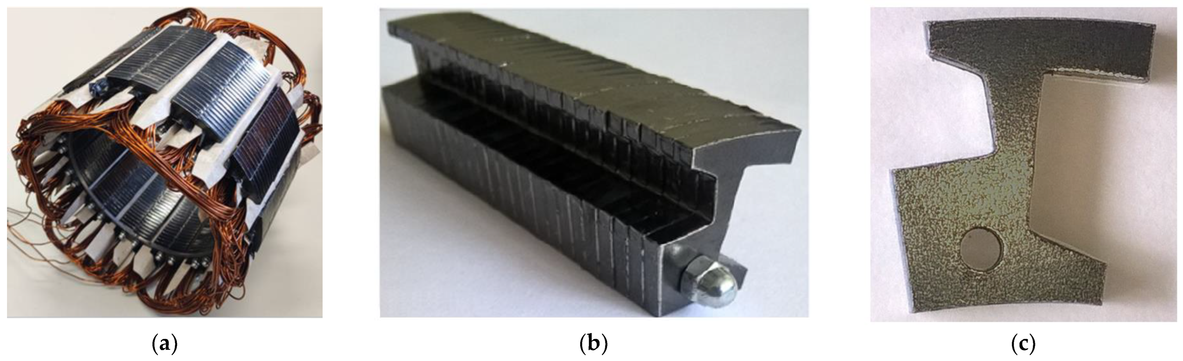
Figure 1a shows the first prototype of the MFC which was built with a new design concept. The concentrator consists of a multi-module core and windings to excite a constant or time-varying magnetic field concentrated in a working space inside the concentrator. The presented design of the multi-module core includes twenty-four identical core’s stacks (
Figure 1b) consisting of ferromagnetic core components made of a sheet of steel. A single ferromagnetic core component is shown in
Figure 1c. The ferromagnetic core components formed in the manner shown in
Figure 1c enable the assembly of the multi-module core with 24 semi-open slots. One half of the slots are located from the inside of the core, and the other ones are located from the outside.
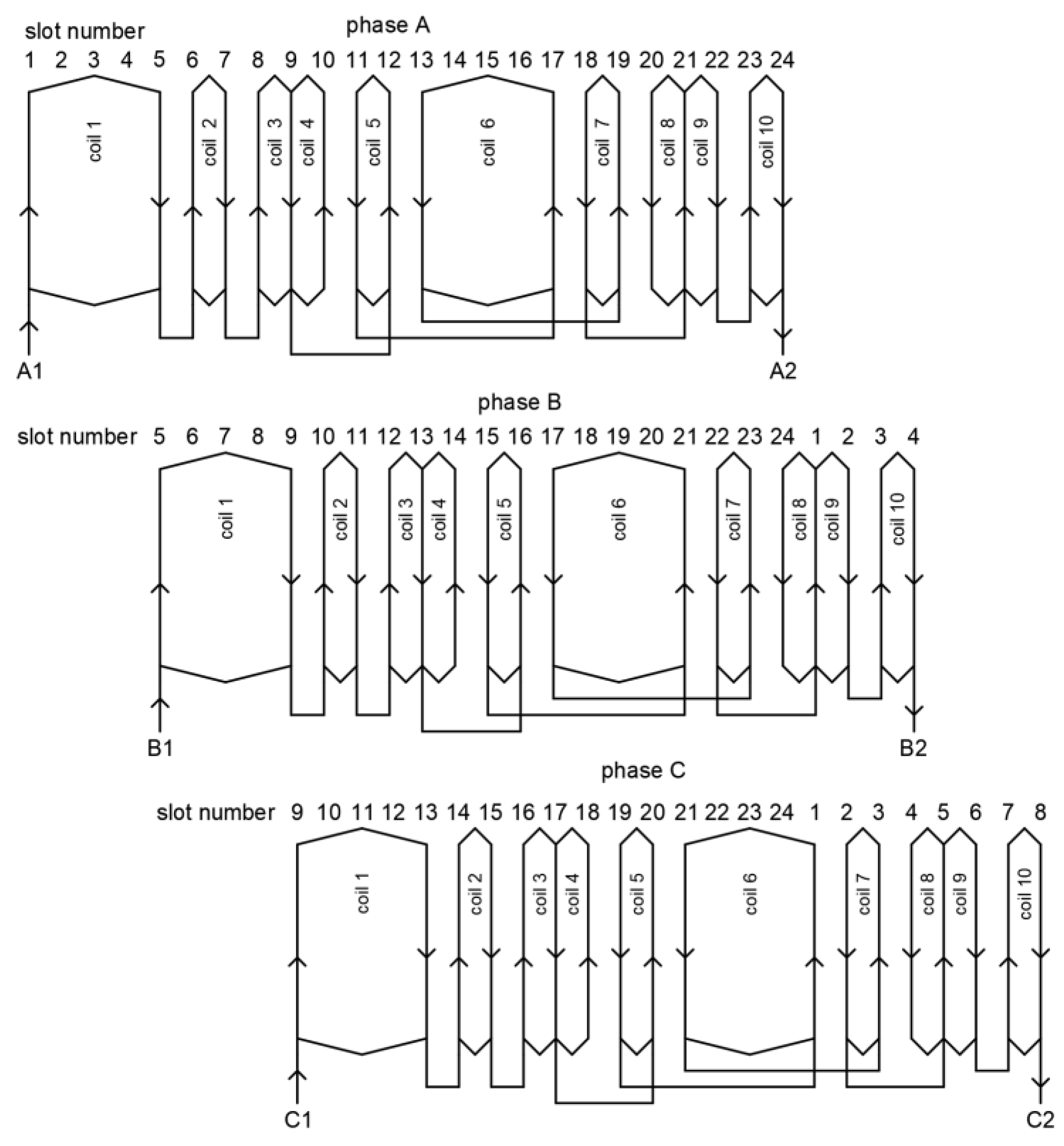
Coils are placed in the slots in a unique way to excite the magnetic field. The schematic diagram of the three-phase (A, B and C) windings for the presented electromagnetic field concentrator is shown in
Figure 2.
Presented in
Figure 2, a schematic diagram shows the unique arrangement of the windings located in the core’s slots numbered from 1 to 24. Each phase winding consists of ten coils connected in series. The coils of phase B in relation to the coils of phase A are arranged in the slots of the core in such a way that the angle of the phase B winding axis in relation to the angle of the phase A winding axis is skewed at the mechanical angle of 120 deg. and that the phase C winding axis in relation to the angle of the phase A winding axis is skewed at the mechanical angle of 240 deg.
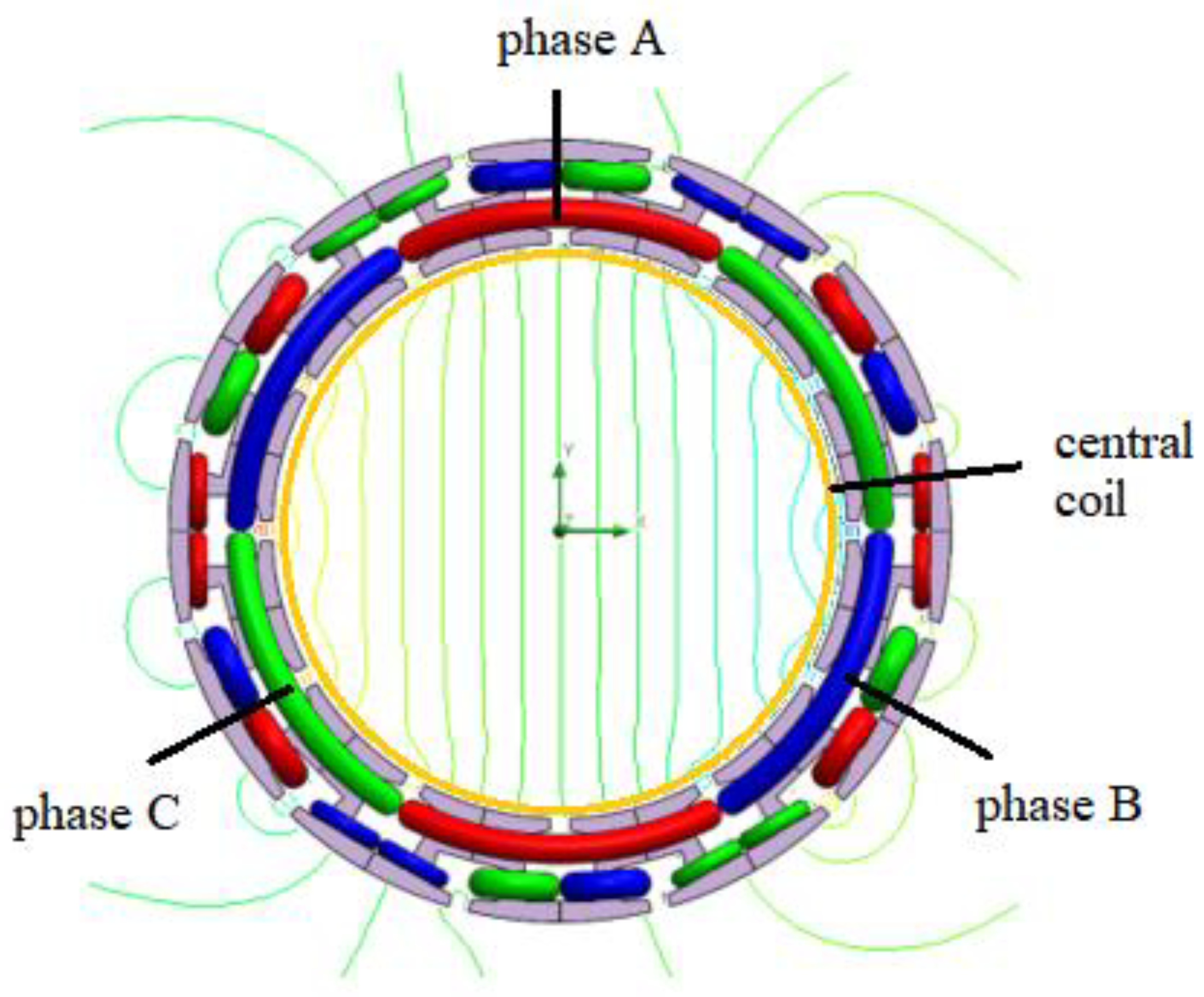
The windings are supplied with DC so that the current of the phase A winding is equal to
IA =
Inom and the currents of the phase B winding and the phase C winding are equal to
IB =
IC = −0.5
IA, where
Inom is the rated nominal current; this causes the excitation of a constant, uniform magnetic field in the working area inside the process chamber. The effect of excitation can be seen in
Figure 3, where flux lines arranged in accordance with the field distribution obtained by using 2D finite element (FE) methods are shown.
It should be added that supplying the windings with AC current in a three-phase system creates a rotating, uniform magnetic field inside the process chamber, where the magnitude of the vector magnetic field is proportional to the current and the vector magnetic field rotation frequency is 2πf, where f is the current pulsation. In addition, loading the central coil with DC causes the axial rotation of the vector magnetic field in the process chamber, and the vector magnetic field direction depends on the central coil’s current polarity. If the central coil is supplied with AC current, the vector magnetic field rotation frequency is proportional to the frequency of the AC central coil current.
3. Design Problem
It is of great interest to improve process chamber geometry by design optimization, thus reducing production costs and improving magnetic field distribution inside the chamber. In order to vary predefined variables in the initial design to search for the best geometry solution that reaches optimization goals, also taking into account further improvements, an optimization analysis using the Multi-Objective Genetic Algorithm (MOGA) was used in this case. The used algorithm is a hybrid variant of NSGA-II (Non-dominated Sorted Genetic Algorithm II) based on controlled elitism concepts. The procedure for setting up an optimization analysis using the MOGA (with Random Search) is presented below.
Table 1 shows the parameters that are used during optimization analysis.
The main geometrical dimensions of cores
R1 and
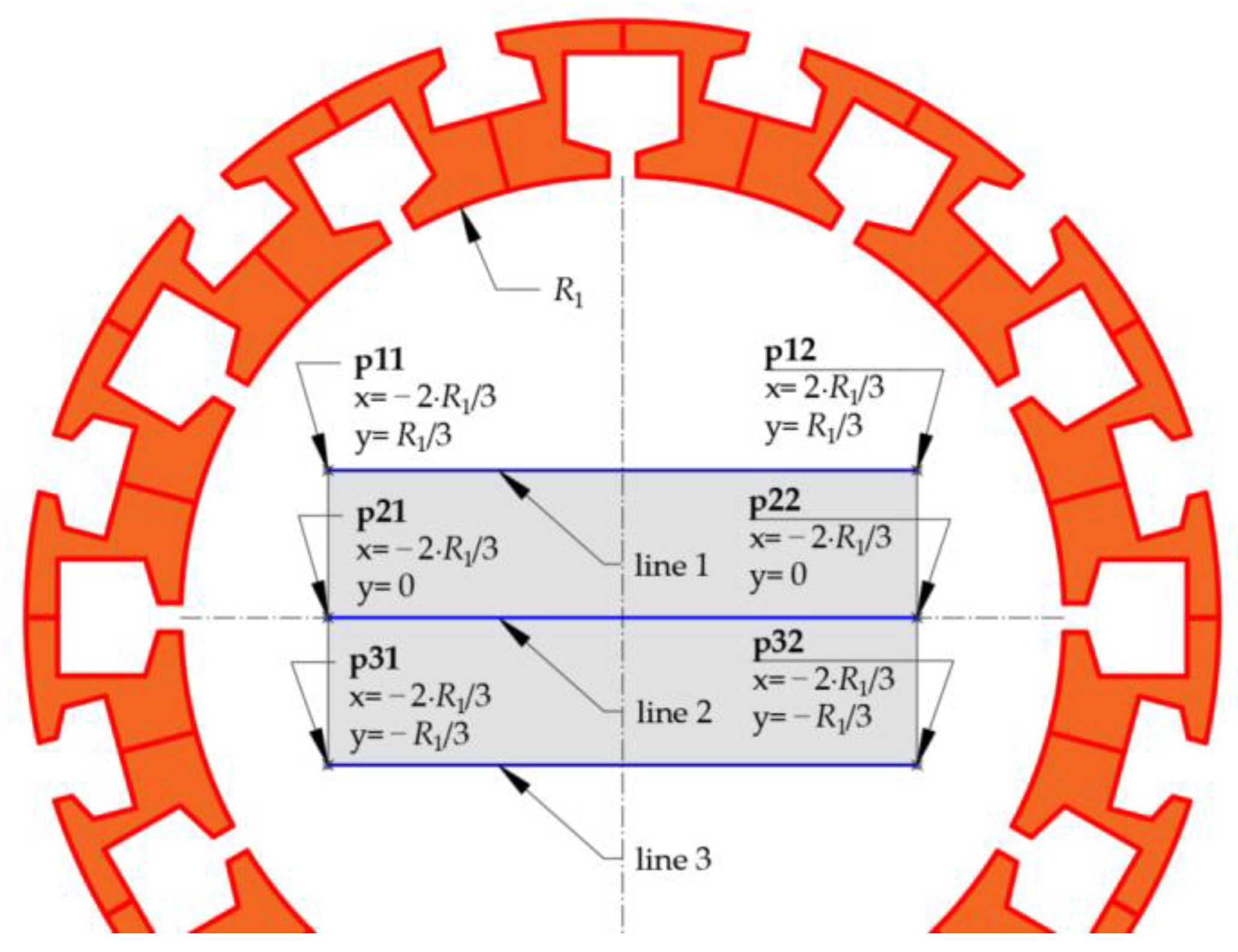
R2 were fixed in this study, and the design problem consisted in identifying other crucial dimensions of the cores’ slots, so that the magnetic flux density inside the process chamber could be maximized. For a vector of selected geometrical design variables
x, the following objective function is defined:
The above needs to be maximized with respect to
x, with
being the mean value of the magnitude of the vector magnetic flux density
By component calculated from vectors drawn along a center line (line 2), as shown in
Figure 4.
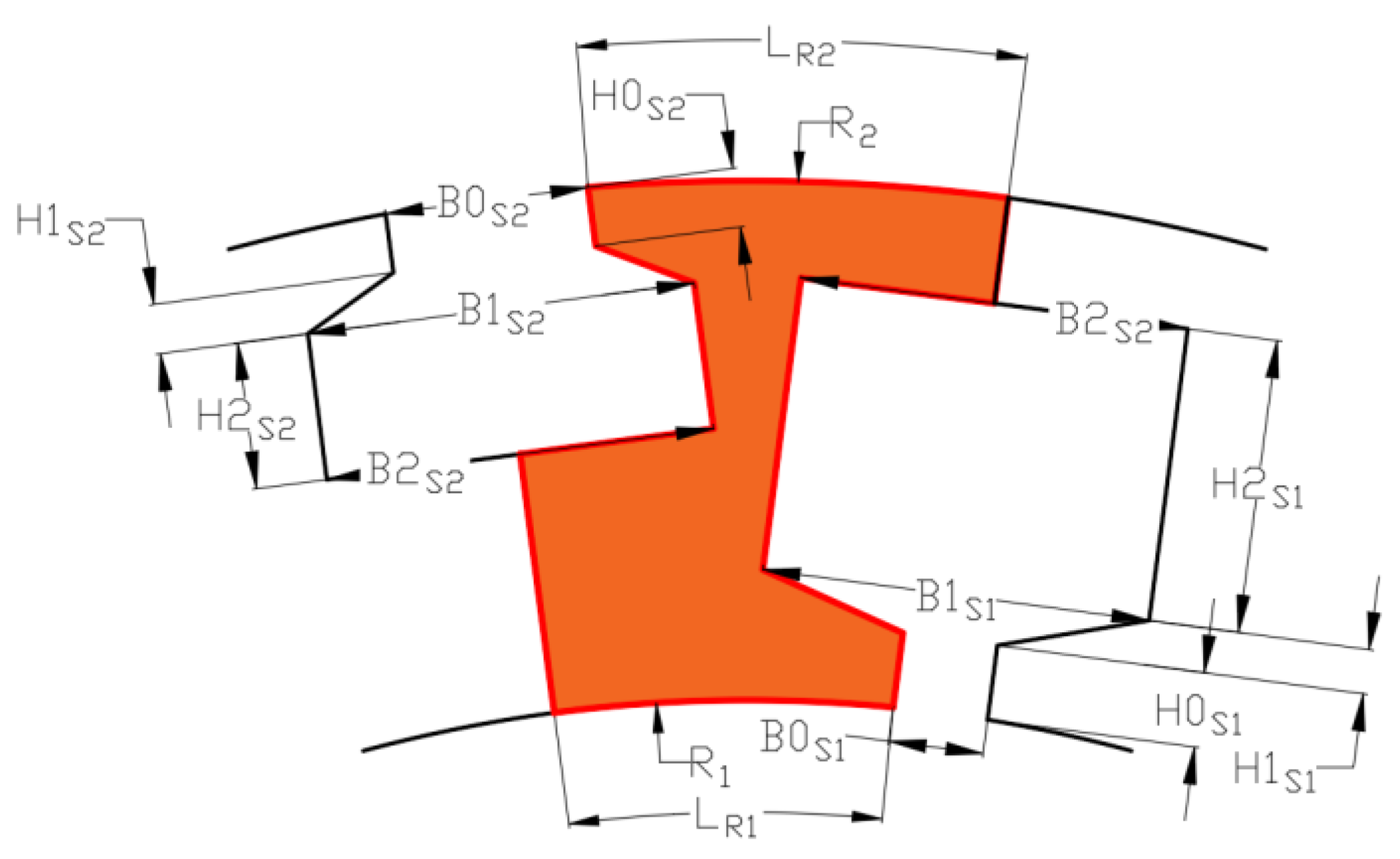
According to the problem formulation, a vector of design variables
x is defined:
x = (
,
,
,
,
,
,
,
). The dimensioning of the ferromagnetic core component is shown in
Figure 5.
In order to solve the problem numerically, optimization tools—Optimetrics coupled with Ansys Electronics 2021 R2—were applied.
As mentioned above, the purpose of the study is to find the optimal
x variable values at which the excitation of the magnetic field in the chamber is the most effective. In this study, we assumed that the maximal current density in the coils is limited to
J = 10 A/mm
2. The optimization was carried out under current load conditions in such a way that the current density of the phase A winding was
JA = 10 A/mm
2 and the current densities of phase B and phase C were
JB =
JC = 5 A/mm
2. During the definition of the current load of the coils, a copper filling factor
kc was taken into account. In this case,
kc was equal to 0.6. Moreover, noting practical considerations and requirements, the geometry of the chamber was optimized after taking into account the assumption that the inner and outer radii of the core were specified. The value of the minimum inner radius
R1 was equal to 120.0 mm, and the maximum outer radius of the chamber core
R2 was equal to 162.0 mm. Hence, in this case, the dimensions of the slots were optimized. When creating the initial model, except for dimensions
R1 and
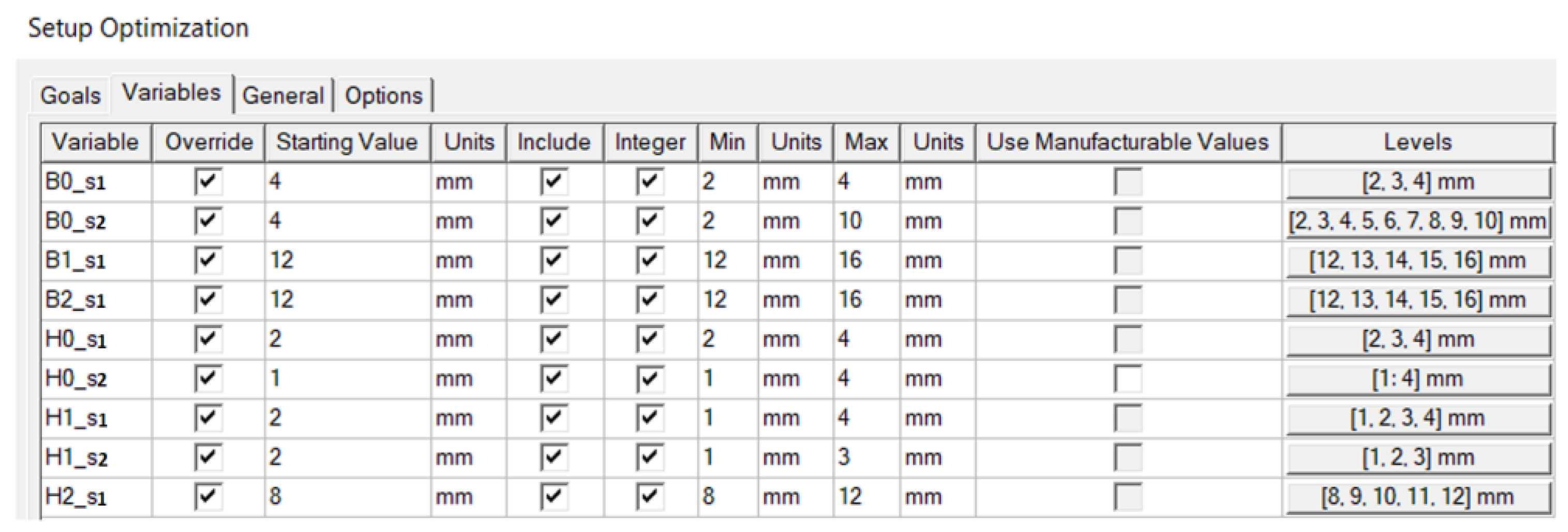
R2, the values of all variables were set randomly. An additional assumption was that all variable values had been limited to integers. The setup optimization details of the optimization variables are shown in
Figure 6.
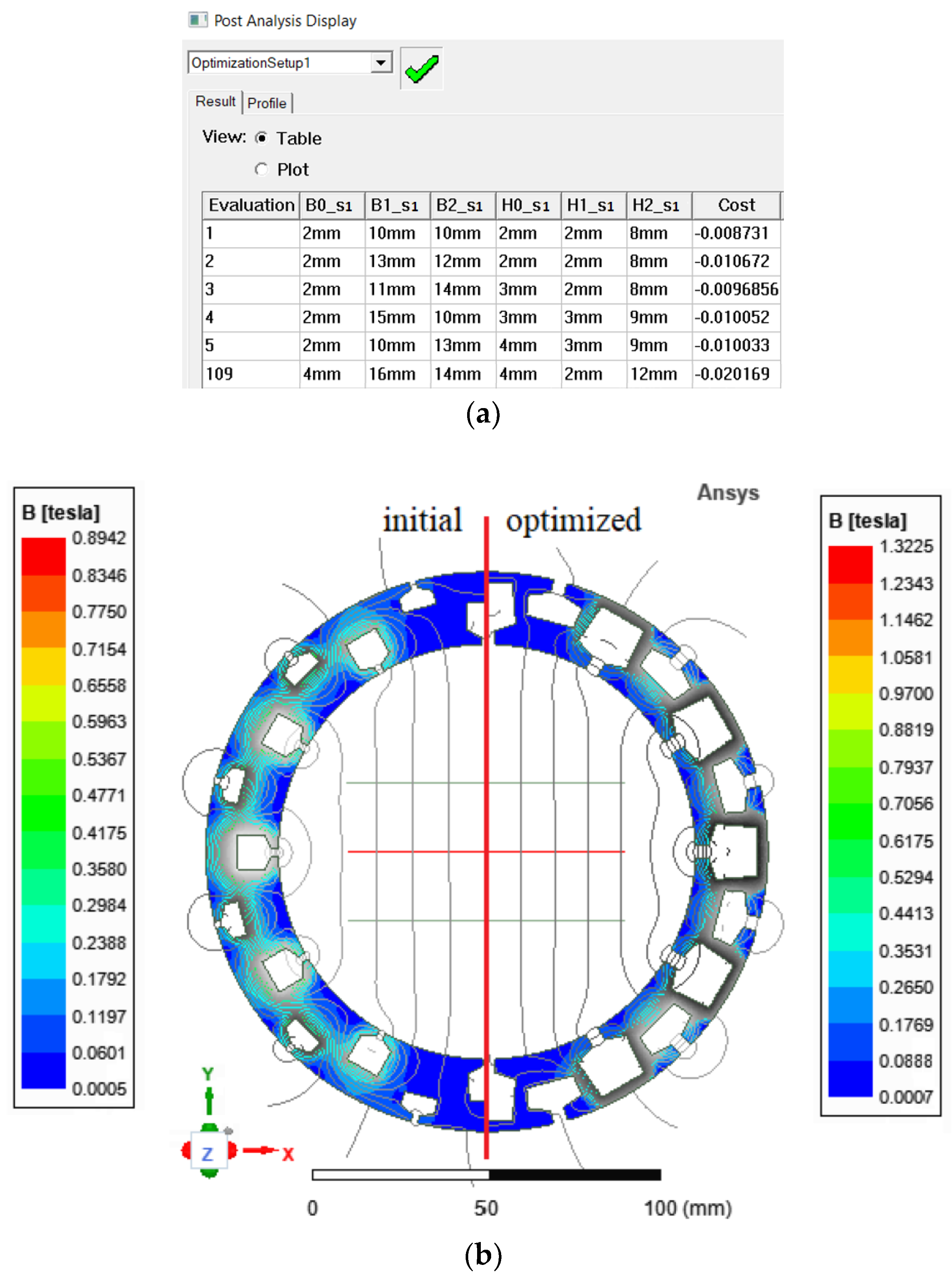
Optimization Results
Figure 7a shows a post-analysis display where the variable values calculated in the first five (1–5) evolutions, and the final (109) evolution can be seen.
Figure 7b shows a comparison of the views of two cores before and after ferromagnetic core component optimization.
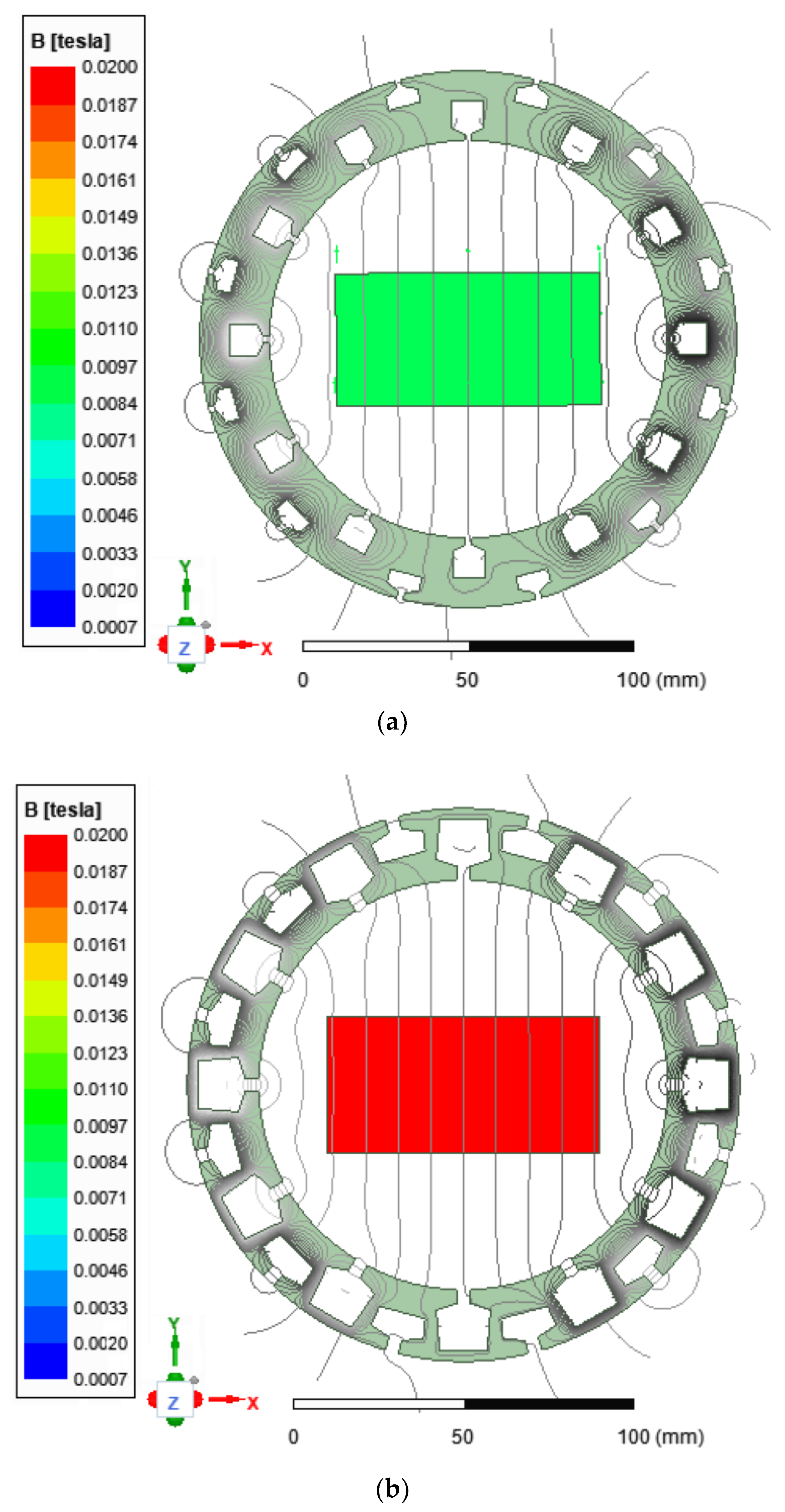
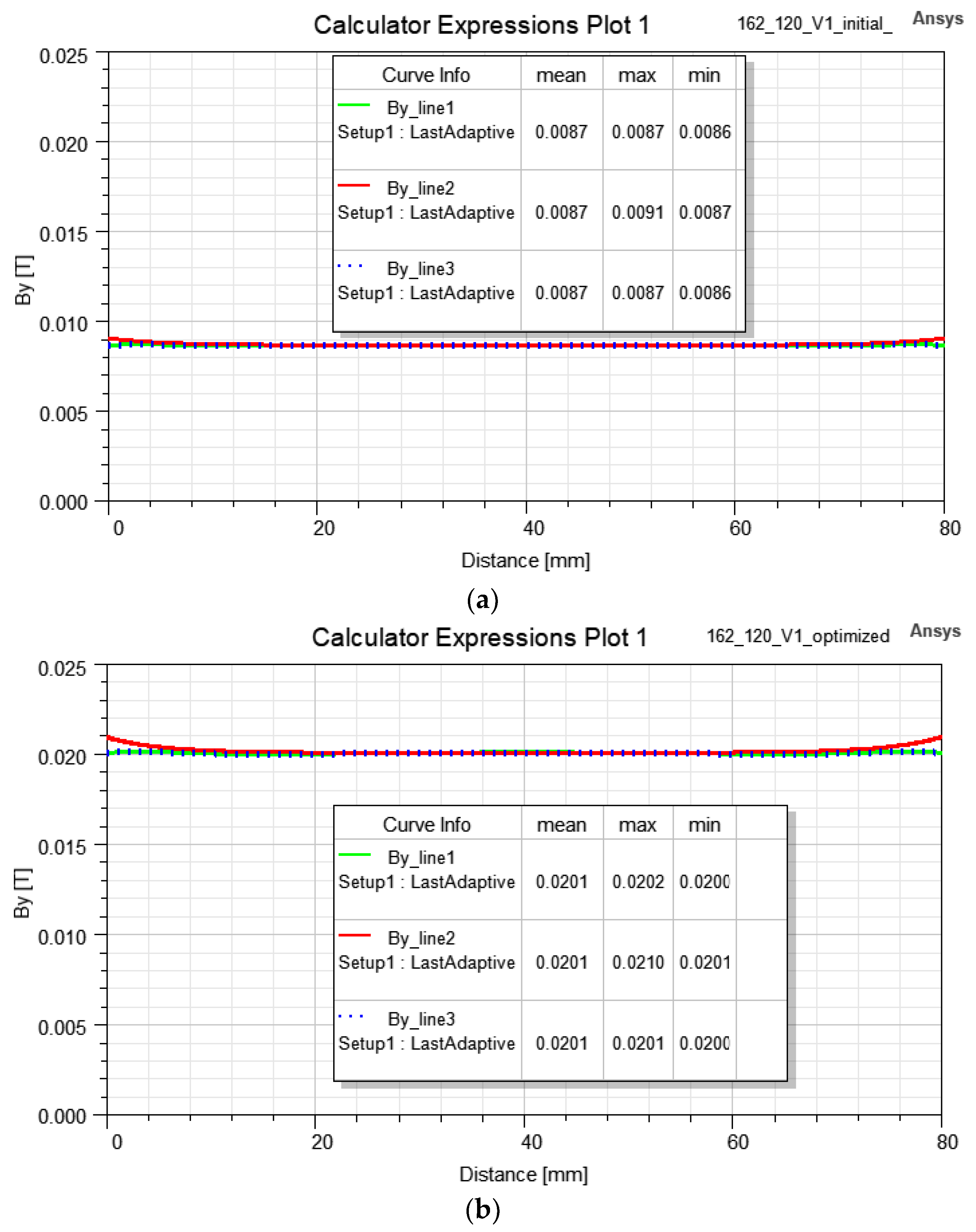
To show the effect of magnetic field concentration inside the process chamber, two-dimensional field models with a working area of 80 × 40 mm (width × height) dimensions were performed. The distribution of lines magnetic field inside the concentrator and magnetic flux density calculated on the surface working area are presented in
Figure 8. The results show that the optimized model (
Figure 8b) enables a much better strengthening (at least two times) of the magnetic field inside the concentrator in comparison to the initial model (
Figure 8a).
Figure 9 shows the characteristics of the vector magnetic flux density
By component magnitude versus the distance from line 1, line 2 and line 3 according to
Figure 4.
Additionally, in
Table 2, the maximum (
Bmax) and minimum (
Bmin) values of the magnitude of the vector magnetic flux density B
y component calculated on lines 1–3 and the mean value of the vector (
Bmean) calculated from vectors drawn along these lines are compared.
The presented results show that the value of the magnitude of vector magnetic flux density can achieve at least 20.0 mT with the expected uniformity of the magnetic field distribution in the entire working area of the chamber with optimized core geometry. The results show that in the optimized model, the average values of the magnitude of vector magnetic flux density Bmean determined on lines 1–3 are equal and that the maximum and minimum values differ by only 0.2 mT, which is 1% of the mean value.
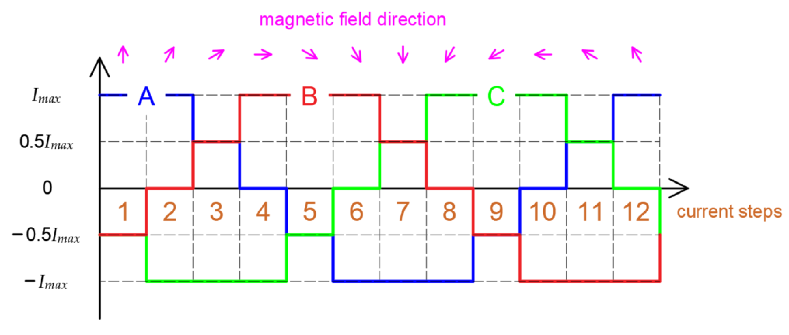
4. Vector Magnetic Field Orientation Current Control Method
Figure 10 shows the algorithm for a three-phase, 12-step DC control strategy. As you can see in the figure, each phase’s current should be discretized in the presented way, which allows one to obtain 12 different magnetic field distributions with specified vector magnetic field orientation in the process chamber.
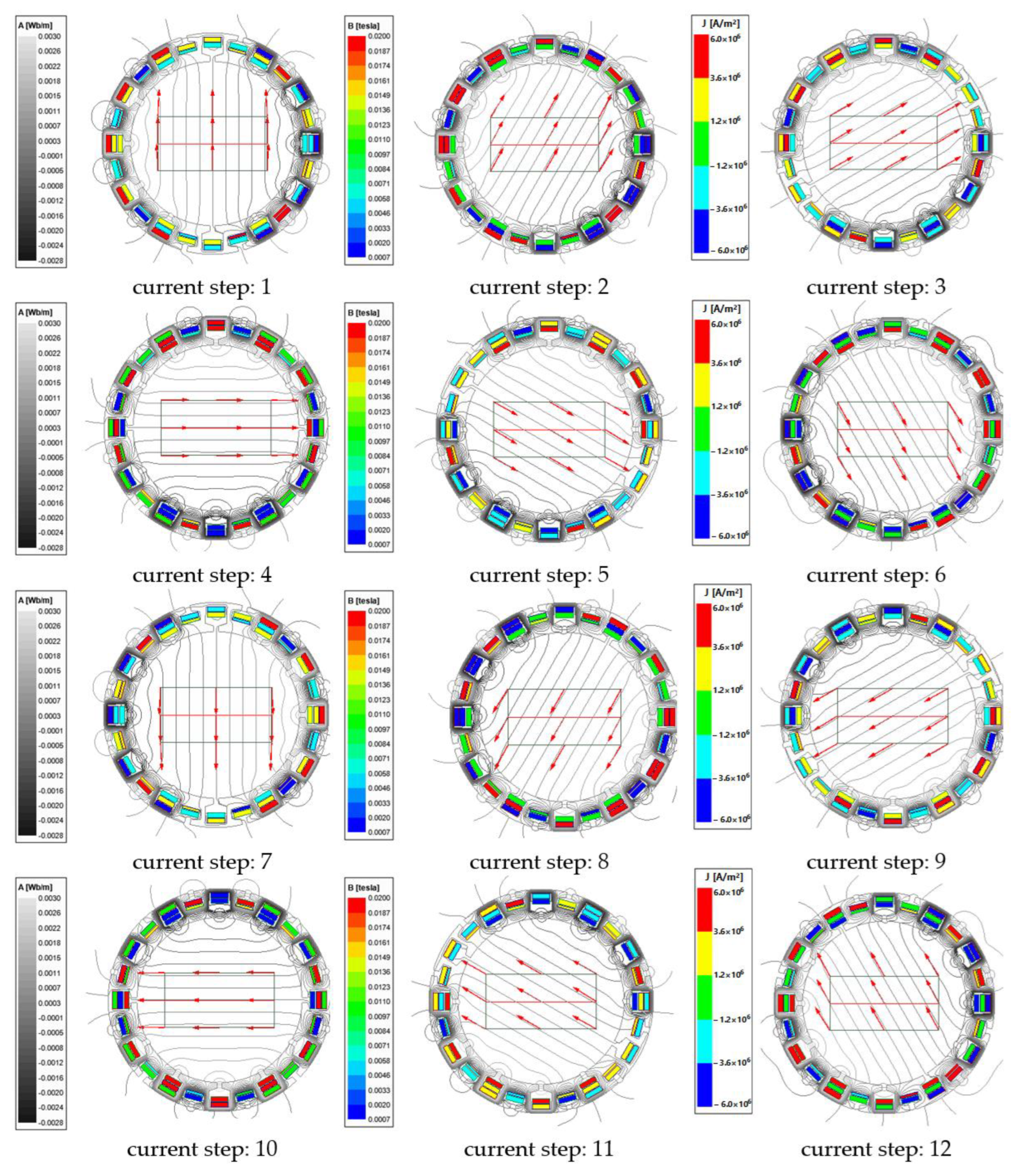
For validation, the presented DC control strategy for vector magnetic field orientation inside the process chamber at 12 current steps was implemented as shown in
Figure 11.
The presented results are relevant and show that the distribution of the lines of the magnetic field inside the concentrator and the vector magnetic flux (red arrows in
Figure 11) calculated on the surface working area for each of the DC control steps are correct. Thanks to the unique arrangement of the three-phase windings and the current control strategy, it is possible not only to orient the vector magnetic field but also to maintain its magnitude throughout the working area.
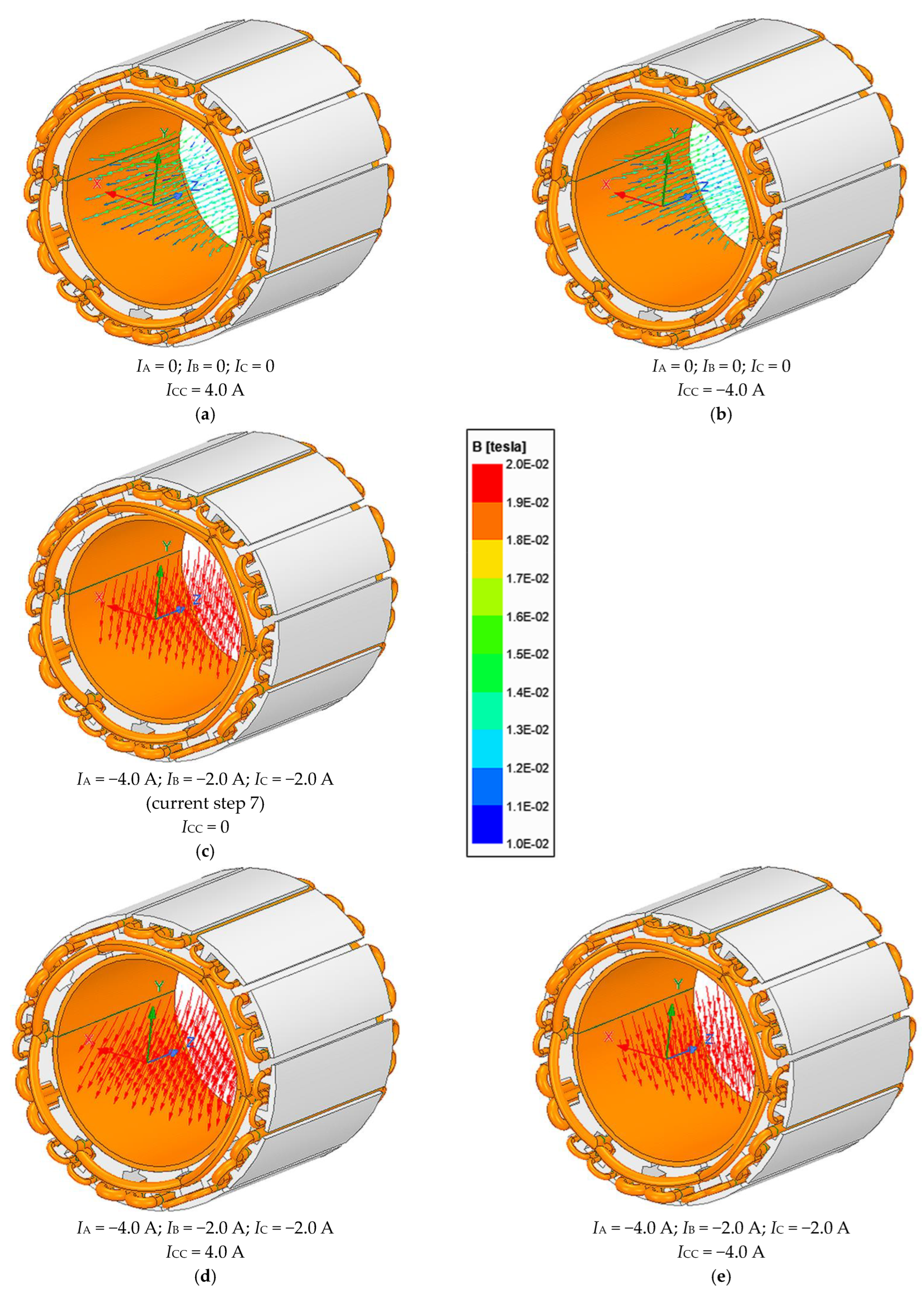
In order to confirm the possibility of directing the vector magnetic field along the axial direction of the concentrator, a 3D model of the concentrator was developed.
Figure 12 shows four cases of vector magnetic field orientation calculated in the chamber work area. The presented results clearly show that the vectors of the magnetic field visible in the drawings excited by the central coil current
ICE only (
Figure 12a,b) have axial orientation, while the three-phase windings supplying (
Figure 12d,e) the vector magnetic field rotate in the direction according to the step current control algorithm. Additionally,
Figure 12c shows the vector magnetic field orientation at current step 7 achieved at no-load central coil current.
The obtained simulation results clearly show that depending on the polarity of the central coil current, it is possible to freely orient the vector magnetic field along the axial direction. Additionally, by DC steps or the sinusoidal supply of three-phase windings, the magnetic field inside the chamber can be excited in a given magnetic field orientation with good uniformity.
5. Experimental Results
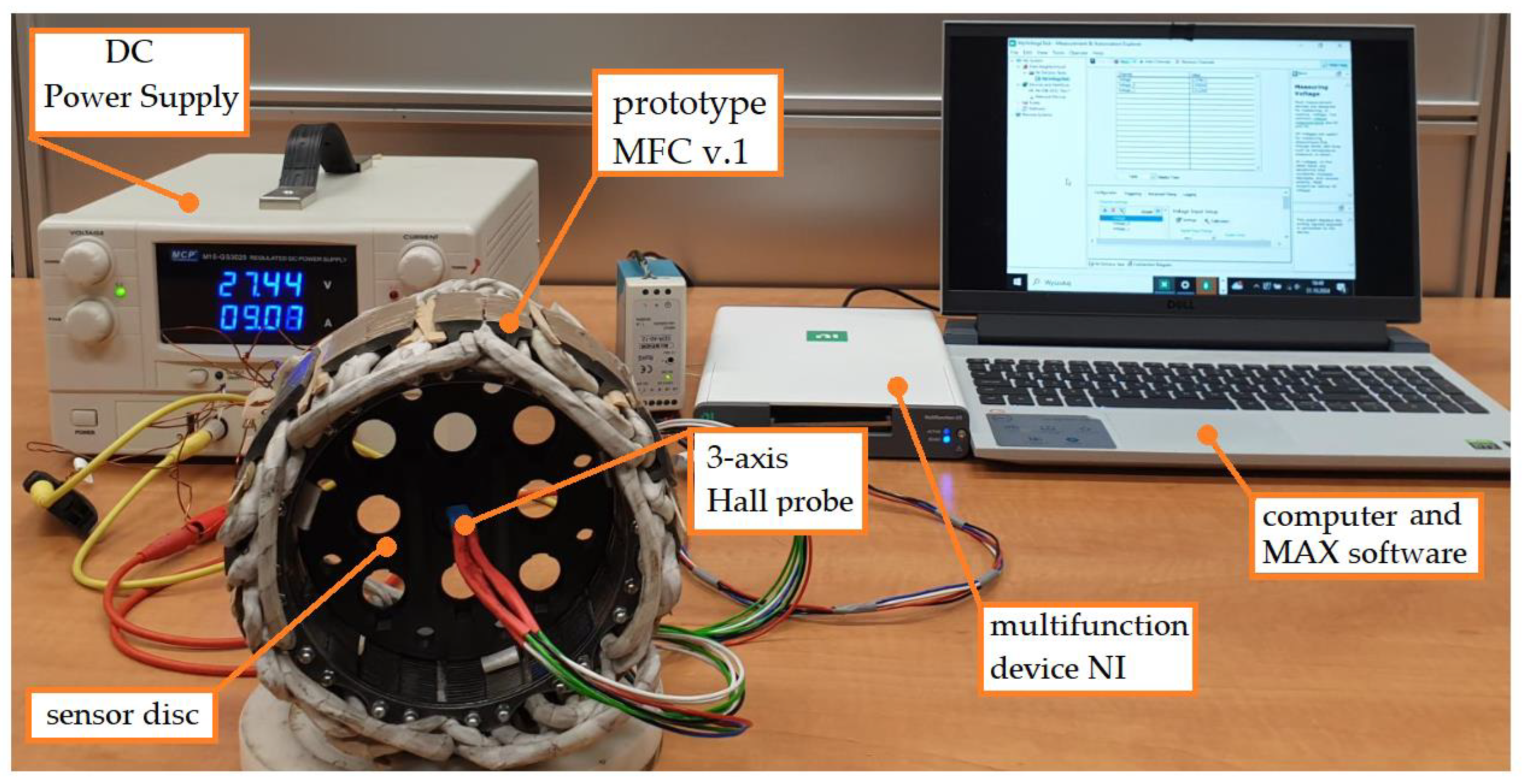
In order to confirm the effectiveness of generating a uniform magnetic field in the working area inside the process chamber under real conditions, a prototype of a magnetic field concentrator and a test stand were developed and built.
Figure 13 shows that the stand consisted of a first prototype of the MFC (called MFC v.1); DC power supply; a multifunction device, with, among others, 32 analog inputs (16-Bit,1.25 MS/s); Measurement & Automation Explorer (MAX version 2024 Q2) installed on a computer to configure NI hardware and software, as well as view instruments and analog signals connected to a measuring system; and a three-axis Hall probe, which is located in the middle of the holes of a sensor disc (nine points numbered as p11, p12, p13, p21, p22, p23, p31, p32 and p33 according to
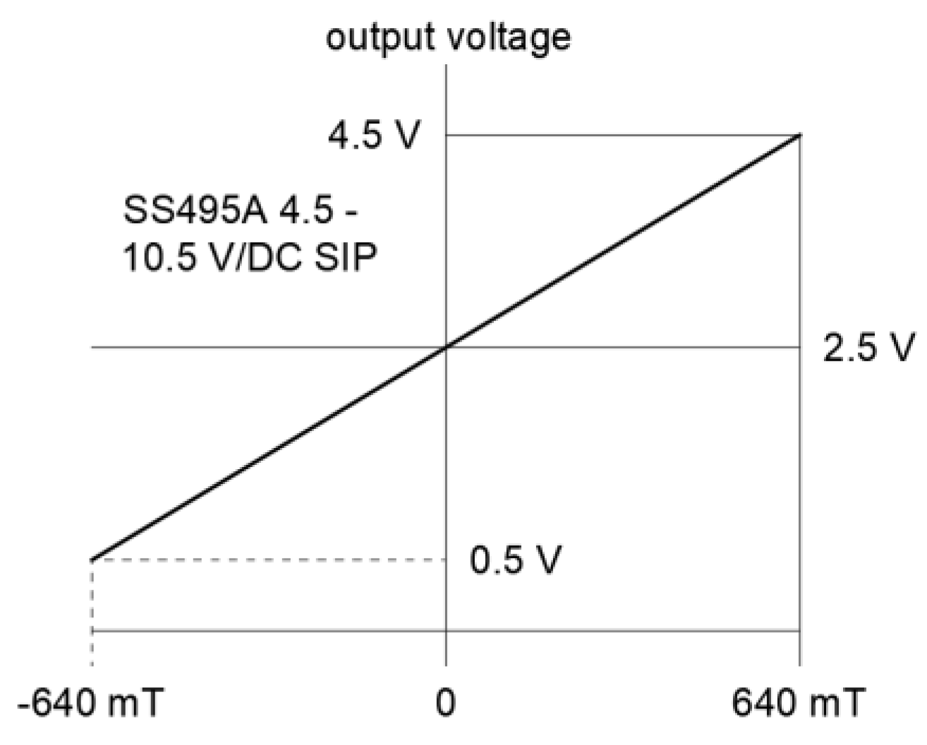
Figure 4). The three-axis Hall probe consist of three miniature ratiometric linear Hall effect sensors (SS495 series), whose transfer characteristics are shown in
Figure 14.
It should be noted that the presented prototype, MFC v.1, consists of a multi-module core made of a 3.0 mm thick steel sheet and three-phase windings, and it does not yet include the central coil. Moreover, in this case, the copper filling factor of the three-phase windings
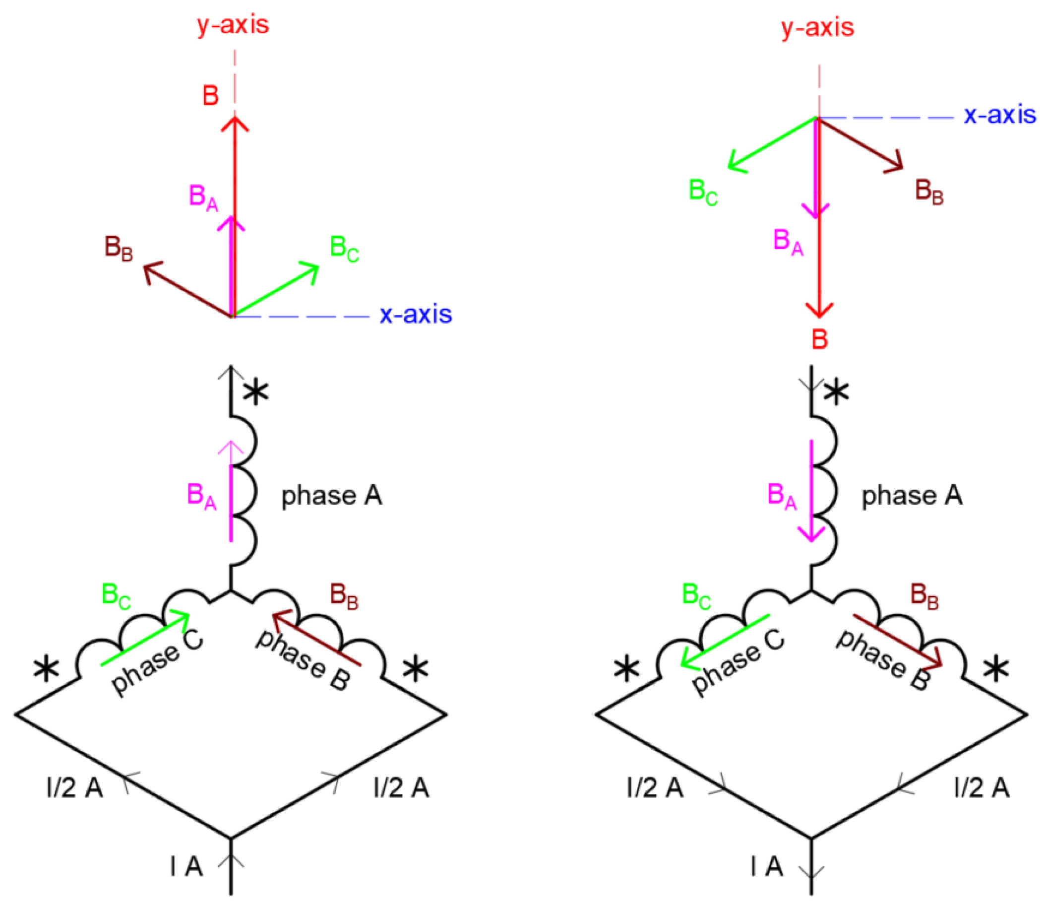
kc is approx. only 0.2, and this, unfortunately, does not allow for a direct comparison of simulation and experimental results. However, the results of experimental studies will allow for the verification of theoretical assumptions regarding magnetic field excitation by the MFC v.1 prototype. Hence, first, current load tests were carried out on the prototype, where the three-phase windings were connected in a star (Y-type) according to
Figure 15, and the windings were supplied with DC. The windings were connected for evaluating the performance of the excitation by the MFC in such a way that the magnetic field excitation inside the chamber was generated with a field distribution corresponding to current step 1 or current step 7 (depending on the polarity of the current) according to
Figure 11.
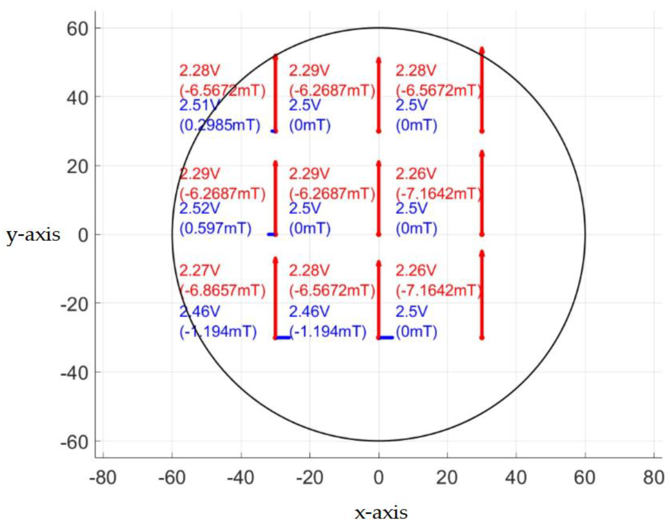
Figure 16 shows the values of the Hall probe terminal voltage and the corresponding values of the vector magnetic flux density
Bx and
By components measured inside the MFC halfway along the core at nine points, which belonged to the ends of lines 1–3 according to
Figure 4, by supplying the windings with DC so that the current of phase A was equal to
IA = 9 A and the currents of phase B and phase C were equal to
IB =
IC = −0.5
IA = −4.5 A.
6. Discussion
Devices that generate a homogeneous magnetic field with adjustable values are still needed because they would allow us to perform scientific research in many areas of science and technology. This article presents the results of a modular yet flexible magnetic field concentrator design with electromagnetic excitation which has been made in an unconventional, previously unknown way. What is unique is that the presented design can be successfully adapted to a process chamber of any dimensions. Moreover, an effective method for device optimization by using the 2D FE method and the genetic algorithm has been developed and presented in detail. The simulation and initial experimental results confirmed that it is possible to build a magnetic field concentrator with good features in terms of vector magnetic field orientation and magnetic field pulsation abilities, where the magnetic field can be electrically adjusted, and this can find many practical applications. The presented field concentrator can be used in devices carrying out chemical, biological, thermal and measurement processes, among many others. It should be added that in some applications, especially in biological research, it will be a big challenge to maintain a constant, relatively low temperature inside the process chamber. Therefore, future research will also be focused on increasing the power density of the device and developing effective cooling systems for the concentrator.
7. Conclusions
In this paper, selected design works of an electromagnetic field concentrator for process chambers are presented. On the basis of 2D FE analysis results, it was confirmed that the presented geometry, construction method, dedicated three-phase windings, central coil and suitable current control supplying strategy of the electromagnetic field concentrator enable the construction of a process chamber in a new way, where steady or time-varying magnetic fields can be excited with adjustable intensity and controlled pulsation. Additionally, on the basis of preliminary experimental results, taking into account the inaccuracy of the device’s workmanship, the defects in the presented sensor-positioning method and the not optimally selected range of magnetic field measurement, it can be concluded that the measured values of the magnetic field are consistent with expectations. The presented results clearly show that quite good uniformity of the magnetic field in the working area inside the prototype has been successfully achieved. The presented prototype does not have a specific application. It can be used in many applications where a process chambers is used, where a homogeneous magnetic field is required, and where the magnetic field can be static, time-varying and/or rotating.
8. Patents
The results of the work reported in this manuscript are the subject of a patent application to the Patent Office of the Republic of Poland for granting a patent for the invention (application No. P.448503).
Author Contributions
Conceptualization, P.P. and P.S.; methodology, P.P. and P.S.; software, P.P. and P.S.; validation, P.P. and P.S.; formal analysis, P.P. and P.S.; investigation, P.P. and P.S.; resources, P.P. and P.S.; data curation, P.P. and P.S.; writing—original draft preparation, P.P. and P.S.; writing—review and editing, P.P. and P.S.; visualization, P.P. and P.S.; supervision, P.P. and P.S. All authors have read and agreed to the published version of the manuscript.
Funding
This research received no external funding.
Data Availability Statement
Data are contained within the article.
Conflicts of Interest
The authors declare no conflicts of interest.
References
- Rosen, A.D. Mechanism of action of moderate—Intensity static magnetic fields on biological systems. Cell Biochem. Biophys. 2003, 39, 163–173. [Google Scholar] [CrossRef] [PubMed]
- Mardinoglu, A.; Cregg, P.J.; Murphy, K.; Prina–Mello, A. Theoretical modeling of physiologically stretched vessel in magnetisable stent assisted magnetic drug targeting application. J. Magn. Magn. Mater. 2011, 323, 324–329. [Google Scholar] [CrossRef]
- Hughes, S.; El Haj, A.J.; Dobson, J.; Martinac, B. The influence of static magnetic fields on mechanosensitive ion channel activity in artificial liposomes. Eur. Biophys. J. 2005, 34, 461–468. [Google Scholar] [CrossRef]
- Ciecholewska-Juśko, D.; Żywicka, A.; Junka, A.; Woroszyło, M.; Wardach, M.; Chodaczek, G.; Szymczyk-Ziółkowska, P.; Migdał, P.; Fijałkowski, K. The effects of rotating magnetic field and antiseptic on in vitro pathogenic biofilm and its milieu. Sci. Rep. 2022, 12, 8836. [Google Scholar] [CrossRef] [PubMed]
- Kwiatkowski, P.; Tabiś, A.; Fijałkowski, K.; Masiuk, H.; Łopusiewicz, Ł.; Pruss, A.; Sienkiewicz, M.; Wardach, M.; Kurzawski, M.; Guenther, S. Regulatory and enterotoxin gene expression and enterotoxins production in Staphylococcus aureus FRI913 cuztures exposed to a rotating magnetic field and trans-anethole. Int. J. Mol. Sci. 2022, 23, 6327. [Google Scholar] [CrossRef] [PubMed]
- Jabłońska, J.; Augustyniak, A.; Kordas, M.; Dubrowska, K.; Sołoducha, D.; Borowski, T.; Konopacki, M.; Grygorcewicz, B.; Roszak, M.; Dołęgowska, B.; et al. Evaluation of ferrofluid-coated rotating magnetic field-assisted bioreactor for biomass production. Chem. Eng. J. 2022, 431, 133913. [Google Scholar] [CrossRef]
- Antosiewicz, T.J.; Wrobel, P.; Szoplik, P. Magnetic field concentrator for probing optical magnetic metamaterials. Opt. Express 2010, 18, 25906–25911. [Google Scholar] [CrossRef] [PubMed]
- Zhang, Z.Y.; Matsumoto, S.; Choi, S.; Teranishi, R.; Kiyoshi, T. A new structure for a magnetic field concentrator using NbTi sheet superconductors. Phys. C Supercond. Its Appl. 2011, 71, 1547–1549. [Google Scholar] [CrossRef]
- Zhang, P.; Kimchi, M.; Shao, H.; Gould, J.E.; Daehn, G.S. Analysis of the Electromagnetic Impulse Joining Process with a Field Concentrator. AIP Conf. Proc. 2004, 712, 1253. [Google Scholar] [CrossRef]
- Bondarenko, S.I.; Shablo, A.A.; Pavlov, P.P.; Perepelkin, S.S. Ferromagnetic concentrator of a magnetic field for the planar HTSC SQUID. Phys. C Supercond. Its Appl. 2002, 372–376, 158–161. [Google Scholar] [CrossRef]
- Wrobel, P.; Antosiewicz, T.J.; Stefaniuk, T.; Szoplik, T. Plasmonic concentrator of magnetic field of light. J. Appl. Phys. 2012, 112, 074304. [Google Scholar]
- Woroszyło, M.; Ciecholewska-Jusko, D.; Junka, A.; Wardach, M.; Chodaczek, G.; Szymczyk-Ziółkowska, P.; Migdał, P.; Fijałkowski, K. Rotating Magnetic Field increases β-lactam antibiotic susceptibility of methicillin-resistant Staphylococcus aureus strains. Int. J. Mol. Sci. 2021, 25, 8836. [Google Scholar] [CrossRef]
- Glinka, M.; Gawron, S.; Sieron, A.; Pawlowska–Goral, K. Test chambers for cell culture in static magnetic field. J. Magn. Magn. Mater. 2013, 331, 208–215. [Google Scholar] [CrossRef]
- Vokoun, D.; Tomassetti, G.; Beleggia, M.; Stachiv, I. Magnetic forces between arrays of cylindrical permanent magnets. J. Magn. Magn. Mater. 2011, 323, 55–60. [Google Scholar] [CrossRef]
- Huong Giang, D.T.; Tam, H.A.; Ngoc Khanh, V.T.; Vinh, N.T.; Anh Tuan, P.; Van Tuan, N.; Thi Ngoc, N.; Duc, N.H. Magnetoelectric Vortex Magnetic Field Sensors Based on the Metglas/PZT Laminates. Sensors 2020, 20, 2810. [Google Scholar] [CrossRef] [PubMed]
- Dong, S.X.; Bai, J.G.; Zhai, J.Y.; Li, J.F.; Lu, G.Q.; Viehland, D.; Zhang, S.J.; Shrout, T.R. Circumferential-mode, quasi-ring-type, magnetoelectric laminate composite—A highly sensitive electric current and/or vortex magnetic field sensor. Appl. Phys. Lett. 2005, 86, 182506. [Google Scholar]
- Giang, D.T.H.; Duc, P.A.; Ngoc, N.T.; Hien, N.T.; Duc, N.H. Spatial angular positioning device with three-dimensional magnetoelectric sensors. Rev. Sci. Instrum. 2012, 83, 095006. [Google Scholar] [PubMed]
- Le, M.-Q.; Belhora, F.; Cornogolub, A.; Cottinet, P.-J.; Lebrun, L.; Hajjaji, A. Enhanced magnetoelectric effect for flexible current sensor applications. J. Appl. Phys. 2014, 115, 194103. [Google Scholar]
- Bichurin, M.; Petrov, R.; Sokolov, O.; Leontiev, V.; Kuts, V.; Kiselev, D.; Wang, Y. Magnetoelectric magnetic field sensors: A review. Sensors 2021, 21, 623. [Google Scholar] [CrossRef] [PubMed]
Figure 1.
A new concept for a magnetic field concentrator: (a) prototype; (b) single stack of cores; (c) ferromagnetic core component.
Figure 1.
A new concept for a magnetic field concentrator: (a) prototype; (b) single stack of cores; (c) ferromagnetic core component.
Figure 2.
Schematic diagram of 3-phase (A, B and C) windings.
Figure 2.
Schematic diagram of 3-phase (A, B and C) windings.
Figure 3.
Magnetic field lines observed on the cross-section surface.
Figure 3.
Magnetic field lines observed on the cross-section surface.
Figure 4.
Principle of creating calculation lines (line 1, line 2 and line 3).
Figure 4.
Principle of creating calculation lines (line 1, line 2 and line 3).
Figure 5.
Dimensioning of ferromagnetic core component.
Figure 5.
Dimensioning of ferromagnetic core component.
Figure 6.
Optimization variables.
Figure 6.
Optimization variables.
Figure 7.
Post-optimized results: (a) View of post-analysis display. (b) Core geometry and magnetic field distribution in the model before and after optimization, in comparison.
Figure 7.
Post-optimized results: (a) View of post-analysis display. (b) Core geometry and magnetic field distribution in the model before and after optimization, in comparison.
Figure 8.
Magnetic flux density on the surface working area: (a) Initial model. (b) After optimization, in comparison.
Figure 8.
Magnetic flux density on the surface working area: (a) Initial model. (b) After optimization, in comparison.
Figure 9.
Characteristics of vector magnetic flux density By component magnitude versus distance from line 1, line 2 and line 3: (a) Initial model. (b) After optimization, in comparison.
Figure 9.
Characteristics of vector magnetic flux density By component magnitude versus distance from line 1, line 2 and line 3: (a) Initial model. (b) After optimization, in comparison.
Figure 10.
Orientation of vector magnetic field with 3-phase, 12-step DC control strategy.
Figure 10.
Orientation of vector magnetic field with 3-phase, 12-step DC control strategy.
Figure 11.
Vector magnetic field orientation inside the process chamber on the surface working area at 12 current steps.
Figure 11.
Vector magnetic field orientation inside the process chamber on the surface working area at 12 current steps.
Figure 12.
Vectors of magnetic field excited inside chamber for 5 selected cases: (a) Icc > 0, IABC = 0; (b) Icc < 0, IABC = 0; (c) Icc = 0, IABC > 0; (d) Icc > 0, IABC > 0; (e) Icc < 0, IABC > 0.
Figure 12.
Vectors of magnetic field excited inside chamber for 5 selected cases: (a) Icc > 0, IABC = 0; (b) Icc < 0, IABC = 0; (c) Icc = 0, IABC > 0; (d) Icc > 0, IABC > 0; (e) Icc < 0, IABC > 0.
Figure 13.
Test stand with prototype of magnetic field concentrator.
Figure 13.
Test stand with prototype of magnetic field concentrator.
Figure 14.
Transfer characteristics of linear Hall effect sensors (SS495 series) used in 3-axis Hall probe at 5.0 VDC supply volts.
Figure 14.
Transfer characteristics of linear Hall effect sensors (SS495 series) used in 3-axis Hall probe at 5.0 VDC supply volts.
Figure 15.
Three-phase winding connection diagram for testing purposes.
Figure 15.
Three-phase winding connection diagram for testing purposes.
Figure 16.
Values of Hall probe terminal voltage and the corresponding values of the vector magnetic flux density Bx (blue line) and By (red line) components.
Figure 16.
Values of Hall probe terminal voltage and the corresponding values of the vector magnetic flux density Bx (blue line) and By (red line) components.
Table 1.
Optimizer options.
Table 1.
Optimizer options.
| Parameters | Value |
|---|
| Number of initial samples | 100 |
| Number of samples per iteration | 50 |
| Maximum allowable pareto percentage | 70 |
| Convergence stability percentage | 10 × 10−4 |
| Maximum number of iterations | 20 |
| Mutation probability | 10 × 10−2 |
Table 2.
Selected values of magnitude of vector magnetic flux density By component on lines 1–3 calculated before and after optimization.
Table 2.
Selected values of magnitude of vector magnetic flux density By component on lines 1–3 calculated before and after optimization.
| | Line 1 | Line 2 | Line 3 |
|---|
| | Initial | Optimized | Initial | Optimized | Initial | Optimized |
|---|
| Bmean (mT) | 8.7 | 20.1 | 8.7 | 20.1 | 8.7 | 20.1 |
| Bmax (mT) | 8.7 | 20.2 | 9.1 | 21.0 | 8.7 | 20.1 |
| Bmin (mT) | 8.6 | 20.0 | 8.7 | 20.1 | 8.6 | 20.0 |
| Disclaimer/Publisher’s Note: The statements, opinions and data contained in all publications are solely those of the individual author(s) and contributor(s) and not of MDPI and/or the editor(s). MDPI and/or the editor(s) disclaim responsibility for any injury to people or property resulting from any ideas, methods, instructions or products referred to in the content. |
© 2024 by the authors. Licensee MDPI, Basel, Switzerland. This article is an open access article distributed under the terms and conditions of the Creative Commons Attribution (CC BY) license (https://creativecommons.org/licenses/by/4.0/).


