Abstract
Many countries have a variety of offshore and onshore wind turbines that face extreme aging challenges. Issues with harmful vibrations that must be minimized are addressed in this paper. A new method of wind turbine tower vibration control using piezoelectricity and shunt circuits is proposed in this paper. The passive vibration control method is shown to improve the tower’s structural performance under various environmental loads, like wind and seismic excitations. To examine the effectiveness of the suggested shunted piezoelectric system, a simple surrogate finite element model of a wind turbine tower is considered, and various investigations at the second eigenfrequency are carried out. An alternative way of modeling the studied structure is considered and the results demonstrate better performance. The advantages of setting up structural damping systems for decreasing tower vibrational loads and boosting their structural stability and resilience against extreme events are highlighted throughout this work.
1. Introduction
Wind turbines are exposed to extreme environments and loads which are responsible for the reduction of their structural health, lifespan, safety, and wind energy production. Numerous control techniques were explored in commercial wind turbines to reduce the influence of external environmental variables, namely vibrations. Vibration mitigation becomes a critical design issue for larger wind turbines with flexible pylons [1]. Vibrations, among others, influence fatigue, which is a critical design issue in wind energy structures. An example of methods for analyzing such vibrations, based on frequency response analysis, is studied in [2,3]. Specifically, the analysis showed that porous structure fractions can improve the adaptive characteristics of passive control systems utilized for vibration-reducing applications in the low and intermediate frequency ranges for unmanned aerial vehicles. Furthermore, active or classical tuned mass or liquid dampers have been proposed for vibration suppression, which are quite inflexible and expensive solutions as it is described in detail in [4]. This review includes a wide variety of vibration control strategies related to passive, active, and semi-active control approaches, with an overview of the current developments in innovative features and studies of wind turbine tower performance under different environmental loads, such as wind, waves, currents, and seismic excitations. The research work of Machado et al. [5] presents an updated evaluation of wind turbine vibration challenges and control solutions, including advances from 2015 to the present. From this paper, active and semi-active strategies are primarily used to reduce vibrations in the drivetrain, blade, and nacelle, while passive approaches are applied to the tower, support structure, blades, and turbine. In [6], a down-scaled, simplified aircraft model is used to test and estimate the broadband vibration reduction capabilities of a semi-active electromechanical Tuned Mass Damper (SATMD). Zhou et al. [7] used an established blade vibration model to analyze and suppress large-scale wind turbine blade vibration. They also studied the impact of the tower shadow effect and wind shear on blade flutter. Various studies have been implemented for applying different vibration control techniques of offshore wind turbines [8,9,10,11,12,13,14].
Particularly, a shunted piezoelectric system is examined and tested for damping in the eigenfrequency region. The piezoelectric effect converts mechanical energy into electric energy, which is then damped into an appropriate electric network, provided that piezoelectric patches are added to the vibrating structure in order to pump energy, which is subsequently driven into an appropriate electric network. The electric shunted circuit’s parameters can be certain by way of optimization [15]. For relatively flexible, small structures and devices, shunted vibration absorbers have been tested [16,17,18,19]. They have also been used in various industrial applications, including [20,21], for the vibration suppression of wind turbine blades. Shunted piezoelectrics have been proposed for damping and control of relatively energy-demanding applications like [22,23,24,25,26]. Consequently, the concept of tuned mass dampers in a recent multiphysics context is followed to obtain passive vibration suppression [27,28,29,30,31].
The limitations of previous works to small-scale systems are justified by technological restrictions in producing large piezoelectric patches and the high cost. Both factors have been changed recently and make the extension to larger systems feasible. Moreover, the concept of using repeated, smaller elements, both piezoelectric patches and electronic circuits, allows for the development of metamaterial-like structures which lead to more powerful applications. Examples of recent developments in this direction have been reported in [32,33,34,35,36,37,38].
Concerning the application studied here, there are two main issues in utilizing the shunted vibration attenuation approach to the pylon’s vibrations. To begin with, the structure is relatively large and vibrates at considerably low frequencies. Besides that, huge piezoelectric transducers and electric circuit values would be required, probably beyond the industrial abilities of current technology. This work aims to overcome these drawbacks and propose feasible engineering methods that can improve the system’s performance.
This paper presents a novel concept for vibration control of wind turbine towers [4,39] based on the piezoelectric effect and proves that the application of passive shunted piezoelectric systems is feasible for larger structures. To the authors’ best knowledge, no similar articles can be found in the literature. The novelty in the present manuscript is shown by the modification of the system under study as a simplified computational model of a wind turbine tower and the conceptualization of a large piezo patch as a metamaterial periodic pattern, which can facilitate practical implementation and give further applications in industry. By using a metamaterial periodic pattern, the large piezoelectric size and the high values of electrical component parameters can be circumvented. Both can be an effective solution, as well as an alternative, for facing the described challenges. Technological factors related to the feasibility of this application are presented in this research using a relatively simple cantilever beam model that resembles the vibrational properties of a typical pylon structure.
The present work is divided into six parts: At first, Section 1 was presented. After that, the theoretical description of systems with multi- and single degrees of freedom is presented. The methodology, the applications of the shunted system, and the model are shown in the next sections. Numerical results and the description of a small-scale experiment are given in detail. Feasibility and economic studies are also performed. The discussion of the results follows, and the findings of this research are highlighted at the end.
The present paper is an extension of a concept that has been presented by the authors in the conference paper [40].
2. Methodology
In this section, the methodology for improving vibration suppression in composite beam structures via piezoelectric shunt damping is outlined. First, a finite element (FE) model is presented for describing the electromechanical behavior of a smart beam. Subsequently, a state-space model is formulated, which takes the addition of the shunted piezoelectric configurations into account. Lastly, the methodology for design optimization of shunt circuit parameters for control of a vibration mode of the smart beam is presented. The 1-D FE model is based on the work [15] and the one-degree-of-freedom mass-spring system has been obtained from [41,42].
2.1. Model of a Smart Beam Structure
The system under investigation, which is illustrated in Figure 1, comprises a cantilever host elastic beam with two piezoelectric elements partially covering the top and bottom surfaces of the beam in a bimorph arrangement. The assumption is made that all layers are perfectly bonded, with a negligible bond thickness between them. The host beam possesses dimensions of length , thickness , and width . The midplane of the beam is represented by the -plane, while the longitudinal and thickness axes are oriented in the - and -directions, respectively. The piezoelectric elements have opposite polarization direction along the -axis. Furthermore, it is postulated that the piezoelectric elements are coated with fully conductive electrodes of negligible thickness. The electrodes are connected to a passive shunt circuit as depicted in Figure 1.
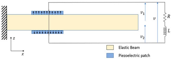
Figure 1.
Schematic presentation of the smart beam.
Coupled Electromechanical System
The derivation of the theoretical model of the piezoelectric beam structure follows the methodology outlined in [15] and it is based on the generalized Hamilton’s principle, given by
where denotes the kinetic energy, denotes the mechanical potential energy, denotes the electrical potential energy and denotes the virtual work done by the external forces. The definition of each term is given as
In the aforementioned formulae, represents the vector of mechanical displacements, and are the strain and stress tensor, respectively. Additionally, , and denote the electric field, the electric displacement, the force on the beam, and the electric charge, respectively. The symbol represents the mass density, denotes the electric potential, and signifies the volume under consideration. The superscripts and specifically refer to the beam structure and the piezoelectric layers, respectively. Following the assumptions of the Timoshenko beam theory, the components of displacement can be expressed as.
where , and are the total displacements along the coordinate directions, denotes time, , represent the axial and transverse displacements of the middle line of the beam, respectively, and is the rotation of the beam cross-section about the positive -axis. Assuming small deformations, the strain is related to the deformation through the following relations:
The linear constitutive equations of the piezoelectric layers can be expressed in terms of the 3-1 mode of piezoelectric constant operation and the 3-3 effect of piezoelectric permittivity as
where and represent the normal and shear stress, respectively, while and correspond to the normal and shear strain, respectively. Moreover, signifies the transverse electric displacement and and stand for the reduced stiffness coefficients. Additionally, denotes the piezoelectric constant and represents the electric permittivity constant. Finally, is the shear correction coefficient which is taken equal to The constitutive equations governing the behavior of elastic beams can be derived by setting their piezoelectric constants and to zero.
For a thin piezoelectric layer that is polarized in the thickness direction, the dominant component of the electric field can be expressed as
where is the electric potential difference between the electrodes covering the piezoelectric layer’s surface and denotes the thickness of the piezoelectric layer.
In this study, the beam has been discretized using two-node super-convergent elements with one electrical degree of freedom per piezoelectric layer and three mechanical degrees of freedom (DoF) per node. Discretizing the generalized displacement vector is given,
where are the super convergence shape functions [15].
Substituting Equations (7)–(12) into the energy expressions for Hamilton’s Principle and using standard finite element procedure, the following coupled electromechanical equations can be obtained:
In the Equations (12)–(14), the symbol represents the vector of the mechanical degrees of freedom (DoF), stands for the mass matrix of the system, stands for the stiffness matrix, corresponds to the mechanical force terms, denotes the electromechanical coupling matrix, and the piezoelectric capacitance, identical for both piezoelectric sheets. The elements of these matrices are not shown here for conciseness. Readers who are interested in more details about the FE formulations can consult to Ref. [15].
In the case where both piezoelectric layers are short-circuited, the difference of the electric potentials between their electrodes vanish (). Therefore, Equation (13) becomes
The components of the two piezoelectric patches are represented by the matrices and .
Since we are interested in vibration control, a powerful representation of the system in state space form will be developed, which contains both frequency and actuation responses of different shunt configurations and electrical components. The short-circuit Equation (15) is therefore converted into a state space form as shown below.
where
The matrices and depend on the choice of the observed inputs, which are given as
where all the elements of the matrix are zero except for the element.
In the case where an circuit is connected to the piezoelectric patches (Figure 1), the global output charge q is equal to each output charge generated by each piezoelectric layer, , whereas the global output voltage is the sum of the individual output voltages, that is, . Summing up Equations (13) and (14), we obtain
Applying Kirchhoff’s voltage law, the second-order equation for the electrical dynamics reads
Solving Equations (13) and (14) for and , respectively, substituting into (12) and using (20) and (21), we get the final electromechanical system equations:
where
Using the state vector the following state space form is obtained
where the state matrices and the input vector are given by
and
The output can be defined by
The matrices and depend on the choice of the outputs. For the present analysis, the output of interest is the tip displacement and the matrices, and are written as
where all the elements of the matrix are zero except for the element.
In order to derive the frequency response of the system, we must transform the state space model (26), (29) to transfer function representation. Taking the Laplace Transform of (26) and (29) (with zero initial conditions) and performing some trivial mathematical manipulations, the transfer function between the output and the input of the system is given by
The frequency response of a system is widely recognized as a function that establishes the relationship between the output response and a sinusoidal input of frequency . Specifically, the system’s frequency response at a given frequency can be obtained by substituting into its transfer function. It should be noted that the elements within the matrix represent the frequency response of the system for the -th degree of freedom when subjected to a force at the-th degree of freedom, at specific forcing frequency .
2.2. Piezoelectric Shunted Systems
A shunted piezoelectric circuit contains a piezoelectric transducer that is connected to an electric impedance, equivalent to a resistance, an inductance, a capacitance, or a suitable combination of them [43] and it is typical to connect on intelligent structures like beams. Resonant shunts can provide satisfactory solutions for single-mode control problems since they are adjusted to a reference natural frequency. They are effective, but additionally, they have certain drawbacks. For instance, very high inductance values might be required, particularly at low frequencies. Furthermore, multiple modes are difficult to control simultaneously via resonant shunts [41].
Several additional vibration control strategies, similar to tuned mass dampers, have features with some shunt circuit types in terms of their dynamic behavior [28]. Besides what is found with a tuned mass damper, electric resonance improves energy transfer while tuned to the mechanical mode under control. As a way to demonstrate the resonant piezoelectric shunt, a spring-mass system is used as a structural model [42]. The description of single degree of freedom mass-spring system has been derived from [41,42].
Simple mechanical systems and similar electric-powered circuits are used to model a control system according to resonant shunt piezoelectric circuits. To establish the coupled model, consider a shunted piezoelectric element connected in parallel with a spring of stiffness (a single DOF mass-spring system). This element represents the stiffness of the entire structure when the piezoelectric transducer is short-circuited, as is shown in Figure 2a. The electromechanical coupled system is derived from
where is the voltage between the material’s electrodes, is the longitudinal force within the piezoelectric material, and is the displacement of the electric charge. The global piezoelectric coefficient, , is given in or , while is the capacitance of piezoelectric element, which is measured when the mechanical system is not displaced ().
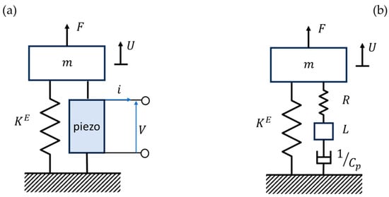
Figure 2.
The system with one mechanical degree of freedom using a shunt circuit is proven in (a); the mechanical system is in comparison to a piezoelectric shunt in (b).
Assuming m is the total mass of the system and is the external force applied to it, as in Figure 2a, Newton’s second law equation states that , which can be obtained by inserting from Equation (31).
While the electrodes of the piezoelectric elements are coupled, the eigenfrequency of the short circuit is determined as, . The last step is to substitute Equation (21) into Equation (32) which leads to:
Equation (33) takes into consideration the electric parameters and ; on the other hand, it is most effectively applied to systems with one mechanical DOF.
Figure 2b depicts an analogy between the electric shunt piezoelectric circuit and the mechanical system. The introduced equivalent mass and damper constitute the inductance and resistance of the shunt circuit. The capacitance of the piezoelectric element is equal to an additional equivalent spring with a constant equal to .
2.3. Optimization of the Shunt System
The selection of the appropriate resistance and inductance allows for the optimum attenuation performance of the dynamic system. Various methods of determining optimal values for inductance and resistance have been suggested for one degree of freedom system, such as [44,45,46].
The coupling factor is calculated as . Also, the resonant shunt angular frequency is given by , is the natural angular frequency in open circuit. The stiffness of the structure when the shunt system is open-circuited is calculated as . The short circuit’s eigenfrequency , which is the natural angular frequency in a short circuit. The damping ratio is determined as . Thus, the coupling factor can be defined from the open- and short-circuit natural frequencies as:
The resonant shunt is optimized by employing the approach defined by way of [45]. This approach is in fact a min-max optimization of the mass’s displacement parameter . For an activated , the maximum of the transfer function must be minimized.
The tuning of the resonant shunt consists in determining the values of and that minimize the maximum of Analytic calculations presented in [45] which are referred to maximum of around the vicinity of critical and gives
In the end, Equation (36) leads to the optimal inductance and resistance:
It should be noted that the previously described one-dimensional model is a rough simplification real-world systems and it is used herein for demonstration of the shunted piezoelectric concept, since vibrating pylons with considerable point masses at the top, lead to more complicated models of structural dynamics [47]. Nevertheless, the numerical example is based on a frequency-domain simplified finite element model. This can be helpful, provided that a geometric model of the pylon is used. In fact, the system under consideration is referred to as a multi-degree of freedom system according to [15,48] which has presented in the previous subsection and after that the optimization problem of our study will be described in detail.
Optimization Problem of the Present Study
The main goal of this work is to find the optimal values of the shunt circuit parameters to enhance attenuation at a single mechanical mode of the piezoelectric beam using the particle swarm optimization technique. This optimization procedure is performed by minimizing the maximum amplitude of frequency response function over the frequency band of interest:
where denotes the vector of design variable and is the tip response of the beam for an excitation at the same point.
Based on the above considerations, the optimization problem is formulated as follows:
Find the optimal vector of design variable to
where denote the lower bounds of the design variables and denote the upper bounds of the design variables. In order to determine the optimal values of the design variables, the optimization problem is addressed through the application of the particle swarm optimization technique. A MATLAB 2021a algorithm has been created to execute the FE model as well as the optimization problem stated above. Particularly, the optimization process is simulated within the Matlab environment by utilizing the particle swarm function.
2.4. Applications of the Technology
Recent research in passive shunted piezoelectric systems has highlighted their diverse applications in engineering domains such as vibration damping, energy harvesting, structural health monitoring, and acoustic noise reduction. These are summarized in Figure 3. In vibration damping, passive shunt circuits integrated with piezoelectric materials offer an effective means to attenuate unwanted vibrations in mechanical structures. By dissipating mechanical energy through impedance, these systems enhance structural stability and performance, mitigating the risk of fatigue and failure. For instance, in the study of Pernod et al. [49], a resonant piezoelectric shunt system is used for passive vibration mitigation of a marine lifting surface under hydrodynamic flows.
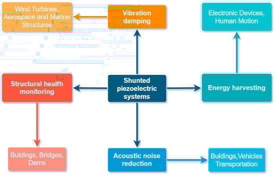
Figure 3.
The most popular applications of shunted piezoelectric systems.
Moreover, passive shunted piezoelectric systems have emerged as promising solutions for energy harvesting, converting ambient mechanical vibrations into electrical energy for powering various devices and sensors. Through optimized shunt tuning techniques, these systems maximize energy conversion efficiency, enabling sustainable and autonomous operation in remote or inaccessible environments. Additionally, in structural health monitoring, passive shunted piezoelectric systems facilitate real-time detection and assessment of structural damage, ensuring timely maintenance and enhancing safety. Lastly, in acoustic noise reduction applications, these systems generate anti-noise signals to cancel out unwanted noise, improving acoustic comfort and reducing environmental impact. An example is described in [50], where a shunted piezoelectric system is implemented for the reduction of the squeal noise level in railway wheels. Through their multifaceted capabilities, passive shunted piezoelectric systems continue to advance engineering solutions across diverse fields, addressing critical challenges and driving innovation forward.
3. Shunted Piezoelectric Systems for Vibration Attenuation of Large Structures
A simplified cantilever beam model of an onshore wind turbine tower has been used in this paper. This model is based on a flexible, continuous beam which constitutes a good approach to a real turbine tower in the frequency domain. The steel host beam has a single PIC151 piezoceramic, which is located 1.82 m horizontally and 1.14 m vertically from the fixed end [39]. The geometrical characteristics of the structure and the material of the beam are derived from [39]. The piezo characteristics have been taken from [51] and both of them are presented in the Table 1. The electrodes are connected in series to a passive electrical circuit composed of a resistor and an inductor , thus constituting a resonant shunt [52]. These shunt dampers are intended to mitigate the vibrations of the turbine tower.

Table 1.
The material of the beam and the geometric properties of the structure are taken from [39].
The self-weight of the tower itself is 1422 kN, according to [53]. The behavior of the tower for seismic loading is equivalent to a concentrated force at the tip. The load value is equal to 20% of the tower weight and is depicted in the Figure 4. The calculation follows as Ft = 1422 kN * 20% = 284.4 kN.
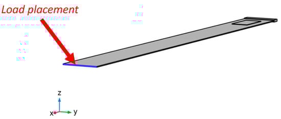
Figure 4.
The position of the force on the model.
A cantilever beam is considered with the following mechanical boundary conditions: fixed support at one end and free at the other, where a harmonic load is applied. The 1-D in-house application uses a finite element method according to the super-convergent FE approach pioneered by Foutsitzi et al. [54]. There are 41 one-dimensional beam elements in the mesh, which provide information on the mesh element quality of the reduced-order 1-D model. Similarly, 810 hexahedric components make up the Multiphysics 3-D model’s mesh.
4. Numerical Results
This section is divided into five parts. The results of the model of the previous section are examined as the first case study. Furthermore, a second case study is considered, in which piezoelectric patches are placed in a metamaterial-like periodic pattern. More specifically, the four initial parts are obtained from simulations experiments in COMSOL Multiphysics Environment. At first, an eigenfrequency analysis is implemented, which provides the first four bending modes in open and short circuit conditions. Next, the frequency response graph of the dynamic response of the structure is obtained by utilizing models from two different software to compare the results. After that, the second case study is investigated. A feasibility and an economic study about the implementation of this technology is carried out. Finally, the presented passive control method is compared to the active control method, which is presented in [39].
4.1. Eigenfrequency Analysis—1st Case Study
The frequencies for the first four bending modes of the beam are given in Table 2 and are derived using the Multiphysics 3-D finite element model [40].
Table 2.
Natural frequencies (Hz) from finite element computation (FE).
Furthermore, the finite element model of the structure is depicted in Figure 5a. Figure 5b presents the first eigenmode in open circuit and Figure 5c shows the first shorted eigenmode.
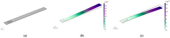
Figure 5.
FEM model and first natural modes of the structure. (a) finite-element mesh (b) open-circuit first bending mode 0.034822 Hz (c) short-circuit first bending mode 0.034631 Hz.
4.2. Dynamic Response of Two Finite Element Models and Comparison—1st Case Study
The goal in the present section is the reduction of the tip displacement. Here, the second mode is the only one mentioned since it has more authority than other structural modes because of the piezoelectric patch location. The Frequency Response Graph of the same electromechanical system has also been computed using a commercial finite element analysis package and compared with the results obtained by the in-house 1-D finite element method in MATLAB. An optimization technique, namely the particle swarm algorithm, is used to optimize the shunt attenuation parameters for the in-house 1D finite element model [15]. These values are used as presented in Table 3 and a parametric study is performed for the 3-D Multiphysics model to take the most suitable electrical circuit values.
Table 3.
Shunt element values based on a 1-D and a 3-D FE model.
The impact of damping for both models around the second eigenfrequency is shown in Figure 6. A similar damping performance is shown when comparing the output of the commercial FE model with the in-house FE model.
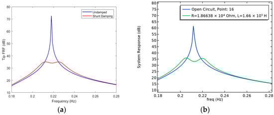
Figure 6.
Simulated frequency response of the two models. (a) Open Circuit (blue line) and Shunt Circuit (red line), MATLAB 1-D Environment (b) Open Circuit (blue line) and Shunt Circuit (green line), Comsol 3-D Environment.
4.3. Investigation of Metamaterials—2nd Case Study
The above results demonstrate the considerably large size of piezoelectric transducers as well as the required values of electric parameters of the circuit, leading to hardly feasible application for real-world systems. Under this consideration, the modeling of piezoelectric patches as a metamaterial with periodic patterns is conceptualized. Figure 7a illustrates the proposed modified smart structure. The initial dimensions of the piezo came from Table 1. Then, the patch is separated into five equivalent parts which comprise the metamaterial periodic pattern. The distance between each piezo is equal to 0.5 m. The corresponding five sub-circuits are coupled with the new metamaterial, as shown in Figure 7b. This modification provides better results in comparison to the previous section, also proving the applicability of metamaterial approaches to tackle the infeasibility issues discussed in the previous subsection.
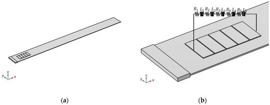
Figure 7.
(a) The model under study. (b) Metamaterial periodic pattern connected with the electrical circuit.
In Figure 8, results corresponding to Section 4.2. (1st case study) and Section 4.3. (2nd case study) are compared. Despite that, the simulated Frequency Response is similar; as was expected, the novelty can be found in the design of metamaterial and the values of electrical parameters. The prices of electrical components are reduced, and they are equal to 1/5 of the initial. The dimensions of piezo are easier to manufacture and as an overall conclusion, this modification is a cost-effective solution.
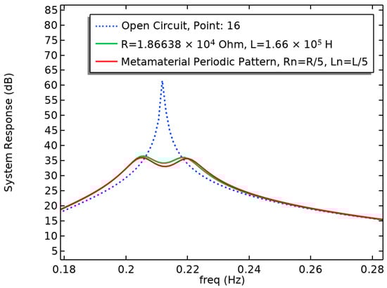
Figure 8.
The model’s simulated frequency response. Open Circuit (blue-dashed line), Shunt Circuit—1st case study (green line) and Shunt Circuit—2nd case study (red line), Comsol 3-D Environment.
The current flow from an amperometer connected in series with the last resistance and inductor is shown in Figure 9. The measurement was conducted at 10 s and a sinusoidal signal is observed that repeats periodically.
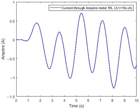
Figure 9.
Current flow via an amperometer.
4.4. Feasibility and Economic Analysis
First of all, the aforementioned findings indicate the large size of piezoelectric transducers, as well as the infeasible circuit’s electric properties. One additional finding is that the large structure produces low-frequency vibrations. For the given numerical values, piezoelectric elements of similar dimensions and passive inductor values are not currently available in the market. However, there are alternatives like the parallel placement of piezoelectrics (known as a mosaic) and the series placement of passive inductors. It can be found in applications like the one shown in the reference [55]. In the work of Sénéchal [55], the vibration reduction of a turbojet fan blade with piezoelectric patches is studied, connected to a passive electrical circuit, whereas the piezo patches’ positions and dimensions are optimized for finding the best design. A practical implementation in [56] has been published and it can be considered in future research efforts.
Furthermore, piezoelectric materials can be ordered by the piece. Each company gives them different codes and they have other specifications. Generally, they are cheap, and the price depends on the dimensions and application. Large values of circuit components are possible, but they are not cost-effective. Typically, a passive inductor cannot be manufactured but can be replaced for example with a semi-passive synthetic inductor (i.e., Synthetic Inductor Antoniou [55]) or like in [42]. A PSD System is easy to install and does not require a power source.
4.5. Performance of the Two Vibration Control Methods
For comparison reasons, a piezoelectric shunt damper (PSD) and a Positive Position Feedback (PPF) controller are tuned using a simplified model of an onshore wind turbine tower. The first belongs to a passive damping method and the other to an active one. Table 4 shows that PSD presents better efficiency than PPF with 47.62% of second mode reduction. One possible reason is that the PPF controller requires a power source, while PSD does not need external energy.
Table 4.
Efficiency comparison of passive and active vibration control method.
5. Experiment of a Micro-Scale Shunted Piezoelectric System
An experimental verification of the used concept is presented by following similar works published in the literature, see, e.g., [48,57]. This experimental study introduces a setup featuring a steel beam excited through a coil and integrated with piezoelectric strategically positioned to convert mechanical energy into electrical energy and vice versa. Two piezo transducers are made from the piezoelectric material PIC255. These piezoelectric actuators have wrapped electrodes and are installed on the beam with opposite polarization directions. They are both placed with their electrodes as close as possible to the clamped end of the beam. The experimental setup is illustrated in Figure 10. The core of this experiment lies in the application of a shunted circuit comprising a resistor and inductances, carefully tuned to dampen oscillations at the second natural frequency. According to the literature, they are called resonant shunt circuits [41,42,46,49].
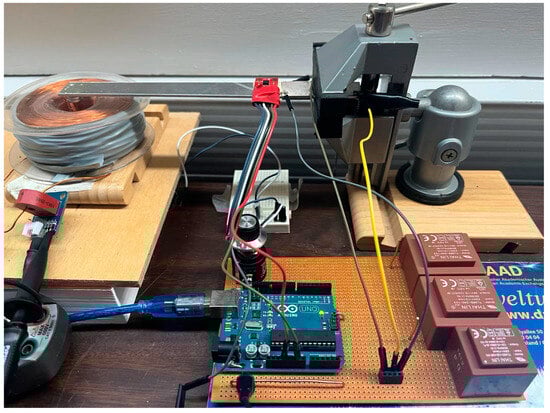
Figure 10.
Experimental set-up of the cantilever beam with piezoelectric patches, electric circuit, accelerometer, and coil.
The experimental procedure requires the generation and amplification of frequency and power signals, which are then applied to excite the steel beam through the coil. Vertical displacement measurements, measured by an accelerometer, provide crucial feedback on the efficiency of the passive damping technique. Concurrently, the generator (Figure 11a) receives the signal source and generates high accuracy and high stability waveforms that are based on stored digital data that describes the constantly changing voltage levels of an AC signal. The oscilloscope (Figure 11b) monitors sensor signals, enabling the observation of resonance frequencies and the quantification of the reduction in oscillations achieved through the shunted circuit technology.
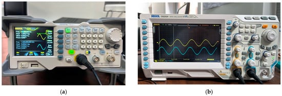
Figure 11.
Equipment for experiment. (a) Waveform Generator (b) Digital Oscilloscope.
From the obtained measurements, the open and short circuit frequencies around the second mode are calculated. Using Equation (37), the most suitable values for resistance and inductance can be calculated, which are presented in the Table 5. The calculations and the methodology follow the work of Thomas et al. 2009 [51].
Table 5.
Piezoelectric capacitance, eigenfrequencies, piezoelectric coupling factor and electric circuit values.
Oscillation amplitudes are measured before and after the piezoelectric shunt control for vibration damping of the second eigenmode. They are shown in Figure 12. The measured electrical quantity is related to the difference between the maximum value and the minimum value of the waveform. Thus, the percentage of amplitude reduction is equal to 24.4%.
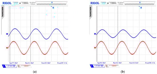
Figure 12.
System Response. (a) Open circuit terms, blue curve. (b) Shunt circuit terms, blue curve.
Results from the experiment underpin the effectiveness of the passive damping approach, showcasing a significant reduction in oscillation magnitude, particularly at the targeted second eigenmode frequency. This study underlines the potential of passive damping techniques, offering a cost-effective and energy-efficient solution for vibration control in engineering applications. Further exploration into real-world implementations holds promise for advancing the practical utility of this passive damping method.
Validation of Computational Models
A 1-D FE model in MATLAB 2021a and a 2-D FE model in commercial finite element software (COMSOL 6.0), having the same structural and electrical characteristics as the micro-scale experimental model, are developed [48]. For finding the optimal electrical circuit values in a MATLAB environment, the particle swarm algorithm has been used. Similarly, a parametric analysis in COMSOL has been conducted to find the appropriate electrical circuit values. The electrical circuit values for each model are shown in Table 6.
Table 6.
Shunt element values based on a 1-D and a 2-D FE model.
The frequency response of each model is investigated, and the results are compared. Figure 13 shows the verification of the two models. Therefore, this comparison has a good agreement, and the correctness of the models is validated.
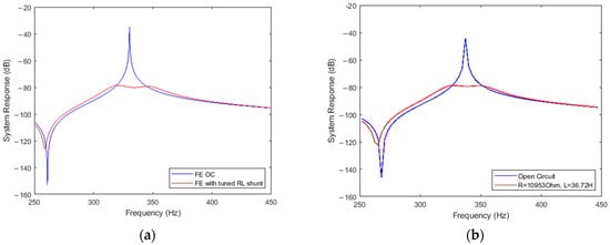
Figure 13.
Simulated frequency response of the two models. Steel beam, Piezo. PIC255 and Appropriate RL circuit values. (a) Open Circuit (blue line) and Shunt Circuit (red line), MATLAB 1-D Environment (b) Open Circuit (blue line) and Shunt Circuit (red line), Comsol 2-D Environment.
6. Conclusions
Analyses of the utility of piezoelectric shunted systems to reduce wind turbine vibrations were performed in this paper. The primary contribution of this work is that shunted piezoelectric technology can be used for massive structures and might yield extremely good outcomes. This analysis proves that the usage of piezoelectric shunted circuits leads to damping in the eigenfrequency region. A finite element software has been used to create a simplified model of the turbine’s pylon using connected shunted piezoelectric circuits. In order to verify the effectiveness of the suggested vibration suppression approach and to consider its feasibility, a parametric analysis has been performed.
Furthermore, the effectiveness of metamaterial-like periodic patterns is studied. These findings show significant reductions in both the size of transducers and the values of electrical components, leading to cost-effective solutions with simplified circuits. This innovative approach is in accordance with modern developments in smart structures.
Before real life implementation, a number of future research steps can be proposed. First, experimental validation and FE models on the wind turbine tower itself with all the necessary details of the structure can be proposed. Concurrent optimization for the piezoelectric patches (position, materials) and the circuit electric parameters may lead to innovative results. Feedback from industry and hardware producers will eventually lead to effective and economically feasible results.
Author Contributions
Conceptualization, P.A. and M.-S.D.; methodology, M.-S.D., K.M. and G.A.F.; software, G.A.F. and M.-S.D.; validation, M.-S.D. and G.A.F.; formal analysis, M.-S.D.; investigation, M.-S.D.; resources, M.-S.D., K.M. and G.A.F.; data curation, M.-S.D.; writing—original draft preparation, M.-S.D. and G.A.F.; experimental work, M.-S.D. and K.M.; writing—review and editing, G.A.F., P.A. and G.E.S.; visualization, M.-S.D.; supervision, G.A.F., P.A. and G.E.S.; project administration, G.E.S. All authors have read and agreed to the published version of the manuscript.
Funding
This research received no external funding.
Data Availability Statement
Models can be provided after reasonable request.
Acknowledgments
The authors would like to acknowledge helpful discussions and support from the members of the COST Action 20109 MODENERLANDS.
Conflicts of Interest
The authors declare no conflicts of interest.
References
- Qiao, Y.; Han, S.; Deng, Y.; Liu, Y.; Dong, J.; Pan, L.; Li, R.; Zhao, B. Research on variable pitch control strategy of wind turbine for tower vibration reduction. J. Eng. 2017, 2017, 2005–2008. [Google Scholar] [CrossRef]
- Karpenko, M.; Stosiak, M.; Deptuła, A.; Urbanowicz, K.; Nugaras, J.; Krolczyk, G.; Żak, K. Performance evaluation of extruded polystyrene foam for aerospace engineering applications using frequency analyses. Int. J. Adv. Manuf. Technol. 2023, 126, 5515–5526. [Google Scholar] [CrossRef]
- Karpenko, M.; Skačkauskas, P.; Prentkovskis, O. Methodology for the Composite Tire Numerical Simulation Based on the Frequency Response Analysis. Eksploat. Niezawodn.—Maint. Reliab. 2023, 25, 163289. [Google Scholar] [CrossRef]
- Malliotakis, G.; Alevras, P.; Baniotopoulos, C. Recent Advances in Vibration Control Methods for Wind Turbine Towers. Energies 2021, 14, 7536. [Google Scholar] [CrossRef]
- Machado, M.R.; Dutkiewicz, M. Wind turbine vibration management: An integrated analysis of existing solutions, products, and Open-source developments. Energy Rep. 2024, 11, 3756–3791. [Google Scholar] [CrossRef]
- Chatziathanasiou, G.M.; Chrysochoidis, N.A.; Saravanos, D.A. A semi-active shunted piezoelectric tuned mass damper for robust vibration control. J. Vib. Control 2021, 28, 2969–2983. [Google Scholar] [CrossRef]
- Zhou, F.; Yang, J.; Pang, J.; Wang, B. Research on control methods and technology for reduction of large-scale wind turbine blade vibration. Energy Rep. 2023, 9, 912–923. [Google Scholar] [CrossRef]
- Liu, H.; Yang, S.; Tian, W.; Zhao, M.; Yuan, X.; Xu, B. Vibration Reduction Strategy for Offshore Wind Turbines. Appl. Sci. 2020, 10, 6091. [Google Scholar] [CrossRef]
- Kapasakalis, K.A.; Gkikakis, A.E.; Sapountzakis, E.J.; Chatzi, E.N.; Kampitsis, A.E. Multi-objective optimization of a negative stiffness vibration control system for offshore wind turbines. Ocean Eng. 2024, 303, 117631. [Google Scholar] [CrossRef]
- Elias, S. Vibration improvement of offshore wind turbines under multiple hazards. Structures 2024, 59, 105800. [Google Scholar] [CrossRef]
- Das, A.; Ding, H. Compliant liquid dampers-inerter for mitigating wind-, wave-, and earthquake-induced vibrations of monopile offshore wind turbines. Ocean Eng. 2024, 301, 117486. [Google Scholar] [CrossRef]
- Li, J.-Y.; Zhu, S.; Zhang, J.; Ma, R.; Zuo, H. Vibration control of offshore wind turbines with a novel energy-adaptive self-powered active mass damper. Eng. Struct. 2024, 302, 117450. [Google Scholar] [CrossRef]
- Patro, S.R.; Panda, S.; Ramana, G.V.; Banerjee, A. Optimal multiple tuned mass dampers for monopile supported offshore wind turbines using Genetic Algorithm. Ocean Eng. 2024, 298, 117356. [Google Scholar] [CrossRef]
- Liu, Y.; Li, X.; Shi, W.; Wang, W.; Jiang, Z. Vibration control of a monopile offshore wind turbines under recorded seismic waves. Renew. Energy 2024, 226, 120455. [Google Scholar] [CrossRef]
- Marakakis, K.; Tairidis, G.K.; Foutsitzi, G.A.; Antoniadis, N.A.; Stavroulakis, G.E. New Optimal Design of Multimode Shunt-Damping Circuits for Enhanced Vibration Control. Signals 2022, 3, 830–856. [Google Scholar] [CrossRef]
- Neubauer, M.; Wallaschek, J. Vibration damping with shunted piezoceramics: Fundamentals and technical applications. Mech. Syst. Signal Process. 2013, 36, 36–52. [Google Scholar] [CrossRef]
- Pohl, M.; Rose, M. Piezoelectric shunt damping of a circular saw blade with autonomous power supply for noise and vibration reduction. J. Sound Vib. 2016, 361, 20–31. [Google Scholar] [CrossRef]
- Gripp, J.A.B.; Rade, D.A. Vibration and noise control using shunted piezoelectric transducers: A review. Mech. Syst. Signal Process. 2018, 112, 359–383. [Google Scholar] [CrossRef]
- da Silva, M.M.; Venter, G.S.; Varoto, P.S.; Coelho, R.T. Experimental results on chatter reduction in turning through embedded piezoelectric material and passive shunt circuits. Mechatronics 2015, 29, 78–85. [Google Scholar] [CrossRef]
- Biglari, H.; Fakhari, V. Edgewise vibration reduction of small size wind turbine blades using shunt damping. J. Vib. Control 2020, 26, 186–199. [Google Scholar] [CrossRef]
- Awada, A.; Younes, R.; Ilinca, A. Review of Vibration Control Methods for Wind Turbines. Energies 2021, 14, 3058. [Google Scholar] [CrossRef]
- Livet, S.; Collet, M.; Berthillier, M.; Jean, P.; Cote, J.M. Turbomachinery blades damping thanks to optimized shunted piezoelectric circuits. In Proceedings of the 15th International Symposium on: Smart Structures and Materials & Nondestructive Evaluation and Health Monitoring, San Diego, CA, USA; 2008; p. 692812. [Google Scholar]
- Abdullah, Y.; Baz, A. Brake Squeal: A Control Strategy Using Shunted Piezoelectric Pads. J. Vib. Acoust. 2021, 143, 031005. [Google Scholar] [CrossRef]
- Morad, A.M.; Kamel, M.; Khalil, M.K. Vibration damping of aircraft propeller blades using shunted piezoelectric transducers. IOP Conf. Ser. Mater. Sci. Eng. 2021, 1172, 012007. [Google Scholar] [CrossRef]
- Aabid, A.; Parveez, B.; Raheman, M.A.; Ibrahim, Y.E.; Anjum, A.; Hrairi, M.; Parveen, N.; Mohammed Zayan, J. A Review of Piezoelectric Material-Based Structural Control and Health Monitoring Techniques for Engineering Structures: Challenges and Opportunities. Actuators 2021, 10, 101. [Google Scholar] [CrossRef]
- Munoa, J.; Beudaert, X.; Dombovari, Z.; Altintas, Y.; Budak, E.; Brecher, C.; Stepan, G. Chatter suppression techniques in metal cutting. CIRP Ann. 2016, 65, 785–808. [Google Scholar] [CrossRef]
- Preumont, A. Vibration Control of Active Structures; Springer: Berlin/Heidelberg, Germany; New York, NY, USA, 2018; ISBN 978-3-319-72295-5. [Google Scholar]
- Marakakis, K.; Tairidis, G.K.; Koutsianitis, P.; Stavroulakis, G.E. Shunt Piezoelectric Systems for Noise and Vibration Control: A Review. Front. Built Environ. 2019, 5, 64. [Google Scholar] [CrossRef]
- Koutsianitis, P.I.; Tairidis, G.K.; Drosopoulos, G.A.; Stavroulakis, G.E. Conventional and star-shaped auxetic materials for the creation of band gaps. Arch. Appl. Mech. 2019, 89, 2545–2562. [Google Scholar] [CrossRef]
- Lu, Z.; Zhao, S.; Ma, C.; Dai, K. Experimental and analytical study on the performance of wind turbine tower attached with particle tuned mass damper. Eng. Struct. 2023, 294, 116784. [Google Scholar] [CrossRef]
- Tang, J.; Dai, K.; Luo, Y.; Bezabeh, M.A.; Ding, Z. Integrated control strategy for the vibration mitigation of wind turbines based on pitch angle control and TMDI systems. Eng. Struct. 2024, 303, 117529. [Google Scholar] [CrossRef]
- Tateo, F.; Collet, M.; Ouisse, M.; Cunefare, K. Design variables for optimizing adaptive metacomposite made of shunted piezoelectric patches distribution. J. Vib. Control 2016, 22, 1838–1854. [Google Scholar] [CrossRef]
- Zhou, W.; Muhammad; Chen, W.; Chen, Z.; Lim, C.W. Actively controllable flexural wave band gaps in beam-type acoustic metamaterials with shunted piezoelectric patches. Eur. J. Mech.—ASolids 2019, 77, 103807. [Google Scholar] [CrossRef]
- Li, J.; Miao, Z.; Ma, Q.; Lin, W. Size-dependent complex band structure of tunable beam metamaterial with shunted piezoelectric array. Acta Mech. 2022, 233, 889–904. [Google Scholar] [CrossRef]
- Chen, S. Wave propagation in acoustic metamaterials with resonantly shunted cross-shape piezos. J. Intell. Mater. Syst. Struct. 2018, 29, 2744–2753. [Google Scholar] [CrossRef]
- Ji, G.; Huber, J. Recent progress in acoustic metamaterials and active piezoelectric acoustic metamaterials—A review. Appl. Mater. Today 2022, 26, 101260. [Google Scholar] [CrossRef]
- Giorgio, I.; Galantucci, L.; Della Corte, A.; Del Vescovo, D. Piezo-electromechanical smart materials with distributed arrays of piezoelectric transducers: Current and upcoming applications. Int. J. Appl. Electromagn. Mech. 2015, 47, 1051–1084. [Google Scholar] [CrossRef]
- Dalela, S.; Balaji, P.S.; Jena, D.P. A review on application of mechanical metamaterials for vibration control. Mech. Adv. Mater. Struct. 2022, 29, 3237–3262. [Google Scholar] [CrossRef]
- López-Romero, M.Á.; Santos Peñas, M. A Positive Position Feedback controller for vibration control of wind turbines. Energy Rep. 2023, 9, 1342–1353. [Google Scholar] [CrossRef]
- Daraki, M.-S.; Marakakis, K.; Alevras, P.; Foutsitzi, G.A.; Stavroulakis, G.E. Passive Shunted Piezoelectric Systems for Vibration Control of Wind Turbine Towers—A feasibility study. In Book of Abstracts, Proceedings of the COST Action CA20109 MODENERLANDS. Strategic Workshop “Energy Islands. Technical Challenges and Industrial Opportunities”, Esch-sur-Alzette, Luxembourg, 15–16 May 2023; Rebelo, C., Baniotopoulos, C., Hemida, H., Marino, E., Borg, R.P., Glumac, A., Eds.; COST: Brussels, Belgium, 2023; pp. 77–78. Available online: https://modenerlands.eu/wp-content/uploads/2023/07/CA20109_SWLuxembourg.pdf (accessed on 13 May 2024).
- Tairidis, G.K. Vibration control of smart composite structures using shunted piezoelectric systems and neuro-fuzzy techniques. J. Vib. Control 2019, 25, 2397–2408. [Google Scholar] [CrossRef]
- Lossouarn, B.; Aucejo, M.; Deü, J.-F.; Multon, B. Design of inductors with high inductance values for resonant piezoelectric damping. Sens. Actuators Phys. 2017, 259, 68–76. [Google Scholar] [CrossRef]
- Reza Moheimani, S.O.; Fleming, A.J. Piezoelectric Transducers for Vibration Control and Damping; Advances in Industrial Control; Springer: London, UK, 2006; ISBN 978-1-84628-331-4. [Google Scholar]
- Hagood, N.W.; Von Flotow, A. Damping of structural vibrations with piezoelectric materials and passive electrical networks. J. Sound Vib. 1991, 146, 243–268. [Google Scholar] [CrossRef]
- Thomas, O.; Ducarne, J.; Deü, J.-F. Performance of piezoelectric shunts for vibration reduction. Smart Mater. Struct. 2012, 21, 015008. [Google Scholar] [CrossRef]
- Soltani, P.; Kerschen, G.; Tondreau, G.; Deraemaeker, A. Piezoelectric vibration damping using resonant shunt circuits: An exact solution. Smart Mater. Struct. 2014, 23, 125014. [Google Scholar] [CrossRef]
- Dadoulis, G.I.; Manolis, G.D. A note on analytical solutions for vibrations of beams with an attached large mass. Arch. Appl. Mech. 2022, 92, 1973–1982. [Google Scholar] [CrossRef]
- Marakakis, K. Simulation and optimization of smart structures. PhD Dissertation, Technical University of Crete, Chania, Greece, 2022. [Google Scholar]
- Pernod, L.; Lossouarn, B.; Astolfi, J.-A.; Deü, J.-F. Vibration damping of marine lifting surfaces with resonant piezoelectric shunts. J. Sound Vib. 2021, 496, 115921. [Google Scholar] [CrossRef]
- Marjani, S.R.; Younesian, D. Performance Analysis of Piezoelectric Actuators in Railway Wheel Squealing Noise Mitigation. Shock Vib. 2019, 2019, 1232350. [Google Scholar] [CrossRef]
- Thomas, O.; Deü, J.-F.; Ducarne, J. Vibrations of an elastic structure with shunted piezoelectric patches: Efficient finite element formulation and electromechanical coupling coefficients. Int. J. Numer. Methods Eng. 2009, 80, 235–268. [Google Scholar] [CrossRef]
- Luo, Y.; Sun, H.; Wang, X.; Zuo, L.; Chen, N. Wind Induced Vibration Control and Energy Harvesting of Electromagnetic Resonant Shunt Tuned Mass-Damper-Inerter for Building Structures. Shock Vib. 2017, 2017, 4180134. [Google Scholar] [CrossRef]
- Baniotopoulos, C.; Lavassas, I.; Zervas, P.; Nikolaidis, G. Design of large scale wind turbine towers in seismic areas. In Behaviour of Steel Structures in Seismic Areas; CRC Press: London, UK, 2011; pp. 319–324. ISBN 978-0-429-21704-3. [Google Scholar]
- Foutsitzi, G.; Hadjigeorgiou, E.; Gogos, C.; Stavroulakis, G. Modal shape control of smart composite beams using piezoelectric actuators. In Proceedings of the 10th HSTAM International Congress on Mechanics, Chania, Greece, 25–27 May 2013. [Google Scholar]
- Sénéchal, A. Réduction de vibrations de structure complexe par shunts piézoélectriques: Application aux turbomachines. Ph.D. Thesis, Conservatoire National des Arts et Métiers, Paris, France, 2011. [Google Scholar]
- Sénéchal, A.; Thomas, O.; Deü, J.-F. Optimization of Shunted Piezoelectric Patches for Vibration Reduction of Complex Structures: Application to a Turbojet Fan Blade. In Proceedings of the Volume 5: 22nd International Conference on Design Theory and Methodology, Montreal, QC, Canada, 15–18 August 2010; Special Conference on Mechanical Vibration and Noise. ASMEDC: Montreal, QC, Canada, 2010; pp. 695–704. [Google Scholar]
- Deweert, R. Multimodal vibration damping with piezoelectric shunts. Master’s Dissertation, Ghent University, Gent, Belgian, 2019. [Google Scholar]
Disclaimer/Publisher’s Note: The statements, opinions and data contained in all publications are solely those of the individual author(s) and contributor(s) and not of MDPI and/or the editor(s). MDPI and/or the editor(s) disclaim responsibility for any injury to people or property resulting from any ideas, methods, instructions or products referred to in the content. |
© 2024 by the authors. Licensee MDPI, Basel, Switzerland. This article is an open access article distributed under the terms and conditions of the Creative Commons Attribution (CC BY) license (https://creativecommons.org/licenses/by/4.0/).