Abstract
This paper highlights the importance of accurately modeling the operational constraints of Combined-Cycle Gas Turbines (CCGTs) within a unit-commitment framework. In practice, in Colombia, when given an initial dispatch by the Independent System Operator, CCGT plants are operated according to the results of heuristic simulation codes. Such heuristics often omit technical operating constraints, including hot, warm, or cold startup ramps; the minimum operation hours required for a gas turbine to start a steam turbine; the relationship between the dispatched number of steam and gas turbines; the load distribution among gas turbines; and supplementary fires. Most unit-commitment models in the literature represent standard technical constraints like startup, shutdown, up/down ramps, and in some cases, supplementary fires. However, they typically overlook other real-life CCGT operating constraints, which were considered in this work. These constraints are crucial in integrated energy systems to avoid equipment damage, which can potentially put CCGT plants out of service and ultimately lead to lower operating costs.
1. Introduction
1.1. Motivation
In modern power systems, power plant operators and Independent System Operators (ISOs) rely on mathematical models to simulate various operating conditions for specific scenarios, ensuring power system security and reliability. These models are crucial, especially for Combined-Cycle Gas Turbine (CCGT) plants, which are prevalent worldwide due to their high efficiency and flexibility in integrating renewable energy resources [1,2,3]. Accurate representation of CCGTs’ operational elements is essential for simulating the correct power output available to the ISO for meeting demand and avoiding equipment damage [4,5,6].
The Colombian power system, with its diverse CCGT plants, exemplifies this need. The largest plant, TEBSA, located in northern Colombia with a 5 × 2 configuration (5 gas turbines and 2 steam turbines), plays a vital role in system reliability and security. Its actual power output depends on the thermal states of the gas turbines and their interaction with the steam turbines, which require specific temperature and pressure conditions to operate effectively.
Currently, most Colombian CCGT plants, including TEBSA, lack a mathematical optimization model for detailed operation planning based on dispatch. Moreover, the Colombian ISO lacks a faithful technical representation of these plants. This gap often leads to operational inefficiencies and technical issues, such as equipment failures or deviations from unit-commitment programs. For instance, TEBSA’s operations often assume a hot startup condition or overlook the minimum number of gas units needed for steam turbine operation, leading to preventable equipment issues [7] (see Figure 1). Addressing these challenges requires a comprehensive optimization model that accurately represents the complex operating conditions of CCGTs.
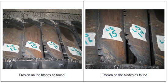
Figure 1.
Steam turbine equipment failures due to inadequate steam temperature and pressure conditions.
Therefore, this paper proposes a Self-Unit-Commitment (SEUC) model, formulated as a Mixed-Integer Programming (MIP) problem, to address these challenges and to accurately represent the detailed operating conditions of a CCGT plant given a specific dispatch. The model introduces two novel aspects: firstly, it considers the minimum operation hours required for a gas turbine to start a steam turbine, a factor not previously included in existing Unit-Commitment (UC) models to the best of our knowledge; secondly, it accounts for the load distribution among gas turbines. A crucial feature of our model is its treatment of the CCGT plant, representing gas and steam turbines separately, rather than as a single entity. This granular representation enables the ISO to execute a more-precise unit-commitment plan for these plants, ensuring better accuracy in active and reactive power output. Such accuracy is vital for supporting grid constraints and adhering to the operational rules of the CCGT, thereby reducing program deviations (Although reactive power output is not directly considered, the model’s active power outputs for each CCGT unit can be utilized in power system analysis software by the ISO, where the capability curve of each unit at different voltage levels is modeled). Furthermore, this model can be integrated into a broader UC framework for dispatching CCGT plants within a general power system.
1.2. Literature Review
Modeling approaches for Combined-Cycle Gas Turbines (CCGTs) in the literature vary significantly. One method involves representing CCGT components individually, focusing on the separate functionality of gas and steam turbines, as seen in studies like [8,9,10,11,12,13]. Another common approach models the entire CCGT plant using configurations or modes, as detailed in [2,14,15,16,17,18,19,20,21,22]. Our work adopted an individual component representation, but included constraints typical of CCGT configurations, such as power output limits, startup/shutdown ramps, and the number of gas and steam units. This approach is similar to that in [12], but our model uniquely combines both component and mode models.
CCGTs are often modeled using either configurations or individual representations of gas and steam turbines. Works like [2,14,18] propose a Mixed-Integer Programming (MIP) model for Unit Commitment (UC), considering CCGT operation modes and addressing ramping and minimum uptime/downtime constraints. They also consider startup/shutdown costs associated with mode transitions, improving computational performance. However, these models typically overlook operational constraints like the minimum operation hours required for a gas turbine to start a steam turbine and load distribution requirements.
Refs. [8,9] propose componentwise formulations for CCGTs, incorporating them into UC problems. These models address the interdependence of gas and steam turbines, with the steam turbine’s power output dependent on the gas turbine’s performance. Ref. [8] focuses on ramping constraints on a minute-by-minute basis, aligning with the hourly dispatch requirements of the Colombian energy market. However, this model does not consider crucial constraints like minimum startup hours, differentiation between hot and cold startups for steam turbines, and the load distribution among gas turbines, which are essential for maintaining operational integrity and preventing equipment failures.
Our work presents a hybrid model that captures the benefits of both component- and configuration-based approaches. Unlike [23], which proposes a similar hybrid model, our approach is tailored to the Colombian energy market framework, considering the specific operational constraints and bidding policies for CCGT units. We incorporated supplementary fires, an element also modeled in [8,23], which enhance the steam turbine’s power output without increasing the gas turbine’s output. This was achieved using the Heat Recovery Steam Generator (HRSG), with the assumption that steam quality is maintained when the operational constraints are met.
1.3. Contributions
The main contributions of this paper are as follows:
- The introduction of the SEUC model for CCGT hourly dispatch, accommodating individual the minimum uptime/downtime constraints for each gas and steam unit, ramp rates, and operational rules for steam turbines, including the requisite number of gas turbines for optimal steam production.
- The incorporation of steam turbine startup processes in the model, taking into account the thermal state of each unit (hot or cold) and the minimum operation hours required for a gas turbine to initiate a steam turbine.
- The implementation of a load distribution constraint among gas turbines. This feature is crucial for maintaining uniform temperature conditions across the steam turbine rotors, thereby preventing thermal stress and ensuring consistent steam production for the steam turbines.
2. Mathematical Formulation
In this section, we present the novel mathematical formulation of the Self-Unit-Commitment (SEUC) model of a CCGT.
2.1. Objective Function
The self-unit commitment of the CCGT presented in this paper aims at minimizing the total operational cost of the CCGT given by the following components: (i) the cost of the CCGT in each hourly period; (ii) the cost of non-served energy, the energy related to the wasted steam, and the auxiliary consumption; (iii) the startup costs of the gas turbines; (iv) the costs related to the additional fire, as follows:
2.2. CCGT Operational Constraints
This section describes the constraints related to the energy balance and limits to the operational constraints for each unit and the CCGT.
2.2.1. Energy Balance Constraints
Constraint (2) outlines the load to be met, where represents the initial input load and denotes the energy that the CCGT is unable to serve. The variable is a slack variable introduced to prevent infeasibilities during the startup and shutdown ramps when the CCGT output falls below the minimum output of the configuration. Lastly, signifies the total output of the CCGT.
Equations (4)–(6) delineate the operational limits, specifically the minimum and maximum output of the gas turbines , steam turbines , and the CCGT . The term specifically refers to the total output when the CCGT is operating in combined-cycle mode.
2.2.2. Gas Turbines’ Operational Limits
2.2.3. Steam Turbines’ Operational Limits
The minimum output limit outlined in Equation (5) is associated with Equation (32), which equals 1 to accommodate either a hot or cold startup of a steam turbine. Following this logic, for a hot or cold startup of a steam turbine, the term equals zero. This allows the output of the steam turbine to match the output value determined for each respective thermal status startup.
2.2.4. Combined-Cycle Operational and Commitment Limits
Constraints (7) through (10) define the minimum number of gas units required for a coupled operation in a combined cycle with steam turbines. Specifically, the inequality (10) ensures that the number of online steam units does not exceed the number of gas turbine units.
Constraint (7) ensures that only one steam unit will be dispatched if the plant is operating in combined-cycle mode. Lastly, the constraints (8) and (9) ensure that a combined-cycle operation is only possible when the minimum number of gas turbines (MUG) is dispatched.
2.3. Constraints Related to The Combined-Cycle Operation
The following constraints represent the combined-cycle operation associated with the coupled operation between gas turbines and steam turbines.
2.3.1. CCGT Output Constraints
Equations (12) and (13) represent the total generation of the CCGT including the contribution of the gas turbines and the steam turbines and subtracting the auxiliary energy consumption .
On the other hand, Equation (13) describes the total output of the CCGT . This is equal to the output of the CCGT when operating in combined-cycle mode, plus the startup and shutdown output ramps ( and , respectively).
2.3.2. Steam–Gas Coupling Operation Constraints
Equation (14) relates the energy produced by steam turbines as a function of the energy produced by gas turbines. The STF (For the sake of simplifying our model, we assumed a constant steam-to-gas output factor, directing our focus towards resolving the operational constraints linked to the steam turbines. Indeed, a more-precise approach accounting for variable steam-to-gas output ratios could be proposed as an area for future research). relates the amount of energy produced for each MW produced by the gas turbine. Also, the energy produced by the steam turbines depend on the status of the additional fire , which depends on the status of the gas turbine, i.e., there are supplementary fires for each gas turbine that can increase the output of the steam turbine unit until the maximum capacity of the unit. Each additional fire is represented by the inequality (14). Also, for a certain level of load, the control valves of the steam turbines are fully open, and the HRSGs are then used to increase or decrease the pressure rating in the turbines.
In the same Equation (14), the steam waste is represented, which represents the amount of energy that is no longer delivered when it is not possible to take advantage of all the steam generated by the gas turbines. This variable is defined by Equation (16), and its quantity is limited by the maximum capacity that a steam turbine can deliver, as long as it is online.
2.3.3. CCGT Auxiliary Consumption
Equation (18) represents the maximum and minimum limits of auxiliary consumption , both for steam turbines and for gas turbines. It is important to note at this juncture that auxiliary consumption is considered only when each unit, be it a gas or steam turbine, is in operation. For this reason, each value of auxiliary consumption is multiplied by the on/off binary variable of each unit. The same principle applies to the combined-cycle mode operation .
2.4. Minimum Uptime and Downtime Constraints
The following constraints represent the minimum uptime and downtime for each gas and steam unit and CCGT, adopted from [4,5]. Equation (19) describes the startup and shutdown processes for each gas turbine, steam turbine, and the entire CCGT plant.
2.4.1. Gas Turbines Minimum Uptime and Downtime Constraints
Delving into the details of Equation (19), one can observe the following: If the variable transitions from 0 at period to 1 at period t, this indicates a startup of the unit or plant, denoted as . Conversely, if the unit or plant transitions from in to at period t, the equation signifies a shutdown, represented by .
For the first period, variable has to be replaced in constraint (19) by , considering the initial conditions of the gas and steam turbines.
2.4.2. Startup and Shutdown Mutually Exclusive Variables
Equation (20) ensures that a startup and shutdown do not occur simultaneously within the same period.
2.4.3. Status to Reach The Minimum Uptime/Downtime
Equation (21) sets the variable to the value of the initial status at period 1 if the minimum uptime and the minimum downtime have not been met. To clarify, if the unit was “on” during the last period of the previous day and has not yet fulfilled the required number of periods in that state, it must remain online until it completes the minimum uptime. The same logic applies when the unit is in the “off” condition. These conditions are effectively addressed by the constraints (22) and (23), which are detailed in the subsequent sections.
2.4.4. Minimum Uptime and Downtime Condition Constraint
Equation (22) sets the variable to be greater than 0 to ensure the unit meets the minimum uptime, UT.
Otherwise, Equation (23) sets the left side of the equation to be greater than 0 to ensure the unit meets the minimum downtime, DT.
2.5. Ramps’ Constraints
The following equations represent the ramping constraints for the CCGT. Constraints (24)–(30) represent the startup () and shutdown () constraints proposed by [24]. As previously noted, the Colombian ISO adheres to the startup and shutdown guidelines outlined in [7]. According to these guidelines, thermal power plants are required to follow a predetermined startup sequence, using hourly energy blocks that progress from 0 to the plant’s minimum power output. Similarly, during shutdown, the plant should adhere to the declared hourly energy blocks, descending from the minimum generation output to 0. It is essential to specify that these startup ramps are determined based on the thermal status of the plant, namely: hot, warm, and cold conditions, which are described as follows.
Two types of overlaps between states arise during the application of startup ramps, especially in periods adjacent to those defining each state. The first overlap concerns the change in thermal state amidst the startup ramp process. For instance, while applying fixed increase blocks for the ‘hot’ condition, the resource might transition to the ‘warm’ state. The second overlap stems from the varied count of fixed increase blocks assigned to each thermal state, leading to a situation where the commencement of fixed blocks for the succeeding state overlaps with the current state. This is evident when, to implement the fixed augmentation blocks for the ‘cold’ state, initiation in the ‘warm’ state becomes necessary.
2.5.1. Hot Startup Ramp Constraints
For periods when the CCGT is deemed to be in a ‘hot’ thermal state (), the programmed generation conforming to the startup ramp is governed by Equation (24). This constraint integrates two components: the first delineates the ‘hot’ energy blocks, while the second encompasses the ‘warm’ fixed energy blocks that need to be factored in during a ‘hot’ startup process for the CCGT.
If the CCGT begins in an offline state and the conditions for a ‘hot’ startup ramp remain viable (i.e., ), the plant can initiate a startup during periods when those fixed energy blocks are achievable. To facilitate this, the constraints (25) ensure the variable for periods where the CCGT cannot fulfill all the requisite startup energy blocks.
2.5.2. Warm Startup Ramp Constraints
For periods when the CCGT is deemed to be in a ‘warm’ thermal state (), the programmed generation conforming to the startup ramp is governed by Equation (26). This constraint integrates three components: the first delineates the ‘hot’ energy blocks that began to be applied in the ‘warm’ state; the second represents the fixed augmentation blocks to make the ‘warm’ startup; the third represent the ‘cold’ fixed energy blocks that need to be factored in during a ‘warm’ startup process for the CCGT.
If the CCGT begins in an offline state and the conditions for a ‘warm’ startup ramp remain viable (i.e., ), the plant can initiate a startup during periods when those fixed energy blocks are achievable. To facilitate this, the constraints (27) ensure the variable for periods where the CCGT cannot fulfill all the requisite startup energy blocks.
2.5.3. Cold Startup Ramp Constraints
For periods when the CCGT is deemed to be in a ‘cold’ thermal state (), the programmed generation conforming to the startup ramp is governed by Equation (28). This constraint integrates two components: the first delineates the ‘warm’ energy blocks that began to be applied in the ‘cold’ state, and the second represents the fixed augmentation blocks to make the ‘cold’ startup.
If the CCGT begins in an offline state and the conditions for a ‘cold’ startup ramp remain viable (i.e., ), the plant can initiate a startup during periods when those fixed energy blocks are achievable. To facilitate this, the constraints (29) ensure the variable for periods where the CCGT cannot fulfill all the requisite startup energy blocks.
2.5.4. Shutdown Ramp Constraint
Equation (30) characterizes the shutdown process using fixed energy blocks.
2.5.5. Operating Ramp Constraints
Constraint (31) represent the ramping constraint between two consecutive hours.
Equation (31) stipulates that the variation in the output from one hour to the next is constrained to RU and RD for upward and downward changes, respectively. Here, RU and RD represent the maximum block of energy that the CCGT can increase or decrease from one hour to the next, based on the configuration or mode selected a priori for operation.
2.6. Steam Turbine Startup
Constraint (32) introduces two binary variables that distinguish between a cold (C) and hot (H) start of the steam turbine. Constraint (33) stipulates that a hot start cannot be performed unless the steam turbine has been dispatched within the preceding 9 h.
Constraint (34) asserts that a hot start for the steam turbine is not possible unless at least one of the gas turbines was connected in the previous hour.
Constraint (36) introduces an auxiliary binary variable, , which is set to 1 if a gas turbine has been connected during the last hours and 0 otherwise. Constraint (37) models the condition that a cold start (or any startup, for that matter) cannot be performed unless at least one of the gas turbines has been connected for the past 6 h. Finally, the constraint (38) designates the new variables as binary.
The startup of a steam turbine depends on the unit’s temperature in each period, which, in turn, depends on the number of hours the unit has been offline. Once the number of hours that the steam turbine is in a cold state (denoted as ) is defined, it is necessary to determine the number of hours that must have elapsed since the first gas turbine started. This is crucial to ensure the temperature required for the steam turbine startup is reached. We define for a cold startup and for a hot startup.
The following constraints depict how the steam turbine should be started, taking into account the unit’s state (cold or hot startup) as explained above.
Another crucial aspect to consider for the steam turbine startup is the power output in the first time period. For a cold startup, the power output should be at a low load to prevent thermo-mechanical damage. The subsequent constraints represent the power output of the steam turbine unit at startup, taking into account the type of startup, i.e., cold startup () or hot startup ():
Figure 2, adopted from [13], summarizes the previous steam turbines startup explained in the set of equations from (32) to (40).
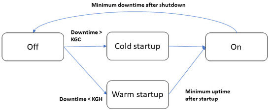
Figure 2.
Cold and hot steam turbine startup and shutdown condition.
2.7. Load Distribution between Gas Turbines’ Constraints
Load Distribution Constraint
The following set of constraints capture the fact that CCGT operators strive to achieve a similar power output among the gas turbines that operate above their technical minimum. For that purpose, we introduce the following constraints, which establish the absolute value of the difference in power output between two different gas turbines.
Note that this difference could be either positive or negative; however, if is negative, then will be positive, yielding a positive lower bound for . We leave one of the sums on purpose in order to not count the power deviation twice.
This difference in power output could be penalized in the objective function value; however, we can only take it into account if both gas turbines are actually above the technical minimum (It should not be taken into account when one gas turbine is off, and the other one is above the technical minimum,). Hence, we define binary variable , which takes a value of 1 if both gas turbines are above the technical minimum:
However, when the load distribution among the gas turbines is unequal, the steam delivered through the common collector exhibits varying thermal characteristics. This leads to temperature differences between the surface and the center of the steam turbine rotors, which can cause long-term damage.
In practical applications, maintaining an equal load distribution may not always be feasible. For instance, depending on the grid’s condition, the ISO may require more output power from a specific gas turbine unit than from others. Despite this, the ISO strives to adhere to this constraint as closely as possible during operations.
3. Results and Discussion
This section presents the analysis of two distinct numerical case studies:
(I) The first case involves a CCGT that is operational at the end of the previous day and, then, shuts down at the beginning of the analyzed day, only to restart and reach the maximum output capacity by the day’s end.
(II) The second case examines a scenario where the CCGT is initially offline on the analyzed day, but starts up later, eventually achieving maximum output capacity by the end of the day.
The input parameters for both cases are detailed in Table 1. Additionally, the startup and shutdown ramping processes for these scenarios are outlined in Table 2.

Table 1.
CCGT parameters.
Table 2.
Startup and shutdown ramps.
For the cases simulated in this work, gas turbines and steam turbines have the same characteristics. Figure 3 shows the general scheme of the CCGT plant considered for the simulations.
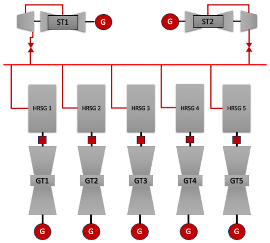
Figure 3.
The 5 × 2 CCGT scheme.
Table 3.
Gas turbines.
Table 4.
Steam turbines.
3.1. Case I
The initial conditions for the CCGT are outlined in Table 5. In Figure 4, the actual CCGT operation (discontinuous red line) is shown to deviate from the initial dispatch L due to the ramping constraints. Specifically, the model initiates a shutdown ramp in period 5, rendering the CCGT offline until period 15, followed by a hot startup ramp. Notably, the model ramps up in period 19, achieving the maximum CCGT capacity from periods 20 to 22, as necessitated by the constraint (31).
Table 5.
Initial conditions of units—Case I.
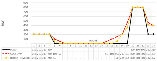
Figure 4.
CCGT power output vs. initial load for Case I.
Figure 5 displays the unitwise dispatch and auxiliary consumption. The model maintains units GT1, GT5, and ST1 online to meet the initial dispatch requirements. For starting up, it activates units GT3, GT5, and GT11, with ST2 undergoing a cold startup, necessitating at least 3 h of operation from the gas units.
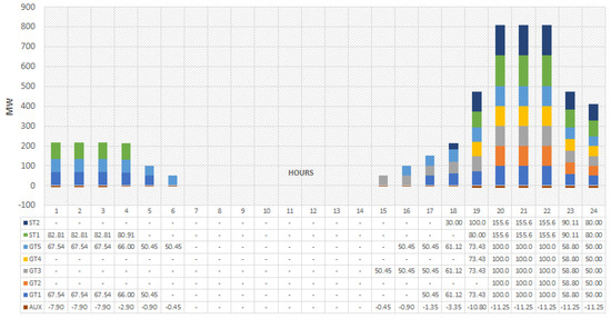
Figure 5.
Power output by unit for Case I.
Adherence to a heuristic-model-based dispatch (yellow line) leads to significant deviations from scheduled production, primarily due to the misrepresentation of the CCGT’s operational rules. Realistically, the CCGT cannot accurately follow such heuristic dispatches because of technical constraints like the operational hours’ relationship between gas and steam turbines. As per [25], deviations exceeding five percent between the heuristic and actual generation are penalized. Assuming the model’s results (discontinuous red line) represent actual generation and the penalty cost is , as per [25], this would result in a daily penalty of USD 60,957 for Case I. Such a penalty, recurring daily in scenarios like those depicted in Figure 6, represents a substantial financial burden. Furthermore, these deviations necessitate the use of costly reserves by the system operator to balance the grid. Employing a more-realistic model, like the one proposed in this paper, can prevent these costly penalties and reserve activations by enabling more-accurate dispatch decisions.
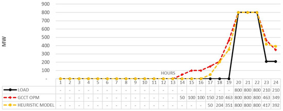
Figure 6.
CCGT power output vs. initial load for Case II.
To achieve maximum capacity during periods 20 to 22, the model strategically dispatches all units, utilizing supplementary fires to ensure the steam turbines deliver the required energy. This highlights the model’s capability to optimize unit-specific operations, a significant advancement over the heuristic simulation model. The heuristic approach, in contrast, represents the CCGT output in aggregate, failing to detail the individual contributions of each gas and steam turbine. This underscores the superiority of the proposed SEUC optimization model, which offers a more-granular and -realistic representation of CCGT operations, crucial for accurate energy management and decision-making.
3.2. Case II
In this scenario, all units begin offline, as indicated in Table 6. The results for Case II, shown in Figure 6, revealed that a warm startup is needed from periods 14 to 18 to meet the initial dispatch L. As in Case I, an increased ramp in period 19 is crucial to achieve maximum capacity from periods 20 to 22. Contrarily, the heuristic model opts for a hot startup, neglecting the prior state of the units, which could lead to long-term equipment damage and plant unavailability, thus affecting power system reliability (see Figure 1).
Table 6.
Initial conditions of units—Case II.
Calculating the penalties for Case II, as we did in Case I, we found daily penalties amounting to USD 66,093 due to discrepancies between the heuristic schedule and the actual CCGT operation. These penalties can significantly impact the power plant’s profitability and system operations, depending on the frequency of such startups annually.
As depicted in Figure 7, the startup ramp involved units GT2, GT3, and GT4, with ST2 starting in cold mode in period 18. To achieve the CCGT’s maximum capacity, all units were utilized at full output, including one supplementary fire, contributing an additional 4.75 MW.
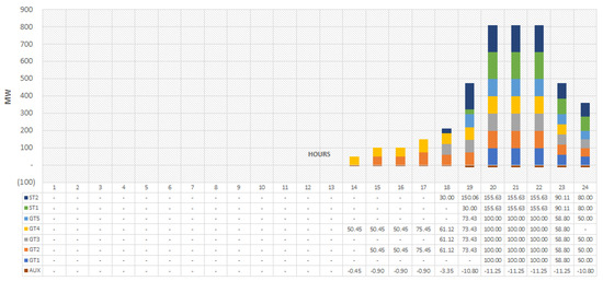
Figure 7.
Power output by unit for Case II.
4. Conclusions
In this paper, we proposed a self-unit-commitment model to optimize the dispatch of a CCGT with real operational constraints. This approach seeks to improve upon heuristic models in use currently by CCGT operators in the Colombian electric power system. We highlighted the importance for ISOs and generation companies to employ precise tools, as the model proposed in this paper, when planning operating decisions, as they can avoid economic penalties for CCGT operators, as well as deviations from the scheduled output for the ISO.
Apart from other standard constraints in the literature, we proposed an original formulation for individual gas and steam turbine units that guarantee specific characteristics of the steam. Those characteristics, which are actually in place in large CCGTs, are necessary to minimize the impact of the thermo-mechanical fatigue produced by the energy output changes required by the system operator. Employing a realistic optimization model helps to increase the useful time of the CCGT units and the reliability of the CCGT, minimizing future failures and avoiding penalties due to deviations to the program, once the output of the proposed model in this work can be followed by the CCGT in real-time. We also proposed a novel operating constraint that allows for an even load distribution among individual gas turbines—a constraint that is being imposed in real-life CCGTs.
In future research, we want to extend this work from a self- to a full-unit commitment, considering all power plants of the system. Such a model would help the ISO improve the solution of the dispatch in the Colombian power system, where CCGT plants play an important role.
Author Contributions
Conceptualization, M.G.-S. and S.W.; methodology, M.G.-S. and S.W.; software, M.G.-S.; validation, M.G.-S. and S.W.; formal analysis, M.G.-S.; investigation, M.G.-S. and S.W.; writing—original draft preparation, M.G.-S. and S.W.; writing—review and editing, M.G.-S. and S.W.; visualization, M.G.-S.; funding acquisition, S.W. All authors have read and agreed to the published version of the manuscript.
Funding
This research received no external funding.
Institutional Review Board Statement
Not applicable.
Informed Consent Statement
Not applicable.
Data Availability Statement
The data sources used are described in the article.
Acknowledgments
We would like to thank Termobarranquilla S.A. E.S.P. and the plant’s operating engineers, who shared their vast experience on combined cycle operations.
Conflicts of Interest
The authors declare no conflict of interest.
Abbreviations and Nomenclature
| Abbreviations: | |
| Combined-Cycle Gas Turbine | |
| Steam Turbine | |
| Gas Turbine | |
| Mixed-Integer Programming | |
| Unit Commitment | |
| Self-Unit Commitment | |
| Independent System Operator | |
| Indices and Sets: | |
| Hourly periods, running from 1 to T hours. | |
| Gas turbine, running from 1 to NC turbines | |
| Steam turbine, running from 1 to NS turbines | |
| Parameters: | |
| Number of hours the steam turbine have been online since the previous day | |
| Number of hours the gas turbine have been online since the previous day | |
| Defines if the unit is online or offline since the previous day | |
| Cold steam turbine ramp startup in MW | |
| Hot steam turbine ramp startup in MW | |
| Production cost a gas turbine unit in USD/MWh | |
| Cost of non-served energy USD/MWh | |
| Maximum power output of unit c (MW) | |
| Minimum power output of unit c (MW) | |
| Maximum power output of unit s (MW) | |
| Minimum power output of unit s (MW) | |
| Maximum power output of combined-cycle unit (MW) | |
| Minimum power output of combined-cycle unit (MW) | |
| Minimum number of gas units to startup one steam unit | |
| Relation of energy between steam and gas turbines (p.u.) | |
| Required load for the period t (MW) | |
| Number of minutes in one hour | |
| Shutdown time in hours to hot/warm/cold startup | |
| Number of energy hourly blocks for hot/warm/cold startup condition | |
| Energy hourly blocks for hot/warm/cold startup condition (MW) | |
| Number of shutdown energy hourly blocks | |
| Energy hourly blocks for shutdown condition (MW) | |
| Shutdown hours of the combined-cycle unit in the first period | |
| Online hours of the combined-cycle unit in the first period | |
| Power output at the last period of gas turbine c (MW) | |
| Status condition in the first period of turbine c (MW) | |
| Minimum uptime in hours | |
| Minimum downtime in hours | |
| Maximum power output of additional fire for each gas unit (MW) | |
| Up ramp rate of the gas turbine c (MW/min) | |
| Down ramp rate of the gas turbine c (MW/min) | |
| Maximum ramp-up rate (MW/h) | |
| Maximum ramp-down rate (MW/h) | |
| Startup cost of the gas turbine c (USD) | |
| Delta steam turbine cost (USD) | |
| Auxiliary consumption of the combined-cycle plant (MW) | |
| Auxiliary consumption of gas turbine unit (MW) | |
| Auxiliary consumption of steam turbine unit (MW) | |
| Minimum hours required online in gas turbines for a steam turbine startup | |
| Variables: | |
| Positive and Continuous Variables: | |
| CCGT power output above the minimum power output (MW) | |
| Power output the gas turbine c above the minimum power output (MW) | |
| Power output steam turbine s above the minimum power output (MW) | |
| Startup power output ramp CCGT below the minimum power output (MW) | |
| Shutdown power output ramp CCGT below the minimum power output (MW) | |
| Total power output CCGT (MW) | |
| Power related to the wasted steam (MW) | |
| Slack variable related with non-served power by the gas turbines when the combined-cycle unit is not coupled (MW) | |
| Combined-cycle auxiliary consumption in hour t (MW) | |
| Non-served energy by combined-cycle in hour t (MW) | |
| Power output in hour t of the additional fire of the gas turbine c (MW) | |
| Excess supplied power used during SU/SD and ramping (MW) | |
| Binary Variables: | |
| Auxiliary variable to define if the gas turbine c enable a hot startup | |
| Commitment status of the gas turbine c in hour t | |
| Commitment status of the steam turbine s in hour t | |
| Startup status of the gas turbine c in hour t | |
| Hot steam turbine startup | |
| Cold steam turbine startup | |
| Shutdown status of the gas turbine c in hour t | |
| Commitment status of the combined-cycle unit in hour t | |
| Startup status of the combined-cycle unit in hour t | |
| Shutdown status of the combined-cycle unit in hour t |
References
- Li, D.; Hu, Y.; Li, D.; Wang, J. Combined-cycle gas turbine power plant integration with cascaded latent heat thermal storage for fast dynamic responses. Energy Convers. Manag. 2019, 183, 1–13. [Google Scholar] [CrossRef]
- Fan, L.; Pan, K.; Guan, Y. A strengthened mixed-integer linear programming formulation for combined-cycle units. Eur. J. Oper. Res. 2019, 275, 865–881. [Google Scholar] [CrossRef]
- Troy, N.; Flynn, D.; Omalley, M. Multi-Mode Operation of Combined-Cycle Gas Turbines with Increasing Wind Penetration. IEEE Trans. Power Syst. 2012, 27, 484–492. [Google Scholar] [CrossRef]
- Wogrin, S.; Galbally, D.; Ramos, A. CCGT unit commitment model with first-principle formulation of cycling cost due to the fatigue damage. El Sevier-Energy 2016, 113, 227–247. [Google Scholar] [CrossRef]
- Sławiński, D.; Ziółkowski, P.; Badur, J. Thermal failure of a second rotor stage in heavy duty gas turbine. Eng. Fail. Anal. 2020, 115, 104672. [Google Scholar] [CrossRef]
- Maktouf, W.; Saï, K. An investigation of premature fatigue failures of gas turbine blade. Eng. Fail. Anal. 2015, 47, 89–101. [Google Scholar] [CrossRef]
- Consejo Nacional de Operación. Por el cual se establecen las definiciones de los parámetros técnicos de las unidades y/o plantas térmicas y los formatos para el reporte de esta información. Acuerdo 531 de 2011. April 2011. Available online: https://www.cno.org.co/content/acuerdo-531 (accessed on 1 June 2023).
- Posada, C.; Mario, C. Modelo de Optimización para las Plantas Térmicas de Generación de Ciclo Combinado en el Despacho econóMico. Master’s Thesis, Universidad Nacional de Colombia, Bogotá, Colombia, 2009. [Google Scholar]
- Liu, C.; Shahidehpour, M.; Li, Z.; Fotuhi-Firuzabad, M. Component and Mode Models for the Short-Term Schediling of Combined-Cycle Units. IEEE Trans. Power Syst. 2009, 24, 976–990. [Google Scholar]
- Lu, B.; Shahidehpour, M. Short-term scheduling of combined-cycle units. IEEE Trans. Power Syst. 2004, 19, 1616–1625. [Google Scholar] [CrossRef]
- Cohen, A.; Ostrowski, G. Scheduling units with multiple operating modes in unit commitment. IEEE Trans. Power Syst. 1996, 11, 497–503. [Google Scholar] [CrossRef]
- Bjelogrlic, M. Inclusion of combined cycle plants into optimal resource scheduling. In Proceedings of the 2000 IEEE PES Summer Meeting, Seattle, WA, USA, 16–20 July 2000; pp. 189–195. [Google Scholar]
- Mitra, S.; Sun, L.; Grossmann, I.E. Optimal scheduling of industrial combined heat and power plants under time-sensitive electricity prices. Energy 2013, 54, 194–211. [Google Scholar] [CrossRef]
- Morales-España, G.; Correa-Posada, C.M.; Ramos, A. Tight and Compact MIP Formulation of Configuration-Based Combined-Cycle Units. IEEE Trans. Power Syst. 2015, 31, 1350–1359. [Google Scholar] [CrossRef]
- Morales-España, G.; Latorre, J.M.; Ramos, A. Tight and Compact MILP Formulation of Start-Up and Shut-Down Ramping in Unit Commitment. In Proceedings of the 2013 IEEE Power & Energy Society General Meeting, Vancouver, BC, Canada, 21–25 July 2013; pp. 1288–1296. [Google Scholar]
- Morales-España, G.; Latorre, J.M.; Ramos, A. Tight and Compact MILP formulation for the Thermal Unit Commitment Problem. IEEE Trans. Power Syst. 2013, 28, 4897–4908. [Google Scholar] [CrossRef]
- Li, T.; Shaihidehpour, M. Dynamic Ramping in Unit Commitment. IEEE Trans. Power Syst. 2007, 22, 1379–1381. [Google Scholar] [CrossRef]
- Guan, Y.; Fan, L.; Yu, Y. Unified Formulations for Combined-Cycle Units. IEEE Trans. Power Syst. 2018, 33, 7288–7291. [Google Scholar] [CrossRef]
- Liu, Y.; Wu, L.; Li, J.; Chen, Y.; Wang, F. Towards accurate modeling on configuration transitions and dynamic ramping of combined-cycle units in uc problems. IEEE Trans. Power Syst. 2020, 35, 2200–2211. [Google Scholar] [CrossRef]
- Sun, X.; Luh, P.B.; Bragin, M.A.; Chen, Y.; Wan, J.; Wang, F. A novel decomposition and coordination approach for large day-ahead unit commitment with combined cycle units. IEEE Trans. Power Syst. 2018, 33, 5297–5308. [Google Scholar] [CrossRef]
- Chen, Y.; Wang, F. MIP formulation improvement for large scale security constrained unit commitment with configuration based combined cycle modeling. Electr. Power Syst. Res. 2017, 148, 147–154. [Google Scholar] [CrossRef]
- Tamayo, M.; Yu, X.; Wang, X.; Zhang, J. Configuration based Combined Cycle model in market resource commitment. In Proceedings of the 2013 IEEE Power and Energy Society General Meeting (Pes), Vancouver, BC, Canada, 21–25 July 2013; p. 5. [Google Scholar]
- Dai, C.; Chen, Y.; Wang, F.; Wan, J.; Wu, L. A Configuration-Component-Based Hybrid Model for Combined-Cycle Units in MISO Day-Ahead Market. IEEE Trans. Power Syst. 2019, 34, 883–896. [Google Scholar] [CrossRef]
- Hernandez, G.V. Desarrollo de un Modelo de Programación Óptima de Unidades de Generación de Energía Eléctrica para El Sistema Eléctrico Colombiano; Universidad Tecnológica de Pereira: Pereira, Colombia, 2015. [Google Scholar]
- Comisión de Regulación de Energía y Gas. Por la cual se reglamentan los aspectos comerciales aplicables a las transacciones internacionales de energía, que se realizan en el mercado mayorista de electricidad, como parte integrante del Reglamento de Operación. Resolución 112 de 1998. September 1998. Available online: https://gestornormativo.creg.gov.co/gestor/entorno/docs/resolucion_creg_0112_1998.htm (accessed on 1 June 2023).
Disclaimer/Publisher’s Note: The statements, opinions and data contained in all publications are solely those of the individual author(s) and contributor(s) and not of MDPI and/or the editor(s). MDPI and/or the editor(s) disclaim responsibility for any injury to people or property resulting from any ideas, methods, instructions or products referred to in the content. |
© 2023 by the authors. Licensee MDPI, Basel, Switzerland. This article is an open access article distributed under the terms and conditions of the Creative Commons Attribution (CC BY) license (https://creativecommons.org/licenses/by/4.0/).