Abstract
This work uses a hole-transporting copper cobaltite/copper oxide nanocomposite to fabricate carbon-based MAPbI3 PSCs. The copper cobaltite/copper oxide HTM-based PSC results show the highest power conversion efficiency (PCE = 7.32%) compared with an HTM-free device. The highest photocurrent density (Jsc = 15.17 mA/cm2), open-circuit voltage (Voc = 0.82 V), and fill factor (FF = 0.59) are achieved for the PSC fabricated with hydrothermally synthesized copper cobaltite/copper oxide nanocomposites. Electrochemical impedance spectroscopy is used to analyze the charge transfer resistance (Rs) and the capacitive behavior of copper cobaltite/copper oxide nanocomposite. The maximum electron lifetime of 35.16 μs is witnessed for the PSCs fabricated with 3 mg mL−1 of copper cobaltite/copper oxide (H1). The efficiency of the copper cobaltite/copper oxide-based PSC remains unchanged, showing no further perovskite layer degradation.
1. Introduction
In recent years, perovskite solar cells (PSCs) have attracted much interest because of their photophysical features, such as wide diffusion length (∼1 μm), high charge carrier mobility (>100 cm2/Vs), high absorption coefficient (>105 cm−1), and an amazing power conversion efficiency (PCE) of more than 25.7% [1,2,3,4]. PSCs are fabricated in different device configurations, such as planar (n-i-p) and inverted planar (p-i-n). In a typical planar cell, TiO2 and spiro-OMeTAD materials are used as electron transport material (ETM) and hole transport material (HTM) in the PSCs, respectively [5,6,7,8,9]. Nevertheless, spiro-OMeTAD HTM is very expensive and is unstable under light and humidity [10,11]. Moreover, pristine spiro-OMeTAD has low hole mobility and less conductivity because of its triangular pyramid configuration and larger intermolecular distance [12]. Dopants, such as lithium bis (trifluoromethanesulfonyl)-imide and cobaltic complexes, are typically added to spiro-OMeTAD to increase the hole mobility [13,14,15,16], even though the added ionic salts are hygroscopic and, therefore, decompose the perovskite film [17]. Similarly, 4-tertButylpyridine (TBP) is a dopant when used with spiro-OMeTAD; it reacts with perovskite and decomposes into PbI2 [18]. To increase the device stability, several efforts have been made to create dopant-free HTM [19,20,21]. In addition, inorganic semiconductors (p-type), such as copper (I), thiocyanate (CuSCN), copper iodide (CuI), copper oxides (Cu2O and CuO), cobalt oxide (Co3O4), and nickel oxides (NiO), are promising HTM for PSCs due to their unique properties, including ease of fabrication with low cost, wide bandgap, suitable energy levels, high hole mobility, and chemical stability [22,23,24,25,26,27,28,29,30,31]. In 2014, Gratzel et al. constructed a PSC device using CuSCN HTM in a planar structure and achieved a PCE of 12.4% [32]. Guo et al. reported a hybrid HTM (FBT-Bh4/CuOx) with an excellent PSC with enduring stability and a PCE of 18.85% [33]. Solvents, such as diethyl sulfide and di-isopropyl sulfide, are used in the preparation of inorganic HTMs, which are toxic, high polar in nature, and can quickly decompose the perovskite film.
Alternatively, ternary metal oxides have multiple oxidation states, which is an advantage for tuning the electrical and optical properties. The ternary metal oxides are classified as perovskite (ABX3) [34], spinel (AB2X4) [35], delafossite (ABX2) [36], and scheelite (ABX4) [37] structures on the basis of the composition and crystalline structure. Among them, the spinel form is an important class of HTL in PSCs [38,39]. The advantages of using spinel as HTL in PSC include their activity, widespread availability, low cost, easy synthesis, thermodynamic stability, low electrical resistance, and environmental friendliness [40]. Typical spinel structure are briefly described as AB2X4 (A = Co, Mn, Cd, Li, Cu, Ge, Zn, Mg, Ni, Fe, Ca, or Ba; B = Al, Cr, Mn, Fe, Co, Ni, Ga, In, or Mo; and X = O, S, Se, Te, or N), where A occupies the centers of tetrahedrally coordinated sites, B occupies the centers of octahedrally coordinated sites, and X is the position at the polyhedral vertexes [41]. Spinel oxides of chemical composition are denoted as AB2O4, where A2+ represents divalent metal ion, B3+ denotes trivalent metal ion, and O2− represents anions. The crystal structure of spinel oxide has cubic symmetry with the Fd3m space group. In PSCs, mainly CuGaO2-, CuFeO2-, or CuCrO2-based ternary metal oxides have been exploited as HTMs. Recently, ternary metal oxide (CuCrO2) was used as a HTM in PSCs and ultimately achieved the PCE of 17.19% [42,43,44]. Similarly, PCE of 18.51% was achieved when CuGaO2 nanoplatelets were used as HTM in PSCs [42]. In 2019, Seckin et al. employed CuFeO2 nanoparticles as HTM in planar PSCs, and PCE of 15.6% was observed with negligible hysteresis [43]. Nickel cobalt oxide (NiCo2O4) is a p-type semiconductor having spinel structure and exhibits mixed-valence oxide (Ni placed only in octahedral sites but Co placed in both octahedral and tetrahedral sites). NiCo2O4 has a conductivity of 500 S/cm, which is claimed to be the highest value as compared with transparent conducting oxide (TCO) [45,46]. In 2020, Bashir et al. reported the PCE of >14% with long-term stability when spinel NiCo2O4 nanoparticles were used as an HTL in PSCs [38]. Mixed-metal oxide nanocomposites have exhibited high conductivity as well as good stability [47,48,49]. PSC with mixed-metal oxide nanocomposites show equal or higher efficiency than that of the reference PSC (spiro-OMeTAD) [50]. In recent times, a conductive and transparent p-i-n PSCs with CuAlO2/CuO HTL was utilized, and the PCE of 16.3% with negligible hysteresis was observed [51]. Seckin Akin et al. reported that ternary metal oxide CuCrO2 was hydrothermally synthesized and employed as an HTM layer in planar-structured PSCs with PCE of 16.7% [52]. Hua Zang et al. demonstrated the lower temperature solution process for making CuCrO2 and employed as an HTM in p-i-n structured PSCs with compared with NiOx. The CuCrO2 HTM-based device shows higher PCE of 19.0% [53]. Bo-Rong jheng et al. reported the synthesis of ZnCo2O4 by chemical precipitation method and employed spinel ZnCo2O4 NPs as the HTM for the fabrication of p-i-n PSCs, achieving a PCE of 12.31% [54]. J.H. Lee et al. reported the solution-processed spinel CuCo2O4 and used it as a hole transport layer in high-performance perovskite solar cells. By optimizing the annealing temperature, opto-electrical properties were finely controlled, which led to 14.12% PCE in inverted planar PSCs. Another advantage of CuCo2O4-based HTM is having negligible hysteresis of J-V scan that brought about a highly stable and reliable photovoltaic performance [55]. In general, spinel copper cobaltite (CuCo2O4) nanoparticles were prepared by various methods, such as hydrothermal, microwave, co-precipitation, sol–gel, chemical bath deposition, and electrodeposition methods [56,57,58,59,60,61,62].
In spite of being a strong choice for feasible HTMs in PSCs, there has been no research on the usage of copper cobaltite/copper oxide nanocomposite as an HTM for planar PSCs. Hence, for the first time to the best of our knowledge, we explored the use of copper cobaltite/copper oxide HTM synthesized by chemical method as stable and low-cost inorganic HTM in PSCs. It is assumed that the incorporation of specific material greatly enhances the PCE with enduring stability. In this work, inorganic copper cobaltite/copper oxide material is used for the fabrication of low cost and highly stable PSCs. The optimized condition of the synthesized HTM-based PSC device shows highest efficiency as compared with HTM-free device. The highest performance of the copper cobaltite/copper oxide HTM-based device shows a conversion efficiency of 7.32%. More importantly, the fabricated device with copper cobaltite/copper oxide HTM exhibits excellent stability in atmospheric conditions as compared with the device with P3HT HTM.
2. Materials and Methods
2.1. Materials
Copper nitrate trihydrate, cobalt nitrate hexahdrate, sodium hydroxide, methylammonium lead iodide complex, dimethyl sulfoxide, N, N-dimethylformamide and dichlorobenzene were used as received. TiO2 paste, carbon paste, and FTO glass substrate (~16 Ω/sq) were procured from Dyenamo, Sweden.
2.2. Synthesis of Copper Cobaltite/Copper Oxide Nanocomposite
2.2.1. Precipitation Method
First, 100 mL aqueous solutions of 0.1 M of copper nitrate hexahydrate and 0.2 M of cobalt nitrate trihydrate were prepared separately and continuously stirred for approximately 30 min before mixing them. Then, 0.6 M of sodium hydroxide was added into the above aqueous solution, and the precipitate was formed. The obtained precipitate was washed well with DD water and finally with ethanol. The precipitate was kept in a hot air oven at 80 °C to remove moisture, and then the dried sample was sintered at 600 °C for 3 h. The prepared material is named P1.
2.2.2. Microwave Method
In the case of microwave synthesis of copper cobaltite/copper oxide nanocomposite, the above solution was transferred into the reagent bottle. Then, the reagent bottle was kept in a microwave oven at a frequency of 2.45 GHz with the power of 560 W for 10 min and then cooled naturally. The collected precipitate was air-dried at 80 °C, and then the powder was sintered at 600 °C for 3 h. The prepared material is named M1.
2.2.3. Hydrothermal Method
In hydrothermal method, the experimental procedure similar to the precipitation method was adopted for the synthesis of copper cobaltite/copper oxide nanocomposite. The prepared solution was taken into the Teflon-lined stainless steel autoclave and kept at 160 °C in an oven for 16 h, allowing hydrothermal reaction to complete. The precipitate was washed with DD water and ethanol. The collected precipitate was air-dried at 80 °C and then sintered at 600 °C for 3 h. The prepared sample is named H1.
2.3. Fabrication of Perovskite Solar Cell
The FTO substrate (1.5 × 1.5 cm) was patterned for the fabrication of solar cells, and the cell active area of 0.75 cm2 was fixed. Then, the FTO substrates were ultrasonically cleaned with detergent, acetone, ethanol, and double-distilled water for 10 min, sequentially. After cleaning, the FTO substrates were treated with UV and ozone for approximately 15 min. The cleaned substrate was soaked in 40 mM titanium tetrachloride solution (50 mL) at 70 °C for 30 min. Subsequently, the substrate was dried at 120 °C for 15 min, resulting in the formation of a compact-TiO2 (c-TiO2) layer on FTO-coated glass. Commercial mesoporous-TiO2 (m-TiO2) paste was diluted using ethanol at a ratio of 1:3 (w/w), which was coated on c-TiO2/FTO glass substrate. Perovskite (methyl ammonium lead iodide) layer was coated on m-TiO2/c-TiO2/FTO glass substrate by spin-coating method (4000 rpm for 30 s). In continuance, 11 s prior to the last step of the reaction, 500 μL of dichlorobenzene was quickly added by spin-coating method. After that, perovskite-coated substrate was heated at 100 °C for 10 min. Copper cobaltite/copper oxide HTM was dispersed with dichlorobenzene at concentrations of 1mg, 3 mg, and 5 mg, which were coated on a perovskite layer with spin speeds of 1000 rpm, 1500 rpm, and 2000 rpm for 30 s and then heated at 120 °C for 10 min. Carbon was used as back electrode, which was coated on HTL by doctor-blade method. Finally, the fabricated device was heated under 120 °C for approximately 30 min. The schematic representation of the fabricated device is shown in Figure 1.
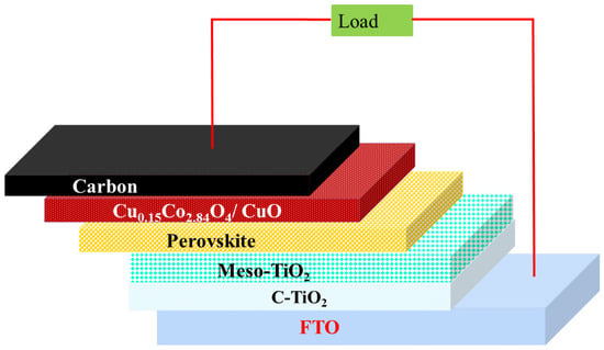
Figure 1.
Schematic diagram of the device structure.
2.4. Characterization
Crystal structure of the prepared copper cobaltite/copper oxide nanocomposite was analyzed by PAN analytic X’Pert Pro powder XRD. The chemical nature of the prepared copper cobaltite/copper oxide nanocomposite was analyzed by using STR 500 mm focal length laser Raman spectrometer. The morphology of the synthesized nanocomposite was observed by using CAREL ZEISS EVO18 Microscope and JEOL-2100+HRTEM. The chemical composition of the synthesized nanocomposite was investigated by PHI-VERSAPROBE III-XPS. Electrochemical Impedance analysis was carried out by SP-200 electrochemical workstation. The fabrication process was carried out using Dyenamo tool box under air mass of 1.5 solar illuminated at 100 mWcm−2.
3. Results
To understand the crystal structure and phase of the as-developed materials, the XRD analyses were carried out. XRD patterns of the prepared copper cobaltite/copper oxide nanocomposites are presented in Figure 2. All the diffraction peaks observed at 18.99°, 31.27°, 36.84°, 44.81°, 55.65°, 59.35°, and 65.23° correspond to (111), (220), (311), (400), (422), (511), and (440) planes, respectively. The observed peaks coincide with JCPDS data (Card No. #01-078-2172) and could be indexed to cubic phase (Fd3m), a = b = c = 8.0840 Å, and α = β = γ = 90° of Cu0.15Co2.84O4. Additionally, more diffraction peaks were observed at 35.55°, 38.74°, 48.70°, 58.30°, and 67.94°, which correspond to (−111), (111), (−202), (202), and (113) planes, respectively, which is related to the JCPDS data (Card No. # 01-089-5898) and could be indexed to monoclinic phase (C2/c), a = 4.6900 Å, b = 3.4200 Å, c = 5.1310 Å, and α = γ = 90°, β = 99.54°. This confirms the formation of copper oxide (Figure 2). The resulting XRD pattern was used to confirm the formation of multiphase crystalline structure. The same crystal phase was observed for the samples (P1), (M1), and (H1).
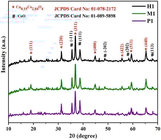
Figure 2.
Powder X-ray diffraction patterns of copper cobaltite/copper oxide nanocomposite.
Raman spectra of spinel copper cobaltite/copper oxide nanocomposite materials P1, M1, and H1 are shown in Figure 3. The copper cobaltite/copper oxide nanocomposite shows five typical peaks of copper cobaltite at approximately 194 cm−1, 479 cm−1, 516 cm−1, 615 cm−1, and 685 cm−1. The three peaks at 194 cm−1, 516 cm−1, and 615 cm−1 correspond to F2g modes, and another two peaks at 479 cm−1 and 685 cm−1 belong to Eg and A1g modes of copper cobaltite, respectively [63]. The peak at 479 cm−1 corresponds to the stretching mode of the Co–O bond, which is due to the tetrahedral sites of Co3+–O2−. Furthermore, the peak at 516 cm−1 is due to the stretching vibrations of the Cu–O bond from octahedral sites of Cu2+–O2−. The peaks at 685 cm−1 and 615 cm−1 confirm the existence of spinel-structured copper cobaltite. Raman analysis confirmed the existence of spinel structure of copper cobaltite in the nanocomposite.
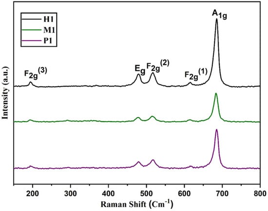
Figure 3.
Raman spectra of spinel copper cobaltite/copper oxide nanocomposite materials P1, M1, and H1.
The structure and morphology of the prepared copper cobaltite/copper oxide nanocomposite was observed using SEM and TEM techniques. The SEM image clearly explained the surface morphologies of the nanomaterials. The SEM image of synthesized copper cobaltite/copper oxide nanocomposite is shown in Figure 4. The synthesized copper cobaltite/copper oxide nanocomposite by three different methods, namely precipitation (P1), microwave (M1), and hydrothermal (H1), exhibited the homogeneous morphology with agglomerated nanoparticles.
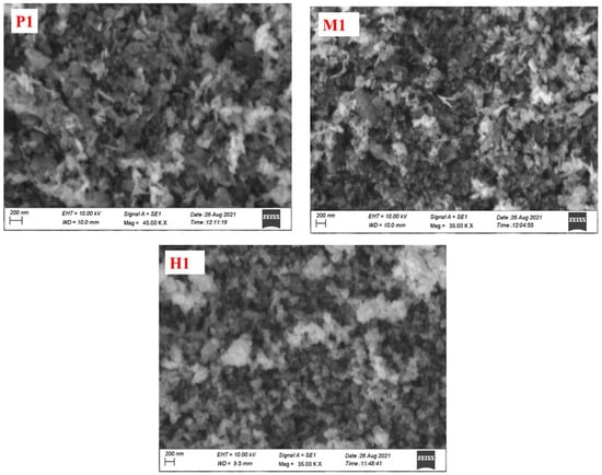
Figure 4.
SEM micrograph images of spinel copper cobaltite/copper oxide nanocomposite of P1, M1, and H1.
The detailed structure and morphology of copper cobaltite/copper oxide nanocomposite were analyzed by TEM, HR-TEM, and SAED, as shown in Figure 5. The particle size of 60 nm was observed for copper cobaltite/copper oxide nanocomposite. HR-TEM images of copper cobaltite/copper oxide nanocomposite in Figure 5c–e show that the lattice spacing of 0.46 nm belongs to the (111) plane, 0.28 nm corresponds to the (220) diffraction plane of spinel copper cobaltite (Cu0.15Co2.84O4), and 0.23 nm corresponds to the (111) plane of copper oxide (CuO). Diffraction rings corresponding to the planes (111), (220), (311), and (400) in the SAED pattern of Figure 5f confirms the formation of copper cobaltite/copper oxide nanocomposite.
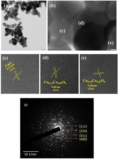
Figure 5.
HR-TEM image of copper cobaltite/copper oxide nanocomposite (H1), (a) TEM image, (b) high-resolution TEM image, (c–e) magnified HR-TEM image, and (f) SAED pattern.
Figure 6a–d display the XPS spectra of copper cobaltite/copper oxide nanocomposite. Figure 6a denotes the survey spectrum of copper cobaltite/copper oxide nanocomposite, which confirms the presence of Cu 2p (935.13 eV), Co 2p (780.39 eV), O 1s (530.06 eV), and C 1s (285.09 eV), respectively.
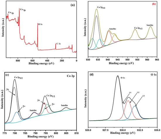
Figure 6.
XPS spectra of copper cobaltite/copper oxide nanocomposite (H1) (a) wide spectra, (b) Cu 2p, (c) Co 2p, and (d) O 1s.
XPS of Cu 2p is shown in Figure 6b. The spectrum of Cu 2p shows three peaks at 932.15 eV, 934.22 eV, and 935.8 eV for Cu 2p3/2 and two satellite peaks at 940.46 eV and 943.54 eV for Cu 2p3/2. In addition, two more peaks were observed at 953.86 eV for Cu 2p1/2 and 961.72 eV, corresponding to satellite peak of Cu 2p1/2 [63,64]. The Co 2p3/2 region in Figure 6c shows two peaks at 779.72 eV and 780.78 eV, corresponding to the octahedral Co3+ and tetrahedral Co2+, respectively. In addition, two peaks at 794.23 eV and 795.61 eV belong to Co 2p1/2, which corresponds to the octahedral site of Co3+ and tetrahedral site of Co2+ ions. The satellite peak at 789.42 eV in Co 2p3/2 and another satellite peak at 804.78 eV in Co 2p1/2 region were identified [65,66]. Figure 6d shows O 1s exhibited three peaks at 531.70 eV, 530.77 eV, and 529.26 eV, which correspond to surface oxygen, metal–oxygen (Cu and Co), and lattice O2−, respectively [67,68]. The XPS spectra clearly demonstrated that the surface of the nanocomposite contained Cu 2p and Co 2p ions, which confirms the formation of copper cobaltite/copper oxide nanocomposite.
The photovoltaic performance of the perovskite solar cell (PSC) was investigated under sunlight illumination. The prepared copper cobaltite/copper oxide nanocomposite was used as a HTM for the PSC. The prepared copper cobaltite/copper oxide nanocomposite (H1) was deposited on the perovskite layer by the spin-coating technique at three different concentrations, namely 1mg, 3mg, and 5mg, and three different spin speeds from 1000 to 2000 rpm. The PV parameters of copper cobaltite/copper oxide nanocomposite (H1)-based PSC with different spin speeds and solution concentrations are presented in Table S1, and its J-V curves are also shown in Figure S1. At the beginning, PCE of copper cobaltite/copper oxide HTM-based PSC increases with the increase in spin speed and concentrations. When the HTM concentration is increased from 1–3 mg mL−1 and spin speed from 1000–1500 rpm, the device experienced better performance, yielding an open-circuit voltage (Voc) = 0.82 V, photo current density (Jsc) = 15.17 mA cm−2, fill factor (FF) = 0.59, and PCE of 7.32% in the reverse scan. Further, an increase in copper cobaltite/copper oxide concentrations and spin speed greater than 3 mg mL−1 and 1500 rpm decreases the performance of the device. Therefore, an optimal copper cobaltite/copper oxide concentration and spin speed of 3 mg mL−1 and 1500 rpm was followed for H1-, P1-, and M1-based copper cobaltite/copper oxide PSCs, as shown in Figure 7a–d.
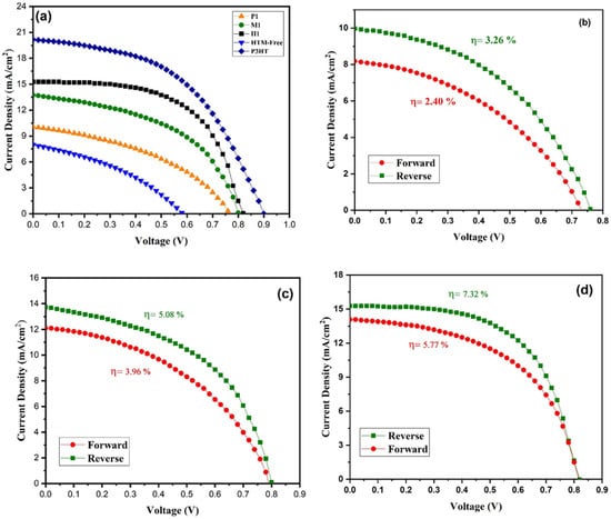
Figure 7.
(a) J-V Curves of P1-, M1-, and H1-based PSC, standard P3HT device, and hole-transport-material-free device. Forward and reverse J-V curves for (b) P1-, (c) M1- and (d) H1-based PSC.
For comparison, different PSCs were fabricated with HTM (P3HT) and without HTM. The best PCEs of the devices with P3HT and without HTM were 8.91 and 1.76%, respectively, and the respective values are represented in Table 1. The crucial role of copper cobaltite/copper oxide on the photogenerated charge collection in the planar PSC is evident.

Table 1.
Photovoltaic parameters for P1-, M1-, and H1-based PSC, standard P3HT device, and hole-transport-material-free device.
As compared with standard P3HT-based device, copper cobaltite/copper oxide HTM-based cells delivered a relatively lower Voc. The little decrease in Voc may be expected from some recombination path, which occurs at the perovskite/HTM interface. Thus, there could be a small interfacial issue in the perovskite film with the copper cobaltite/copper oxide HTM.
Moreover, the performance of H1-based PSC was compared with M1- and P1-based PSCs and is represented in Table 1. The PCE of M1-based PSC was 5.08%, Jsc = 13.81 mA/cm2, Voc = 0.80 V, and FF = 0.46. The P1-based PSC device delivered Jsc = 10.10 mA/cm2, Voc = 0.76 V, FF = 0.39, and PCE of 3.20%. As a result, H1-based PSC exhibited good performance compared with both M1- and P1-based PSCs due to its better interfacial contact between the layers.
Hysteresis plays an important role in the performance of PSCs. The forward and the reverse scan of J-V curves for copper cobaltite/copper oxide nanocomposite (P1, M1, and H1)-based PSCs are shown in Figure 7b–d, and the hysteresis parameters are listed in Table 1. P1-, M1-, and H1-based devices exhibited hysteresis behavior in the forward and reverse scan of J-V curve due to their ion migration and recombination of electrons from the interfacial trap states. Thus, the J-V hysteresis behavior is estimated by using the Formula (1) of hysteresis index (HI).
where PCEReverse is a power conversion efficiency of reverse scan, and PCEForward is a power conversion efficiency of forward scan. The hysteresis index was closer to zero (0 < HI < 1), and the PSC with the H1-based HTM showed a small hysteresis index value, which indicates that the device had lower hysteresis behavior and a significantly higher PCE value of 7.32%. The forward and reverse scans for standard P3HT device and hole-transport-material-free PSCs are shown in Figure S2, and the corresponding hysteresis parameters are listed in Table 1. Undoubtedly, the fabricated device containing copper cobaltite as a HTM showed better performance because of its better hole collection between the interfaces.
In order to examine the charge transfer resistance (Rs) and interfacial properties of the PSC, the electrochemical impedance spectroscopy was used. EIS was measured for the copper cobaltite/copper oxide nanocomposite (P1-, M1-, and H1)-based PSC and HTM-free devices under dark conditions. Figure 8a shows Nyquist plots, and the circuit model is inserted in the figure. The Nyquist plot of the device exhibits two semi-circles. The high-frequency region represents series resistance (Rs), and the low frequency region represents recombination resistance (Rrec). The impedance parameters are summarized in Table 2. The higher recombination resistance of 7074 Ω was observed for the H1-based device as compared with the M1- and P1-based devices and HTM-free device. The enhances the recombination resistance, which suppresses the recombination between the interfaces and improves the power conversion efficiency.
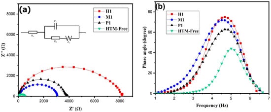
Figure 8.
EIS of P1-, M1-, and H1-based PSC device and hole-transport-material-free device: (a) Nyquist plot and (b) Bode plot.
Table 2.
Electrochemical impedance parameters for P1-, M1-, and H1-based PSC device and HTM-free device.
Moreover, the charge carrier lifetime (τ) influences PSCs performance, which is calculated from the Bode plot (Figure 8b). The charge carrier lifetime (τ) of the device was calculated using the Equation (2) [69], and the data are presented in Table 2.
where τ is carrier lifetime, fmax is frequency maximum, and π is constant. The maximum carrier life time of 35.16 μs was observed for the H1-based PSC. As a result, the H1-based PSC showed better performance due to its hole extraction, high carrier lifetime, and higher recombination resistance, which led to an increase in the photovoltaic performance.
The performance and stability of copper cobaltite/copper oxide layer-based PSC and P3HT-based PSC were evaluated, and the corresponding results are shown in Figure 9. The fabricated H1-based PSC and P3HT-based devices were exposed to an open environment for several days without any encapsulation, and finally the performance was measured. From Figure 9, the efficiency of the P3HT-based device retained 60% of its initial PCE under room atmosphere. The efficiency of the PSC with copper cobaltite/copper oxide layer remained unchanged and retained 80% of its initial PCE, which indicated there was no further degradation of perovskite layer in the device. Thus, the copper cobaltite/copper oxide layer resisted the penetration of moisture and provided an extra stability against the moisture. Moreover, the use of carbon back electrode also increased the stability of the device due to its suitable encapsulation of PSC, which was proven in our earlier studies [70].
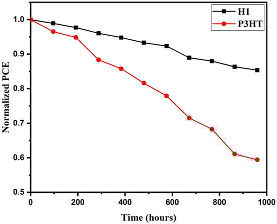
Figure 9.
Stability of normalized PCE of H1-based PSC and P3HT.
4. Discussion
In this research work, copper cobaltite/copper oxide nanocomposites are successfully synthesized by precipitation, microwave, and hydrothermal methods. The prepared copper cobaltite/copper oxide nanocomposite has a mixed crystalline phase, which comprises a cubic phase of copper cobaltite and a monoclinic phase of copper oxide. The synthesized copper cobaltite/copper oxide nanocomposites (P1, M1, and H1) were used as an HTM for the FTO/C-TiO2/meso-TiO2/perovskite/copper cobaltite–copper oxide/carbon device. The synthesized copper cobaltite/copper oxide nanocomposite was used as an HTL in the n-i-p structure. Hydrothermal driven synthesis of copper cobaltite/copper oxide nanocomposite (H1) delivers the best PCE of 7.32%. The copper cobaltite/copper oxide nanocomposite-based device exhibited much improved PCEs as compared with the HTM-free device. In addition, EIS shows the higher recombination resistance (7074 Ω) for the H1-based device, and the fabricated device remains stable even after 960 h. The present work clearly reveals that the hydrothermal driven copper cobaltite/copper oxide nanocomposite is an efficient and stable HTM for planar PSCs.
Supplementary Materials
The following supporting information can be downloaded at: https://www.mdpi.com/article/10.3390/en16093696/s1, Figure S1: J-V curve of H1 based PSC device (a) 1000 rpm (b) 1500 rpm and (c) 2000 rpm spin speed; Figure S2: Forward and Reverse J-V curve for (a) P3HT based device (b) HTM-free device; Table S1: Photovoltaic parameters for H1 based PSC device.
Author Contributions
Conceptualization, K.P.M., V.A., S.T., T.H.O. and S.K.; Methodology, K.P.M., V.A., A.N., S.T., T.H.O. and S.K.; Validation, V.A., A.N., S.T., T.H.O. and S.K.; Formal analysis, K.P.M. and V.A.; Investigation, K.P.M. and V.A.; Resources, S.K.; Data curation, K.P.M., V.A. and S.K.; Writing—original draft, K.P.M.; Writing—review & editing, A.N., S.T., T.H.O. and S.K.; Supervision, S.K.; Project administration, S.K.; Funding acquisition, S.K. All authors have read and agreed to the published version of the manuscript.
Funding
The authors gratefully acknowledge the MHRD-RUSA Phase I, G.O. (Ms) No. 139/Higher Education (A1) Department, Dated: 12.10.2020, for financial support. This article was written with the partial financial support of RUSA-phase 2.0 grants sanctioned vide letter. F. No. 24–51/2014-U, policy (TN multi- Gen), Dept. of Edn., Govt of India, Dated: 9 October 2018.
Data Availability Statement
Not applicable.
Acknowledgments
The authors gratefully acknowledge the MHRD-RUSA Phase I, G.O. (Ms) No. 139/Higher Education (A1) Department, Dated: 12.10.2020, for financial support. This article was written with the partial financial support of RUSA-phase 2.0 grants sanctioned vide letter. F. No. 24–51/2014-U, policy (TN multi- Gen), Dept. of Edn., Govt of India, Dated: 9 October 2018.
Conflicts of Interest
The authors declare no conflict of interest.
References
- Ma, L.; Hao, F.; Stoumpos, C.C.; Phelan, B.T.; Wasielewski, M.R.; Kanatzidis, M.G. Carrier Diffusion Lengths of over 500 nm in Lead-Free Perovskite CH3 NH3 SnI3 Films. J. Am. Chem. Soc. 2016, 138, 14750–14755. [Google Scholar] [CrossRef]
- Herz, L.M. Charge-Carrier Mobilities in Metal Halide Perovskites: Fundamental Mechanisms and Limits. ACS Energy Lett. 2017, 2, 1539–1548. [Google Scholar] [CrossRef]
- Xing, G.; Mathews, N.; Sun, S.; Lim, S.S.; Lam, Y.M.; Grätzel, M.; Mhaisalkar, S.; Sum, T.C. Long-Range Balanced Electron- and Hole-Transport Lengths in Organic-Inorganic CH3NH3PbI3. Science 2013, 342, 344–347. [Google Scholar] [CrossRef]
- Kim, M.; Jeong, J.; Lu, H.; Lee, T.K.; Eickemeyer, F.T.; Liu, Y.; Choi, I.W.; Choi, S.J.; Jo, Y.; Kim, H.-B.; et al. Conformal quantum dot–SnO 2 layers as electron transporters for efficient perovskite solar cells. Science 2022, 375, 302–306. [Google Scholar] [CrossRef] [PubMed]
- Karuppuchamy, S.; Andou, Y.; Endo, T. Preparation of nanostructured TiO2 photoelectrode for flexible dye-sensitized solar cell applications. Appl. Nanosci. 2013, 3, 291–293. [Google Scholar] [CrossRef]
- Noori, L.; Hoseinpour, V.; Shariatinia, Z. Optimization of TiO2 paste concentration employed as electron transport layers in fully ambient air processed perovskite solar cells with a low-cost architecture. Ceram. Int. 2022, 48, 320–336. [Google Scholar] [CrossRef]
- Okada, N.; Karuppuchamy, S.; Kurihara, M. An Efficient Dye-sensitized Photoelectrochemical Solar Cell Made from CaCO3 -coated TiO2 Nanoporous Film. Chem. Lett. 2005, 34, 16–17. [Google Scholar] [CrossRef]
- Choi, J.; Song, S.; Hörantner, M.T.; Snaith, H.J.; Park, T. Well-Defined Nanostructured, Single-Crystalline TiO2 Electron Transport Layer for Efficient Planar Perovskite Solar Cells. ACS Nano 2016, 10, 6029–6036. [Google Scholar] [CrossRef]
- Ramachandran, K.; Jeganathan, C.; Karuppuchamy, S. Surfactant assisted electrochemical growth of ultra-thin CuSCN nanowires for inverted perovskite solar cell applications. Org. Electron. 2021, 95, 106214. [Google Scholar] [CrossRef]
- Gil, B.; Yun, A.J.; Lee, Y.; Kim, J.; Lee, B.; Park, B. Recent Progress in Inorganic Hole Transport Materials for Efficient and Stable Perovskite Solar Cells. Electron. Mater. Lett. 2019, 15, 505–524. [Google Scholar] [CrossRef]
- Rombach, F.M.; Haque, S.A.; Macdonald, T.J. Lessons learned from spiro-OMeTAD and PTAA in perovskite solar cells. Energy Environ. Sci. 2021, 14, 5161–5190. [Google Scholar] [CrossRef]
- Bakr, Z.H.; Wali, Q.; Fakharuddin, A.; Schmidt-Mende, L.; Brown, T.M.; Jose, R. Advances in hole transport materials engineering for stable and efficient perovskite solar cells. Nano Energy 2017, 34, 271–305. [Google Scholar] [CrossRef]
- Fabregat-Santiago, F.; Bisquert, J.; Cevey, L.; Chen, P.; Wang, M.; Zakeeruddin, S.M.; Grätzel, M. Electron Transport and Recombination in Solid-State Dye Solar Cell with Spiro-OMeTAD as Hole Conductor. J. Am. Chem. Soc. 2009, 131, 558–562. [Google Scholar] [CrossRef] [PubMed]
- Snaith, H.J.; Grätzel, M. Enhanced charge mobility in a molecular hole transporter via addition of redox inactive ionic dopant: Implication to dye-sensitized solar cells. Appl. Phys. Lett. 2006, 89, 262114. [Google Scholar] [CrossRef]
- Abate, A.; Hollman, D.J.; Teuscher, J.; Pathak, S.; Avolio, R.; D’Errico, G.; Vitiello, G.; Fantacci, S.; Snaith, H.J. Protic Ionic Liquids as p-Dopant for Organic Hole Transporting Materials and Their Application in High Efficiency Hybrid Solar Cells. J. Am. Chem. Soc. 2013, 135, 13538–13548. [Google Scholar] [CrossRef]
- Leijtens, T.; Lim, J.; Teuscher, J.; Park, T.; Snaith, H.J. Charge Density Dependent Mobility of Organic Hole-Transporters and Mesoporous TiO2 Determined by Transient Mobility Spectroscopy: Implications to Dye-Sensitized and Organic Solar Cells. Adv. Mater. 2013, 25, 3227–3233. [Google Scholar] [CrossRef]
- Nguyen, W.H.; Bailie, C.D.; Unger, E.L.; McGehee, M.D. Enhancing the Hole-Conductivity of Spiro-OMeTAD without Oxygen or Lithium Salts by Using Spiro(TFSI)2 in Perovskite and Dye-Sensitized Solar Cells. J. Am. Chem. Soc. 2014, 136, 10996–11001. [Google Scholar] [CrossRef]
- Niu, G.; Guo, X.; Wang, L. Review of recent progress in chemical stability of perovskite solar cells. J. Mater. Chem. A 2015, 3, 8970–8980. [Google Scholar] [CrossRef]
- Azmi, R.; Nam, S.Y.; Sinaga, S.; Akbar, Z.A.; Lee, C.-L.; Yoon, S.C.; Jung, I.H.; Jang, S.-Y. High-performance dopant-free conjugated small molecule-based hole-transport materials for perovskite solar cells. Nano Energy 2018, 44, 191–198. [Google Scholar] [CrossRef]
- Heo, J.H.; Park, S.; Im, S.H.; Son, H.J. Development of Dopant-Free Donor–Acceptor-type Hole Transporting Material for Highly Efficient and Stable Perovskite Solar Cells. ACS Appl. Mater. Interfaces 2017, 9, 39511–39518. [Google Scholar] [CrossRef]
- Lee, J.; Malekshahi Byranvand, M.; Kang, G.; Son, S.Y.; Song, S.; Kim, G.-W.; Park, T. Green-Solvent-Processable, Dopant-Free Hole-Transporting Materials for Robust and Efficient Perovskite Solar Cells. J. Am. Chem. Soc. 2017, 139, 12175–12181. [Google Scholar] [CrossRef] [PubMed]
- Ramachandran, K.; Jeganathan, C.; Subbian, K. One-step electrodeposition of CuSCN/CuI nanocomposite and its hole transport-ability in inverted planar perovskite solar cells. Nanotechnology 2021, 32, 325402. [Google Scholar] [CrossRef]
- Chen, J.; Park, N.-G. Inorganic Hole Transporting Materials for Stable and High Efficiency Perovskite Solar Cells. J. Phys. Chem. C 2018, 122, 14039–14063. [Google Scholar] [CrossRef]
- Sepalage, G.A.; Meyer, S.; Pascoe, A.; Scully, A.D.; Huang, F.; Bach, U.; Cheng, Y.-B.; Spiccia, L. Copper(I) Iodide as Hole-Conductor in Planar Perovskite Solar Cells: Probing the Origin of J-V Hysteresis. Adv. Funct. Mater. 2015, 25, 5650–5661. [Google Scholar] [CrossRef]
- Karuppuchamy, S.; Murugadoss, G.; Ramachandran, K.; Saxena, V.; Thangamuthu, R. Inorganic based hole transport materials for perovskite solar cells. J. Mater. Sci. Mater. Electron. 2018, 29, 8847–8853. [Google Scholar] [CrossRef]
- Xu, X.; Liu, Z.; Zuo, Z.; Zhang, M.; Zhao, Z.; Shen, Y.; Zhou, H.; Chen, Q.; Yang, Y.; Wang, M. Hole Selective NiO Contact for Efficient Perovskite Solar Cells with Carbon Electrode. Nano Lett. 2015, 15, 2402–2408. [Google Scholar] [CrossRef]
- Yoon, S.; Kang, D.-W. Solution-processed nickel oxide hole transport layer for highly efficient perovskite-based photovoltaics. Ceram. Int. 2018, 44, 9347–9352. [Google Scholar] [CrossRef]
- Chen, L.-C.; Chen, C.-C.; Liang, K.-C.; Chang, S.H.; Tseng, Z.-L.; Yeh, S.-C.; Chen, C.-T.; Wu, W.-T.; Wu, C.-G. Nano-structured CuO-Cu2O Complex Thin Film for Application in CH3NH3PbI3 Perovskite Solar Cells. Nanoscale Res. Lett. 2016, 11, 402. [Google Scholar] [CrossRef]
- Arjun, V.; Muthukumaran, K.P.; Ramachandran, K.; Nithya, A.; Karuppuchamy, S. Fabrication of Efficient and Stable Planar Perovskite Solar Cell using Copper Oxide as Hole Transport Material. J. Alloys Compd. 2022, 923, 166285. [Google Scholar] [CrossRef]
- Zhang, Z.; Chen, S.; Li, P.; Li, H.; Wu, J.; Hu, P.; Wang, J. Aerosol-assisted chemical vapor deposition of ultra-thin CuOx films as hole transport material for planar perovskite solar cells. Funct. Mater. Lett. 2018, 11, 1850035. [Google Scholar] [CrossRef]
- Zhang, Y.; Ge, J.; Mahmoudi, B.; Förster, S.; Syrowatka, F.; Maijenburg, W.; Scheer, R. Synthesis and Characterization of Spinel Cobaltite (Co3O4) Thin Films for Function as Hole Transport Materials in Organometallic Halide Perovskite Solar Cells. ACS Appl. Energy Mater. 2020, 3, 3755–3769. [Google Scholar] [CrossRef]
- Qin, P.; Tanaka, S.; Ito, S.; Tetreault, N.; Manabe, K.; Nishino, H.; Nazeeruddin, M.K.; Grätzel, M. Inorganic hole conductor-based lead halide perovskite solar cells with 12.4% conversion efficiency. Nat. Commun. 2014, 5, 3834. [Google Scholar] [CrossRef]
- Guo, Y.; Lei, H.; Xiong, L.; Li, B.; Fang, G. An integrated organic–inorganic hole transport layer for efficient and stable perovskite solar cells. J. Mater. Chem. A 2018, 6, 2157–2165. [Google Scholar] [CrossRef]
- He, H.; Yang, Z.; Xu, Y.; Smith, A.T.; Yang, G.; Sun, L. Perovskite oxides as transparent semiconductors: A review. Nano Converg. 2020, 7, 32. [Google Scholar] [CrossRef]
- Zhao, Q.; Yan, Z.; Chen, C.; Chen, J. Spinels: Controlled Preparation, Oxygen Reduction/Evolution Reaction Application, and Beyond. Chem. Rev. 2017, 117, 10121–10211. [Google Scholar] [CrossRef] [PubMed]
- Sheets, W.C.; Mugnier, E.; Barnabé, A.; Marks, T.J.; Poeppelmeier, K.R. Hydrothermal Synthesis of Delafossite-Type Oxides. Chem. Mater. 2006, 18, 7–20. [Google Scholar] [CrossRef]
- Packiaraj, R.; Devendran, P.; Asath Bahadur, S.; Nallamuthu, N. Structural and electrochemical studies of Scheelite type BiVO4 nanoparticles: Synthesis by simple hydrothermal method. J. Mater. Sci. Mater. Electron. 2018, 29, 13265–13276. [Google Scholar] [CrossRef]
- Bashir, A.; Shukla, S.; Bashir, R.; Patidar, R.; Bruno, A.; Gupta, D.; Satti, M.S.; Akhter, Z. Low temperature, solution processed spinel NiCo2O4 nanoparticles as efficient hole transporting material for mesoscopic n-i-p perovskite solar cells. Sol. Energy 2020, 196, 367–378. [Google Scholar] [CrossRef]
- Lee, J.H.; Noh, Y.W.; Jin, I.S.; Park, S.H.; Jung, J.W. Efficient perovskite solar cells with negligible hysteresis achieved by sol–gel-driven spinel nickel cobalt oxide thin films as the hole transport layer. J. Mater. Chem. C 2019, 7, 7288–7298. [Google Scholar] [CrossRef]
- Li, Z.; Yin, X.; Song, L.; Chen, W.-H.; Du, P.; Li, N.; Xiong, J. NiCo2O4 arrays with a tailored morphology as hole transport layers of perovskite solar cells. Dalton Trans. 2021, 50, 5845–5852. [Google Scholar] [CrossRef]
- Paudel, T.R.; Zakutayev, A.; Lany, S.; d’Avezac, M.; Zunger, A. Doping Rules and Doping Prototypes in A2BO4 Spinel Oxides. Adv. Funct. Mater. 2011, 21, 4493–4501. [Google Scholar] [CrossRef]
- Zhang, H.; Wang, H.; Chen, W.; Jen, A.K.-Y. CuGaO2: A Promising Inorganic Hole-Transporting Material for Highly Efficient and Stable Perovskite Solar Cells. Adv. Mater. 2017, 29, 1604984. [Google Scholar] [CrossRef] [PubMed]
- Akin, S.; Sadegh, F.; Turan, S.; Sonmezoglu, S. Inorganic CuFeO2 Delafossite Nanoparticles as Effective Hole Transport Materials for Highly Efficient and Long-Term Stable Perovskite Solar Cells. ACS Appl. Mater. Interfaces 2019, 11, 45142–45149. [Google Scholar] [CrossRef] [PubMed]
- Yang, B.; Ouyang, D.; Huang, Z.; Ren, X.; Zhang, H.; Choy, W.C.H. Multifunctional Synthesis Approach of In:CuCrO2 Nanoparticles for Hole Transport Layer in High-Performance Perovskite Solar Cells. Adv. Funct. Mater. 2019, 29, 1902600. [Google Scholar] [CrossRef]
- Owings, R.R.; Exarhos, G.J.; Windisch, C.F.; Holloway, P.H.; Wen, J.G. Process enhanced polaron conductivity of infrared transparent nickel–cobalt oxide. Thin Solid Films 2005, 483, 175–184. [Google Scholar] [CrossRef]
- Windisch, C.F.; Exarhos, G.J.; Ferris, K.F.; Engelhard, M.H.; Stewart, D.C. Infrared transparent spinel films with p-type conductivity. Thin Solid Films 2001, 398–399, 45–52. [Google Scholar] [CrossRef]
- Matsui, H.; Saitou, Y.; Karuppuchamy, S.; Hassan, M.A.; Yoshihara, M. Photo-electronic behavior of Cu2O- and/or CeO2-loaded TiO2/carbon cluster nanocomposite materials. J. Alloys Compd. 2012, 538, 177–182. [Google Scholar] [CrossRef]
- Miyazaki, H.; Matsui, H.; Nagano, T.; Karuppuchamy, S.; Ito, S.; Yoshihara, M. Synthesis and electronic behaviors of TiO2/carbon clusters/Cr2O3 composite materials. Appl. Surf. Sci. 2008, 254, 7365–7369. [Google Scholar] [CrossRef]
- Dhilip Kumar, R.; Andou, Y.; Sathish, M.; Karuppuchamy, S. Synthesis of nanostructured Cu-WO3 and CuWO4 for supercapacitor applications. J. Mater. Sci. Mater. Electron. 2016, 27, 2926–2932. [Google Scholar] [CrossRef]
- Hazeghi, F.; Mozaffari, S.; Ghorashi, S.M.B. Metal organic framework–derived core-shell CuO@NiO nanosphares as hole transport material in perovskite solar cell. J. Solid State Electrochem. 2020, 24, 1427–1438. [Google Scholar] [CrossRef]
- Savva, A.; Papadas, I.T.; Tsikritzis, D.; Ioakeimidis, A.; Galatopoulos, F.; Kapnisis, K.; Fuhrer, R.; Hartmeier, B.; Oszajca, M.F.; Luechinger, N.A.; et al. Inverted Perovskite Photovoltaics Using Flame Spray Pyrolysis Solution Based CuAlO2/Cu–O Hole-Selective Contact. ACS Appl. Energy Mater. 2019, 2, 2276–2287. [Google Scholar] [CrossRef] [PubMed]
- Akin, S.; Liu, Y.; Dar, M.I.; Zakeeruddin, S.M.; Grätzel, M.; Turan, S.; Sonmezoglu, S. Hydrothermally processed CuCrO2 nanoparticles as an inorganic hole transporting material for low-cost perovskite solar cells with superior stability. J. Mater. Chem. A 2018, 6, 20327–20337. [Google Scholar] [CrossRef]
- Zhang, H.; Wang, H.; Zhu, H.; Chueh, C.; Chen, W.; Yang, S.; Jen, A.K.-Y. Low-Temperature Solution-Processed CuCrO 2 Hole-Transporting Layer for Efficient and Photostable Perovskite Solar Cells. Adv. Energy Mater. 2018, 8, 1702762. [Google Scholar] [CrossRef]
- Jheng, B.-R.; Chiu, P.-T.; Yang, S.-H.; Tong, Y.-L. Using ZnCo2O4 nanoparticles as the hole transport layer to improve long term stability of perovskite solar cells. Sci. Rep. 2022, 12, 2921. [Google Scholar] [CrossRef] [PubMed]
- Lee, J.H.; Jin, I.S.; Noh, Y.W.; Park, S.H.; Jung, J.W. A Solution-Processed Spinel CuCo2O4 as an Effective Hole Transport Layer for Efficient Perovskite Solar Cells with Negligible Hysteresis. ACS Sustain. Chem. Eng. 2019, 7, 17661–17670. [Google Scholar] [CrossRef]
- Wang, Y.; Shen, C.; Niu, L.; Li, R.; Guo, H.; Shi, Y.; Li, C.; Liu, X.; Gong, Y. Hydrothermal synthesis of CuCo2O4/CuO nanowire arrays and RGO/Fe 2 O 3 composites for high-performance aqueous asymmetric supercapacitors. J. Mater. Chem. A 2016, 4, 9977–9985. [Google Scholar] [CrossRef]
- Shanmugavani, A.; Selvan, R.K. Improved electrochemical performances of CuCo2O4/CuO nanocomposites for asymmetric supercapacitors. Electrochim. Acta. 2016, 188, 852–862. [Google Scholar] [CrossRef]
- Silambarasan, M.; Padmanathan, N.; Ramesh, P.S.; Geetha, D. Spinel CuCo2O4 Nanoparticles: Facile One-Step Synthesis, Optical, and Electrochemical properties. Mater. Res. Express 2016, 3, 095021. [Google Scholar] [CrossRef]
- Merabet, L.; Rida, K.; Boukmouche, N. Sol-gel synthesis, characterization, and supercapacitor applications of MCo2O4 (M = Ni, Mn, Cu, Zn) cobaltite spinels. Ceram. Int. 2018, 44, 11265–11273. [Google Scholar] [CrossRef]
- Qiu, K.; Lu, M.; Luo, Y.; Du, X. Engineering hierarchical nanotree with CuCo2O4 trunk and NiO branches for high-performance supercapacitors. J. Mater. Chem. A 2017, 5, 5820–5828. [Google Scholar] [CrossRef]
- Abbasi, L. Engineering hierarchical ultrathin CuCo2O4 nanosheets array on Ni foam by rapid electrodeposition method toward high-performance binder-free supercapacitors. Appl. Surf. Sci. 2018, 445, 272–280. [Google Scholar] [CrossRef]
- Sun, J.; Xu, C.; Chen, H. A review on the synthesis of CuCo2O4-based electrode materials and their applications in supercapacitors. J. Materiomics 2021, 7, 98–126. [Google Scholar] [CrossRef]
- Sudha, V.; Annadurai, K.; Kumar, S.M.S.; Thangamuthu, R. CuCo2O4 nanobricks as electrode for enhanced electrochemical determination of hydroxylamine. Ionics 2019, 25, 5023–5034. [Google Scholar] [CrossRef]
- Zhen, S.; Wu, H.; Wang, Y.; Li, N.; Chen, H.; Song, W.; Wang, Z.; Sun, W.; Sun, K. Metal–organic framework derived hollow porous CuO–CuCo2O4 dodecahedrons as a cathode catalyst for Li–O2 batteries. RSC Adv. 2019, 9, 16288–16295. [Google Scholar] [CrossRef] [PubMed]
- BoopathiRaja, R.; Parthibavarman, M.; Nishara Begum, A. Hydrothermal induced novel CuCo2O4 electrode for high performance supercapacitor applications. Vacuum 2019, 165, 96–104. [Google Scholar] [CrossRef]
- Sun, W.; Wang, Y.; Wu, H.; Wang, Z.; Rooney, D.; Sun, K. 3D free-standing hierarchical CuCo 2 O 4 nanowire cathodes for rechargeable lithium–oxygen batteries. Chem. Commun. 2017, 53, 8711–8714. [Google Scholar] [CrossRef]
- Mao, H.; Sun, J.; Bao, E.; Dai, L.; Xu, C.; Chen, H. Battery-type CuCo2O4/CuO nanocomposites as positive electrode materials for highly capable hybrid supercapacitors. Ceram. Int. 2021, 47, 24877–24886. [Google Scholar] [CrossRef]
- Lu, X.-F.; Wu, D.-J.; Li, R.-Z.; Li, Q.; Ye, S.-H.; Tong, Y.-X.; Li, G.-R. Hierarchical NiCo2O4 nanosheets@hollow microrod arrays for high-performance asymmetric supercapacitors. J Mater Chem A 2014, 2, 4706–4713. [Google Scholar] [CrossRef]
- Ramachandran, K.; Jeganathan, C.; Kalaignan, G.P.; Karuppuchamy, S. Nanostructured bilayer CuSCN@CuI thin films as efficient inorganic hole transport material for inverted perovskite solar cells. Ceram. Int. 2021, 47, 17883–17894. [Google Scholar] [CrossRef]
- Ramachandran, K.; Jeganathan, C.; Prabhakaran, R.; Wakisaka, M.; Paruthimal Kalaignan, G.; Karuppuchamy, S. High performing air stable inverted perovskite solar cells using nanostructured CuSCN thin film as hole transport material. Sol. Energy Mater. Sol. Cells 2021, 231, 111116. [Google Scholar] [CrossRef]


Disclaimer/Publisher’s Note: The statements, opinions and data contained in all publications are solely those of the individual author(s) and contributor(s) and not of MDPI and/or the editor(s). MDPI and/or the editor(s) disclaim responsibility for any injury to people or property resulting from any ideas, methods, instructions or products referred to in the content. |
© 2023 by the authors. Licensee MDPI, Basel, Switzerland. This article is an open access article distributed under the terms and conditions of the Creative Commons Attribution (CC BY) license (https://creativecommons.org/licenses/by/4.0/).