Abstract
Hydrogen is attracting attention as a good energy-storage medium for renewable energy. Among hydrogen production technologies using renewable energy, water electrolysis is drawing attention as a key technology for green hydrogen production using renewable energy. In particular, polymeric electrolyte membrane water electrolysis systems have several advantages compared to other types of water electrolysis technologies, such as small size and mass, high efficiency, low operating temperature, and low power consumption. However, until now, proton-exchange membrane (PEM) water electrolysis systems have not been reliable. In this study, system failure diagnosis techniques were presented among the various methods for improving reliability. We developed PEM water electrolysis stack models and system models to predict the performance of the system and analyze the dynamic properties using MATLAB/Simulink® 2018a, which have been validated under various conditions. The developed dynamic characteristic simulation model applies hardware-in-the-loop simulation (HILS) technology to configure experimental devices to interact in real-time. The developed PEMWE HILS system accepts signals that control the system, operates the experimental setup and simulation model in real-time, and diagnoses the system’s failure based on the results.
1. Introduction
In modern society, which is highly dependent on fossil fuels, renewable energy resources that can replace fossil fuels are attractive solutions owing to the depletion of fossil fuels and the enormous damage from environmental pollution [1]. Accordingly, energy sources such as wind, geothermal, solar, hydrogen, and hydroelectric power are expected to gradually dominate the future energy market [2]. Among these, a promising energy-storage method is based on hydrogen [3]. However, more than 95% of hydrogen is produced from fossil fuels, which release almost 10 kg of CO2 per kg of H2 [4,5]. However, water electrolysis technology, a method of producing green hydrogen by renewable energy, is a key technology for achieving eco-friendly production goals [6]. Water electrolysis can be divided into three technical categories: alkaline electrolysis (AE), solid oxide electrolysis (SOE), and proton-exchange membrane water electrolysis (PEMWE) [7]. Among other types of electrolysis, PEMWE has several advantages, such as a compact design, higher current density, higher efficiency, fast response, and low operating temperature [8]. In particular, PEMWE is being actively studied at the system level owing to its high flexibility in renewable energy [9]. However, the intermittent power generation of renewable energy sources causes load fluctuations in water electrolysis systems. This load variation is closely related to the change in the heat generation of the stack, and the operating condition of the BOP changes to maintain the proper operating conditions of the stack. Maintaining the proper operating conditions of the stack in such an environment plays a crucial role in maintaining performance, efficiency, and durability. For example, the electrochemical reaction accelerates as the temperature increases, leading to a lower over potential because the catalyst chemical reaction inside the cells is considerably enhanced [4]. However, when the stack temperature exceeds the critical point, membrane thinning significantly increases over time, resulting in a voltage drop [10,11]. However, a low temperature below the operating temperature negatively affects the system efficiency and power generation [12,13]. In addition, for commercialization, PEMWE has important problems to overcome, such as stability, operating conditions, materials, economics, and other technical obstacles of the membrane electrode assembly (MEA), and various studies are being conducted to overcome them [14,15,16,17,18,19]. Arne et al. designed a Hydrogen Concentrator (HyCon) concept field with high efficiency by combining multi-junction solar cells with proton excursion membrane (PEM) water electrolysis to develop an efficient solar energy-based hydrogen power generation system [20]. Khelfaoui et al. conducted characterization experiments under various weather conditions to optimize a solar photovoltaic/PEM water–electrolyte system [21]. However, test-bench-based research is expensive and time-consuming. A model-based strategy that consumes less energy is required to overcome these challenges. In particular, as mentioned above, as various renewable energy sources are used as the power source of the PEM water electrolysis system, research on dynamic operations to ensure the efficient and reliable operation of the water electrolysis system is also increasing [22,23,24,25]. Seyedmehdi et al. developed a photovoltaic–PEM water electrolysis simulation model to analyze the transient response based on regional weather data [26]. Görgün proposed a water electrolysis system combined with renewable energy to simulate hydrogen storage dynamics [27]. Abdin developed a PEM water electrolyzer cell simulation model to improve performance by exploring a control strategy for the water electrolysis system [28]. Damien and Gianpaolo developed a dynamic simulation model based on experimental data to analyze the dynamic behavior of the voltage of a PEM water electrolysis system [29]. Angel et al. compared and analyzed their system using a 400 W-class water electrolysis stack to increase the accuracy and reliability of the developed PEM water electrolysis dynamic simulation model. Model-based research methods have focused on analyzing and evaluating the dynamic characteristics of water electrolysis systems. However, few studies have reported failure diagnosis in water electrolysis systems [30,31].
Model-based research has also been used effectively for fault diagnosis [32,33,34,35]. A model-based fault diagnosis system was proposed to ensure the reliability of a fuel cell thermal management system [32,33]. Zhou developed an auxiliary transfer network model using the data generated from a simulation and used it for fault diagnosis [34]. Sheng developed a fuel cell actuator failure diagnosis method described as a delta operator and tested it in a simulation environment [35]. Model-based fault diagnosis research is actively being conducted in the field of fuel cell research. However, in the field of water electrolysis, the maturity of the technology is not high, so it is limited.
The purpose of this study is to develop a model-based real-time fault diagnosis system. The developed model is largely divided into stack and BOP models. A stack model that determines the dynamic characteristics of the entire system is largely composed of an electrochemical reaction model and a thermal dynamic model. Based on this, the input and output of the experimental device and the simulation model were linked using hardware-in-the-loop technology to develop a real-time state and fault diagnosis system.
2. System Configuration
Experimental Setup
In this study, the electrochemical performance of the water electrolysis stack was measured and characterized to develop a model for simulating the dynamic characteristics of a PEM water electrolysis system. For this reason, the test bench was set up using a 300 W class PEM water electrolysis stack of Horizon Fuel Cell Inc., Singapore, Figure 1. The stack was cylindrical, and the end plate was 13.8 cm in diameter and composed of an aluminum alloy. One cell had an active area of 50.24 cm2, and each stack consisted of four cells. Deionized (DI) water was supplied to the lower part of the stack at the anode, whereas oxygen created by the electrochemical reaction and unreacted water were released at the upper section of the stack. DI water was not provided to the cathode, but hydrogen and water produced in the right center of the stack were discharged. More details are provided in Table 1.
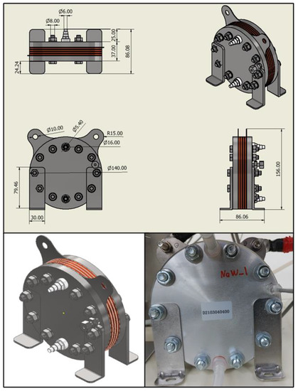
Figure 1.
300 W class PEM water electrolysis stack used in the experimental apparatus.

Table 1.
Specifications of the PEM electrolyzer.
A schematic diagram of a 300 W-class PEM water electrolysis system is shown in Figure 2. The balance of the plant for operating the PEMWE stack consisted of a DC power supply, reservoir, water pump, water trap, heat exchangers, mass flow meters (MFCs), and a cooling water circulation system. Deionized water was stored in the reservoir and refilled from the outside. The pump circulates water, which is slowly heated to the stack’s working temperature of 45 °C using a 3 kW-class electric heater placed in the reservoir. When the stack temperature reaches the operational temperature, the current is provided via a DC power supply. Deionized water is consumed in the PEMWE stack, and an electrochemical reaction generates hydrogen at the cathode and oxygen at the anode. The water discharged from the anode output is sent to the heat exchanger and cooled before returning to the reservoir. The oxygen produced in the stack is dumped in the water trap via the top pipe of the reservoir. In addition, hydrogen is fed to the water trap and heat exchanger to remove moisture and then released out of the system by a mass flow meter. The cooling system circulates the cooling water supplied to the cold side of each heat exchanger to maintain it at 16 °C. The ion conductivity meter mounted at the head of the stack serves as a reference value for estimating the replacement time and monitoring the water quality of the deionized water circulating inside the system.
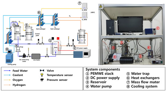
Figure 2.
Schematic diagram and experimental device of 300 W PEMWE system.
3. Model Description
3.1. PEMWE Stack
The physical PEMWE stack model mainly consists of an electrochemical reaction and auxiliary models, such as anode, cathode, membrane, and thermal management systems. Redox reactions (reduction and oxidation) occur during MEA. On the anode side, feed water is split into oxygen, protons, and electrons by oxidation as shown in Equation (1). On the cathode side, hydrogen protons passing through the membrane gain electrons by reduction, as shown in Equation (2). The overall redox reactions are presented in Equation (3) [36].
3.1.1. Anode Model
The anode model calculated the mole flow rates of oxygen and water and their partial pressure. Electrochemically, redox reactions are related to the movement of electrons between species, and water cracking and oxygen evolution reactions occur at the anode [37]. The oxygen generated by Faraday’s law is discharged from the stack. In addition, water moves over the PEM membrane to the cathode via electroosmotic drag and diffusion. The equations related to the mass and species conservation of the water and oxygen generated at the anode are expressed as follows:
where and are the mole flow rates of the water inlet and outlet in the anode; and are the water consumed by the electrochemical reaction and the amount of water delivered to the cathode by diffusion and electroosmotic drag, respectively. are the mole flow rates of the oxygen inlet and outlet on the anode side and the molar flow of oxygen generated, respectively, expressed by Faraday’s law as follows:
The molar flow rate per unit area of the anode is the same as the molar flow rate of water consumed by the electrochemical reaction and the molar flow rate of water moved by diffusion and electroosmotic pressure divided by the activation area of the stack, as follows:
3.1.2. Cathode Model
In the cathode model, hydrogen evolves, water flows, and their partial pressures are calculated [38]. According to Faraday’s law, hydrogen gas is generated on the electrode surface of the cathode. The amount of water discharged from the cathode is the amount of water moving from the anode to the cathode through the membrane by electroosmotic drag and diffusion. The equations related to the conservation of mass and species of water and hydrogen generated at the cathode are expressed as follows:
where , , and are the mole flow rates of the hydrogen inlet and outlet and the hydrogen production by the electrochemical reaction, respectively. are the mole flow rates of water by diffusion and electroosmotic drag, respectively. The mole flow rate of hydrogen generated is expressed by Faraday’s law as follows:
The molar flow rate of water per unit area passing through the cathode is the same as the sum of the molar flow rate of water consumed by the electrochemical reaction and the molar flow rate of water moved by diffusion and electroosmotic drag divided by the activation area of the stack, as follows:
3.1.3. Membrane Model
In the PEMWE stack, as an electrolyte of a water–electrolyte stack, a Nafion®-based polymer electrolyte membrane is generally used, and the anode and cathode are physically separated [39].
The ion conductivity of the polymer electrolyte membrane significantly influences the water electrolysis performance, which causes an electrochemical reaction. The main factor that determines ion conductivity is the amount of water contained in the membrane, and the water content of the membrane is determined by the concentration of water in the anode and the electroosmotic drag. In water electrolysis, the anode side has a high concentration owing to the liquid water; therefore, diffusion occurs from the anode to the cathode. During the electrochemical reaction, hydrogen ions are transferred from the anode to the cathode with water molecules by a process called electroosmotic drag. The molar flow rate of water transferred by electroosmotic drag is as follows:
Here, is the mole flow rate of water transferred by electroosmotic drag, is the electric-osmotic drag coefficient [], which is calculated as follows:
The mole flow rate of water diffused by the difference in water concentration between the anode and cathode is calculated as follows [28]:
where , and are the molar flow rate of water transferred by diffusion, the diffusion coefficient, the membrane thickness, and the concentration in both the anode and cathode, respectively. The diffusion coefficient, , is calculated as follows [38]:
where is the water content of the membrane. Generally, in the PEMWE system, the water content is selected from 21 to 22 because the anode contacts liquid water. The water concentrations of both the anode and cathode were calculated using the following equations [40]:
where is the effective binary diffusion coefficient of the water and oxygen at the anode. is the effective binary diffusion coefficient of water and hydrogen at the cathode. and are the concentrations of water in both the anode and cathode and can be expressed as follows:
3.1.4. Electrochemical Model
The operating cell voltage of a typical water electrolyzer is calculated as the sum of the open-circuit voltage and the voltage losses, which is expressed as follows [41]:
where are the open-circuit voltage, activation loss, and ohmic loss.
Open-Circuit Voltage
The open-circuit voltage represents the voltage when the stack operates in a reversible condition, and it can be expressed as follows [42]:
where is the temperature-dependent reversible cell voltage at the standard temperature and pressure; is the partial pressure of each gas species; and is the water activity, which expresses the quality of the saturated mixture.
Activation Overpotential
The activation overpotential is the loss that activates an electrochemical reaction and represents the reaction rate on the electrode surface [43].
where are the transfer coefficients of the anode and cathode, respectively, and is the exchange current density.
Ohmic Overpotential
Ohmic overpotential is the voltage loss caused by the resistance of the components constituting the stack. Among the components, only two were considered resistant because the resistances of the membrane, anode, and cathode current collector plates were dominant.
where are the resistances of the membrane, anode and cathode, respectively. The resistance of the membrane, , is expressed as follows:
where is the thickness of the membrane and is the electrical conductivity of the membrane.
where is the water content between (21) and (22).
where are the anodic current collector thickness, cathodic current collector thickness, and electronic conductivities of the anode and cathode, respectively, and the values are 1.4 mm, 235 µm, 13,700 S/m, and 46 S/m.
3.2. Thermal Management Model
The thermal management model of the stack is important for determining the dynamic characteristics of the developed PEM water electrolysis system model. The boundary conditions of the system were considered in consideration of the actual stack, and the physical properties of the stack were considered as those of graphite, the most dominant material among the materials constituting the stack. The stack temperature was calculated by considering the sum of the amount of heat generated and lost from the stack, which is expressed as follows:
where , , and are the heat generation of the stack, convection heat loss, and cooling loss by the feed water, respectively. For the stack heat generation, , the cell voltage, number of cells, and stack current are considered.
where is the number of cells, is the operating stack voltage, and is the thermoneutral voltage. The heat released by natural convection is expressed as follows:
where , , and are the heat-transfer coefficient, cell active area, and ambient temperature, respectively.
3.3. Balance of Plant Model
3.3.1. Water Pump Model
The pump model expresses the change in water flow rate according to the operating voltage applied to the pump as an empirical relationship.
where is the mass flow rate of the pump, and is the operating voltage.
3.3.2. Reservoir Model
The reservoir model that regulates the temperature and flow rate of water supplied to the stack is an important model for establishing the system temperature dynamics by controlling the operating temperature of the stack. The boundary conditions of the reservoir model were calculated based on the actual reservoir, and the total amount of water stored in the reservoir, was assumed to be 4.7 kg. In addition, a heater was installed in the reservoir to maintain the outlet temperature of the stack.
where is the reservoir temperature and is the specific heat of the water.
3.3.3. Simple Heat Exchanger Model
The heat exchanger was used to cool down the water discharged from the stack and recovered to the reservoir to compensate for the change in the outlet temperature of the reservoir according to the load of the stack. In this study, the heat exchanger model was simplified to a level at which only the amount of heat exchange could be calculated.
Here, is the specific heat of water because the operating fluid is water.
4. Model Validation
4.1. Model Verification with Experiment Data
The model developed in this study was validated by comparing the simulation results with experimental data. The experimental data for the PEWE were obtained from our PEWE system equipment, as shown in Figure 2. First, the polarization curve was compared with an empirically observed polarization curve to confirm the steady state of the model. Second, the developed simulation model was validated using experimental data while subjecting dynamic reactions to load variations. The simulation was carried out using the NFEC-2021-01-267120GPU Workstation (GPU Workstation/DGX Station, NVIDIA) of the Future Automotive Intelligent Electronics Core Technology Center.
4.2. Verification of Stack Model under Steady State
Figure 3 shows the validation results of the PEMWE electrochemical model obtained by comparing the I–V polarization curve with the experimental data. The experiment was performed at 45 °C under atmospheric pressure. The working temperature of the stack was substantially lower than the commonly accepted operating temperature of 80 °C. However, because the maximum working temperature was 45 °C, the experiment was performed within that range to verify the durability of the manufacturing process. When the current density exceeded 0.1 A/cm2, the simulation curve agreed with the experimental curve within 5% of the error (R2 = 0.9767). Because water electrolysis operates at 0.3 A/cm2 or higher in actual operation, this verification result is feasible under steady-state conditions.
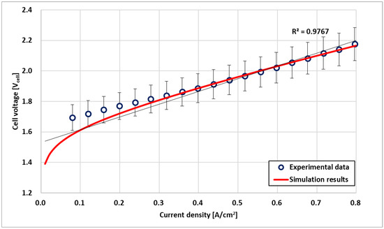
Figure 3.
Electrochemical model validation based on experimental data.
4.3. Verification of Stack Model under Dynamic Condition
A PEM water electrolysis simulation was performed while applying a step load change to the stack to validate the transient characteristics of the stack temperature. The load change of the PEMWE stack influences the operation of the BOP for running the water electrolysis stack and hence, the stack’s operating voltage. In particular, when the temperature of the stack changes because of load variations, the output of the heater changes, which significantly affects the efficiency of the entire system. The step-load variation in the water electrolysis stack is shown in Figure 4. The step load assumed that the PEM stack was supplied with current up to the operating current. Each step load was maintained for 30 min, and the current was initially maintained at 40 A, then rapidly decreased to 20 A in the second step, increased to 30 A in the third step, then decreased to 10 A.
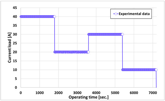
Figure 4.
Current load profile of the dynamic condition.
Figure 5 shows the transient responses of the inlet (a) and outlet (b) temperatures of the water supplied to the stack. For both temperature transient responses, the simulation result values were less variable than the experimental data, and they stabilized quickly. This was due to the difference between the actual experimental environment, the simulation environment, and the controller. However, a comparison of the simulation and the experimental results shows that the temperature tendency is sufficiently followed despite the rapid change in the current, which shows that the simulation model is reliable.
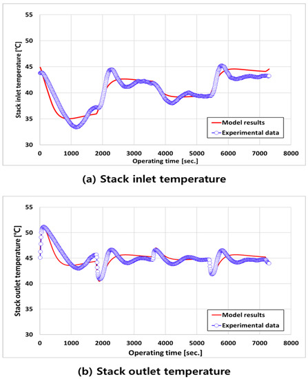
Figure 5.
Temperature transient response of (a) stack inlet and (b) outlet by current load change.
Figure 6 shows a comparison of the experimental and simulation results on the transient response of the voltage to the current load change in Figure 5. For the current load profile, the voltage transient response of the stack stabilized faster than the experimental data. The performance of the stack depends on the operating temperature of the stack, and as can be observed in Figure 6, the temperature stabilizes the simulation faster than the experiment, resulting in the rapid stabilization of the voltage transient response.
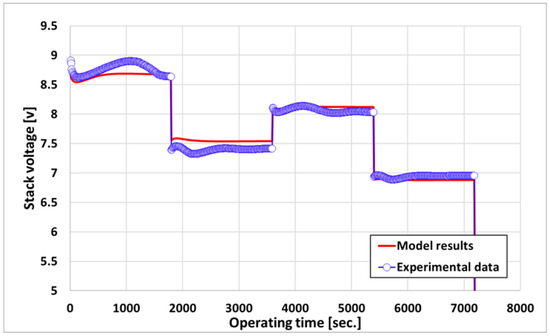
Figure 6.
Voltage transient response by current load change.
5. PEMWE HILS System
5.1. Need for HILS
The hardware-in-the-loop simulation (HILS) provides an environment where research and testing can be conducted efficiently and reliably in the trade-off between cost, time, and accuracy. The HILS, which connects the input and output of hardware and models for verification and testing and simulates them, is a suitable method for studying water electrolysis stacks that do not have durability at the system level. In this study, the HILS was applied as a method to analyze and understand the PEMWE system and diagnose the failure of the system by linking the high-resolution and feasibility simulation model with the hardware.
5.2. Hardware-in-the-Loop Simulation Interface
The host PC (controller) and target PC (RT-PC) communication and signal flow were designed for interface and I/O verification. The host PC development environment was set to Matlab/Simulink®, where the water electrolysis system was developed, and the real-time controller, the target PC, was set to PXI. For communication between the host PC and target PC, NI Veristand was set up, which is a program that can link LabVIEW, a development environment of NI, and Simulink, a development environment of Mathworks. Veristand can use the Dynamic Link Library to retrieve input and output information for models built in Simulink, and Ethernet communication can be used to form a network between the input and output information loaded on Veristand to enable communication. Table 2 lists the compatibility settings for the networking. Figure 7 shows a schematic of the communication and equipment signal flow designed in this study.
Table 2.
Compatibility settings for HILS.
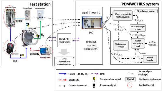
Figure 7.
Signal flow chart of the PEMWE HILS system.
5.3. HILS-Based Fault Detection
Figure 8 shows the failure-detection algorithm of the PEMWE system using HILS. The transient response results of the system generated by the validated dynamic characteristic model follow the response well, even in an operating state where no failure has occurred in the experimental device. It is reasonable to expect the failures in the experimental results to exhibit an obvious difference from the transient response of the dynamic characteristic model results [44]. The system control signal (u) is input to the experimental device and simulation model simultaneously, and the residual can be analyzed by comparing the experimental results (y) and simulation results (y′). Because simulations always work ideally, if the system is in a normal state, the residual approaches 0, and in case of a failure, the residual deviates from 0 using the residual of the output result value of the actual hardware and the PEM electrolytic HILS system. Thus, it is possible to detect the failure of an actual experimental device in real-time.
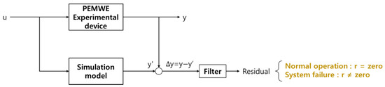
Figure 8.
Fault-detection algorithm.
6. Results and Discussion
6.1. PEMWE HILS System Validation
The developed PEMWE HILS system was verified before applying the failure-detection algorithm. Figure 9 shows the current profile used to measure the transient response to the system load change. The current profile is divided into a step-load section to measure the transient response to a gradual load change of a water electrolytic system and a dynamic-load section to measure the transient response to a sudden load change in the system. The step-load section was measured by gradually increasing the supply current of the stack by 4 A, and the dynamic-load section was measured by varying the supply current of the stack from 40 A to 20 A.
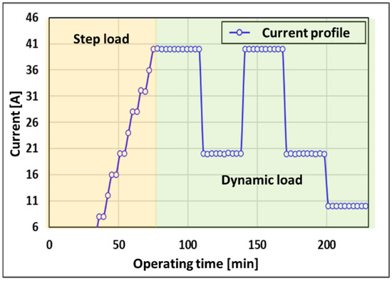
Figure 9.
Current profile for the HILS system.
6.2. PEMWE HILS System Results
Figure 10 compares the transient response between the HILS system and experimental setup. Figure 10a,b illustrates the transient response of the voltage and the transient response of the temperature at the stack input/output, respectively, as the current change is supplied to the stack. The result of the HILS stabilizes faster than the experimental setup because the difference in the controller and the unmeasurable heat loss that occurs in the experimental setup are not considered.
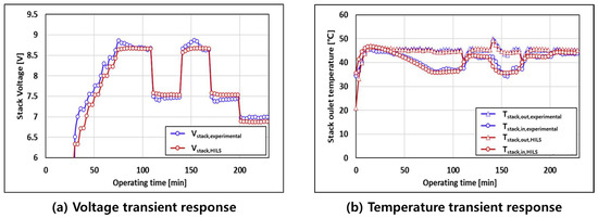
Figure 10.
Comparison of transient responses between the HILS system and experimental setup.
Figure 11 shows the transient response and error of the stack inlet temperature of the HILS system and the experiment in the dynamic-load section. In the area highlighted in red in Figure 11, the error of the residuals of the HILS system and the experimental setup varies within 10% in the dynamic-load section, where the current supplied to the stack increases rapidly from 20 A to 40 A.
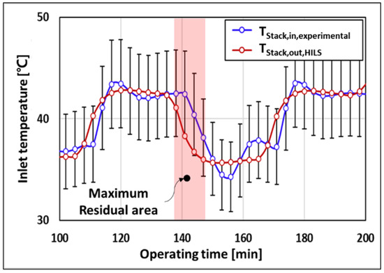
Figure 11.
Temperature transient responses of stack inlet.
6.3. HILS-Based Fault-Detection System
The failure-detection algorithm in Section 5.3 was applied to the PEMWE HILS system developed in Section 6.1 and Section 6.2 to diagnose the state of the water electrolytic system and detect the failure. Figure 12 shows the GUI of the fault-detection system developed based on the PEMWE HILS system. To detect the failure of the detection system, the system was observed after the heater was forcibly shut down after the experimental device was stabilized in a normal state. Ten minutes after the heater was stopped, the failure-detection system began to detect the abnormal operation of the system. This is caused by heat loss that cannot be measured in the controller and the device of the HILS system.
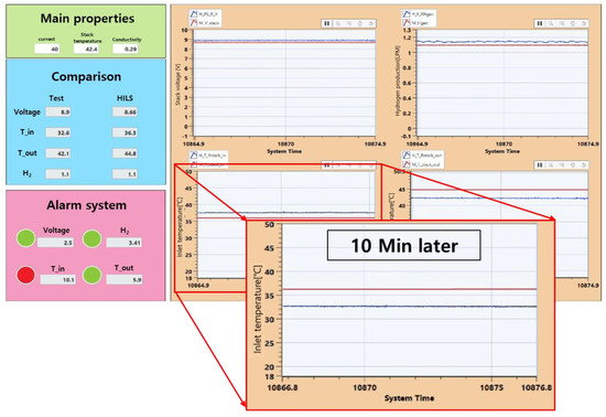
Figure 12.
GUI of HILS-based fault-detection system.
7. Conclusions
Diagnosis of the initial fault is necessary to ensure the reliability of the PEM water electrolysis system. A water electrolysis system is a complex system that includes a stack and several subsystems, such as pumps, heaters, and cooling systems, that maintain the operating conditions of the stack. In this study, a mathematical model was developed to simulate the dynamic characteristics of a water electrolysis system, and an HILS system was constructed to propose a model-based fault diagnosis.
- Mathematical models of stacks and BOPs were developed for the fault diagnosis of water electrolysis systems and verified based on experimental results. Compared with the experimental results, the verified model was confirmed to operate correctly within an error magnitude of 10%.
- To diagnose the real-time failure of the water electrolysis system, an HILS system was applied in which the experimental device and the simulation model were operated in real-time. To detect errors in the system, we propose a method of detection by comparing the voltage of the stack and the experimental results obtained through thermocouples installed at the front and rear ends of the stack in real-time. Faults were detected 10 min after the occurrence. This is considered to be caused by the complexity of the model and the real-time delay.
- In a further study, AI-based learning models will be developed, and research that can be applied in real-time will be conducted. This will increase the reliability of the water electrolysis system and help its commercialization.
Author Contributions
All the authors contributed to this research. T.K.: model design, methodology, software, writing—original draft, and stack performance evaluation. R.K.: investigation and experimental design. D.H.: establishment of a stack performance evaluation protocol and writing—modification draft. J.H.: supervision, writing—modification draft and writing—review and editing. All authors have read and agreed to the published version of the manuscript.
Funding
This study was supported by “Regional Innovation Strategy (RIS)” through the National Research Foundation of Korea (NRF) funded by the Ministry of Education (MOE) (2021RIS-004) and the Korea Electrotechnology Research Institute (KERI) Primary Research Program through the National Research Council of Science & Technology (NST) funded by the Ministry of Science and ICT (MSIT) (No. 23A01043).
Data Availability Statement
Not applicable.
Conflicts of Interest
The authors declare no conflict of interest.
Nomenclature
| Symbol | |
| A | Active area (cm2) |
| an | Anode |
| C | Concentration |
| C | Specific heat |
| ca | Cathode |
| D | Diffusion coefficient |
| F | Faraday constant |
| I | Current |
| I | Current density (A/cm2) |
| m | Mass flow rate |
| MFC | Mass flow meter |
| N | Molar flow rate |
| n | Number of cells, molar flow rate per unit area |
| P | Pressure |
| PEM | Proton exchange membrane |
| Q | Heat transfer |
| R | Resistance |
| RV | Reservoir |
| T | Temperature |
| V | Stack voltage |
| WE | Water electrolysis |
| Greek Symbols | |
| Water content of the membrane | |
| Transfer coefficient | |
| Thickness | |
| Density | |
| Electrical conductivity | |
| Subscripts | |
| Hydrogen | |
| Water | |
| Oxygen | |
| 0 | Stand condition, exchanger current density (activation overpotential) |
| act | Activation loss |
| ch | Channel |
| el | Electrode |
| mem | Membrane |
| OCV | Open-circuit voltage |
| ohmic | Ohmic loss |
| x | Gas species of partial pressure |
| Oxygen | |
| Superscripts | |
| Time rate | |
| Consumption | |
| Diffusion | |
| Electroosmotic drag | |
| Generation | |
| Inlet | |
| Outlet | |
References
- Bilgen, S.; Keleş, S.; Kaygusuz, A.; Sarı, A.; Kaygusuz, K. Global warming and renewable energy sources for sustainable development: A case study in Turkey. Renew. Sustain. Energy Rev. 2008, 12, 372–396. [Google Scholar] [CrossRef]
- Tafavogh, M.; Zahedi, A. Design and production of a novel encapsulated nano phase change materials to improve thermal efficiency of a quintuple renewable geothermal/hydro/biomass/solar/wind hybrid system. Renew. Energy 2021, 169, 358–378. [Google Scholar] [CrossRef]
- Feng, Q.; Yuan, X.; Liu, G.; Wei, B.; Zhang, Z.; Li, H.; Wang, H. A review of proton exchange membrane water electrolysis on degradation mechanisms and mitigation strategies. J. Power Sources 2017, 366, 33–55. [Google Scholar] [CrossRef]
- Scheepers, F.; Stähler, M.; Stähler, A.; Rauls, E.; Müller, M.; Carmo, M.; Lehnert, W. Temperature optimization for improving polymer electrolyte membrane-water electrolysis system efficiency. Appl. Energy 2021, 283, 116270. [Google Scholar] [CrossRef]
- Muradov, N.Z. How to produce hydrogen from fossil fuels without CO2 emission. Int. J. Hydrog. Energy 1993, 18, 211–215. [Google Scholar] [CrossRef]
- Mazloomi, S.K.; Sulaiman, N. Influencing factors of water electrolysis electrical efficiency. Renew. Sustain. Energy Rev. 2012, 16, 4257–4263. [Google Scholar] [CrossRef]
- Rashid, M.D.; Al Mesfer, M.K.; Naseem, H.; Danish, M. Hydrogen Production by Water electrolysis: A review of Alkaline Water electrolysis, PEM water Electrolysis and High Temperature Water Electrolysis. Int. J. Eng. Adv. Technol. 2015, 4, 2249. [Google Scholar]
- Shiva Kumar, S.; Himabindu, V. Hydrogen production by PEM water electrolysis—A review. Mater. Sci. Energy Technol. 2019, 2, 442–454. [Google Scholar] [CrossRef]
- Frano, B. PEM electrolysis for production of hydrogen from renewable energy sources. Sol. Energy 2005, 75, 661–669. [Google Scholar]
- Frensch, S.H.; Fouda-Onana, F.; Serre, G.; Thoby, D.; Araya, S.S.; Kær, S.K. Influence of the operation mode on PEM water electrolysis degradation. Int. J. Hydrog. Energy 2019, 44, 29889–29898. [Google Scholar] [CrossRef]
- Chandesris, M.; Medeau, V.; Guillet, N.; Chelghoum, S.; Thoby, D.; Fouda-Onana, F. Membrane degradation in PEM water electrolyzer: Numerical modeling and experimental evidence of the influence of temperature and current density. Int. J. Hydrog. Energy 2015, 40, 1353–1366. [Google Scholar] [CrossRef]
- Schalenbach, M.; Carmo, M.; Fritz, D.L.; Mergel, J.; Stolten, D. Pressurized PEM water electrolysis: Efficiency and gas crossover. Int. J. Hydrog. Energy 2013, 38, 14921–14933. [Google Scholar] [CrossRef]
- Selamet, Ö.F.; Becerikli, F.; Mat, M.D.; Kaplan, Y. Development and testing of a highly efficient proton exchange membrane (PEM) electrolyzer stack. Int. J. Hydrog. Energy 2011, 36, 11480–11487. [Google Scholar] [CrossRef]
- Millet, P.; Ngameni, R.; Grigoriev, S.A.; Mbemba, N.; Brisset, F.; Ranjbari, A.; Etiévant, C. PEM water electrolyzers: From electrocatalysis to stack development. Int. J. Hydrog. Energy 2010, 35, 5043–5052. [Google Scholar] [CrossRef]
- Hughes, J.P.; Clipsham, J.; Chavushoglu, H.; Rowley-Neale, S.J.; Banks, C.E. Polymer electrolyte electrolysis: A review of the activity and stability of non-precious metal hydrogen evolution reaction and oxygen evolution reaction catalysts. Renew. Sustain. Energy Rev. 2021, 139, 110709. [Google Scholar] [CrossRef]
- Babic, U.; Suermann, M.; Büchi, F.N.; Gubler, L.; Schmidt, T.J. Critical review-identifying critical gaps for polymer electrolyte water electrolysis development. J. Electrochem. Soc. 2017, 164, F387–F399. [Google Scholar] [CrossRef]
- Lee, C.-Y.; Chen, C.-H.; Li, S.-C.; Wang, Y.-S. Development and application of flexible integrated microsensor as real-time monitoring tool in proton exchange membrane water electrolyzer. Renew. Energy 2019, 143, 906–914. [Google Scholar] [CrossRef]
- Stempien, J.P.; Sun, Q.; Chan, S.H. Solid oxide electrolyzer cell modeling: A review. J. Power Technol. 2013, 93, 216–246. [Google Scholar]
- Ruuskanen, V.; Koponen, J.; Sillanpää, T.; Huoman, K.; Kosonen, A.; Niemelä, M.; Ahola, J. Design and implementation of a power-hardware-in-loop simulator for water electrolysis emulation. Renew. Energy 2018, 119, 106–115. [Google Scholar] [CrossRef]
- Fallisch, A.; Schellhase, L.; Fresko, J.; Zechmeister, M.; Zedda, M.; Ohlmann, J.; Zielke, L.; Paust, N.; Smolinka, T. Investigation on PEM water electrolysis cell design and components for a HyCon solar hydrogen generator. Int. J. Hydrog. Energy 2017, 42, 13544–13553. [Google Scholar] [CrossRef]
- Khelfaoui, N.; Djafour, A.; Ghenai, C.; Laib, I.; Danoune, M.B.; Gougui, A. Experimental investigation of solar hydrogen production PV/PEM electrolyser performance in the Algerian Sahara regions. Int. J. Hydrog. Energy 2021, 46, 30524–30538. [Google Scholar] [CrossRef]
- Hernández-Gómez, Á.; Ramirez, V.; Guilbert, D.; Saldivar, B. Cell voltage static-dynamic modeling of a PEM electrolyzer based on adaptive parameters: Development and experimental validation. Renew. Energy 2021, 163, 1508–1522. [Google Scholar] [CrossRef]
- Millet, P.; Mbemba, N.; Grigoriev, S.A.; Fateev, V.N.; Aukauloo, A.; Etiévant, C. Electrochemical performances of PEM water electrolysis cells and perspectives. Int. J. Hydrog. Energy 2011, 36, 4134–4142. [Google Scholar] [CrossRef]
- Corengia, M.; Torres, A.I. Two-phase dynamic model for pem electrolyzer. In Proceedings of the 13th International Symposium on Process Systems Engineering, San Diego, CA, USA, 1–5 July 2018; Volume 44, pp. 1435–1440. [Google Scholar]
- Nie, J.; Chen, Y.; Cohen, S.; Carter, B.D.; Boehm, R.F. Numerical and experimental study of three-dimensional fluid flow in the bipolar plate of a PEM electrolysis cell. Int. J. Therm. Sci. 2009, 48, 1914–1922. [Google Scholar] [CrossRef]
- Sharifian, S.; Asasian Kolur, N.A.; Harasek, M. Transient simulation and modeling of photovoltaic-PEM water electrolysis. Energy Sources 2020, 42, 1097–1107. [Google Scholar] [CrossRef]
- Görgün, H. Dynamic modelling of a proton exchange membrane (PEM) electrolyzer. Int. J. Hydrog. Energy 2006, 31, 29–38. [Google Scholar] [CrossRef]
- Abdin, Z.; Webb, C.J.; Gray, E.M. Modelling and simulation of a proton exchange membrane (PEM) electrolyser cell. Int. J. Hydrog. Energy 2015, 40, 13243–13257. [Google Scholar] [CrossRef]
- Guilbert, D.; Vitale, G. Experimental validation of an equivalent dynamic electrical model for a proton exchange membrane electrolyzer. In Proceedings of the IEEE International Conference on Environment and Electrical Engineering, Palermo, Italy, 12–15 June 2018; Volume 2018. [Google Scholar] [CrossRef]
- Zhang, S.; Yuan, X.; Wang, H.; Merida, W.; Zhu, H.; Shen, J.; Wu, S.; Zhang, J. A review of accelerated stress tests of MEA durability in PEM fuel cells. Int. J. Hydrog. Energy 2009, 34, 388–404. [Google Scholar] [CrossRef]
- Lebbal, M.E.; Lecœuche, S. Identification and monitoring of a PEM electrolyser based on dynamical modelling. Int. J. Hydrog. Energy 2009, 34, 5992–5999. [Google Scholar] [CrossRef]
- Park, J.Y.; Lim, I.S.; Choi, E.J.; Kim, M.S. Fault diagnosis of thermal management system in a polymer electrolyte membrane fuel cell. Energy 2021, 214, 119062. [Google Scholar] [CrossRef]
- Oh, H.Y.; Lee, W.Y.; Won, J.Y.; Kim, M.J.; Choi, Y.Y.; Han, S.B. Residual-based fault diagnosis for thermal management systems of proton exchange membrane fuel cells. Appl. Energy 2020, 277, 115568. [Google Scholar] [CrossRef]
- Zhou, S.; Lu, Y.; Bao, D. Fault diagnosis of PEMFC systems based on an auxiliary transfer network. Int. J. Hydrog. Energy 2023. [Google Scholar] [CrossRef]
- Sheng, Y.; Du, D.; Xia, A.; Mao, Z. Actuator fault detection for a PEMFC system based on delta operator approach. Int. J. Hydrog. Energy 2022, 47, 29148–29161. [Google Scholar] [CrossRef]
- Hassan, A.H.; Liao, Z.; Wang, K.; Abdelsamie, M.M.; Xu, C.; Wang, Y. Exergy and Exrgoeconimic Analysis for the proton Exchange Membrane water Electrolysis under Varioius Operationg Conditions and Design Parameters. Energies 2022, 15, 8247. [Google Scholar] [CrossRef]
- Hernández-Gómez, Á.; Ramirez, V.; Guilbert, D.; Saldivar, B. Development of an adaptive static-dynamic electrical model based on input electrical energy for pem water electrolysis. Int. J. Hydrog. Energy 2020, 45, 18817–18830. [Google Scholar] [CrossRef]
- Yigit, T.; Selamet, O.F. Mathematical modeling and dynamic Simulink simulation of high-pressure PEM electrolyzer system. Int. J. Hydrog. Energy 2016, 41, 13901–13914. [Google Scholar] [CrossRef]
- Ito, H.; Maeda, T.; Nakano, A.; Takenaka, H. Properties of nafion membranes under PEM water electrolysis conditions. Int. J. Hydrog. Energy 2011, 36, 10527–10540. [Google Scholar] [CrossRef]
- Marangio, F.; Santarelli, M.; Cali, M. Theoretical model and experimental analysis of a high pressure PEM water electrolyser for hydrogen production. Int. J. Hydrog. Energy 2009, 34, 1143–1158. [Google Scholar] [CrossRef]
- García-Valverde, R.; Espinosa, N.; Urbina, A. Simple PEM water electrolyser model and experimental validation. Int. J. Hydrog. Energy 2012, 37, 1927–1938. [Google Scholar] [CrossRef]
- Choi, P.; Bessarabov, D.G.; Datta, R. A simple model for solid polymer electrolyte (SPE) water electrolysis. Solid Sate Ion. 2004, 175, 535–539. [Google Scholar] [CrossRef]
- Falcão, D.S.; Pinto, A.M.F.R. A review on PEM electrolyzer modeling: Guidelines for beginners. J. Clean. Prod. 2020, 261, 121184. [Google Scholar] [CrossRef]
- Kheirrouz, M.; Melino, F.; Ancona, M.A. Fault detection and diagnosis methods for green hydrogen production: A review. Int. J. Hydrog. Energy 2022, 47, 27747–27774. [Google Scholar] [CrossRef]
Disclaimer/Publisher’s Note: The statements, opinions and data contained in all publications are solely those of the individual author(s) and contributor(s) and not of MDPI and/or the editor(s). MDPI and/or the editor(s) disclaim responsibility for any injury to people or property resulting from any ideas, methods, instructions or products referred to in the content. |
© 2023 by the authors. Licensee MDPI, Basel, Switzerland. This article is an open access article distributed under the terms and conditions of the Creative Commons Attribution (CC BY) license (https://creativecommons.org/licenses/by/4.0/).