Abstract
This paper presents an analysis and simulation of the mathematical model associated to the DC/DC Boost converter–full-bridge Buck inverter system to regulate the voltage output of the DC/DC Boost converter allowing bipolar voltages higher than the input voltage via the full-bridge Buck inverter. To validate the model, the differential flatness property is applied via the flat outputs of the system (energy for the DC/DC Boost converter and the voltage of the full-bridge Buck inverter) considering the complete dynamics, in conjunction with fixed and time-variant trajectory planning. In the simulation results, it is observed that the error signals of the states versus the reference trajectories are acceptable. Regarding the validation of the model, this is performed with open-loop simulations at the circuit level using the SimPowerSystems Toolbox of Matlab-Simulink. The simulation results validate the good performance of the system under study. In this way, the main contribution of this work is that for the first time in the literature, the analysis of a complete dynamics for a conversion system from DC to AC without the use of a transformer and taking advantage of differential flatness is reported; thus, the system analyzed could be represented as an alternative in applications of renewable energies that require conversion from DC to AC.
1. Introduction
DC/DC power converters are electronic circuits associated with the conversion, control, and conditioning of electrical energy. The conversion from DC to AC using such converters constitutes a sub-area in the field of power electronics. Therefore, the conversion is widely used in various industrial applications including uninterruptible power supplies [1,2,3], AC motor drivers [4,5,6], and others, such as renewable energies [7,8,9].
In relation to renewable energies, many research works have reported the use of the full-bridge Buck converter topology [10,11,12,13,14,15,16,17,18,19], Boost converter [20,21,22], and Buck-Boost [23,24,25]. On the other hand, the concept of differential flatness comes from differential algebra for dynamic and control systems. Differential flatness has been studied in various fields of engineering such as robotics; control processes; aerospace systems; optimization systems; and trajectory planning in linear, nonlinear, and infinite dimensional systems described by delay differential systems and controlled partial differential equations with boundary conditions [26]. The main feature of differentially flat systems is that the input and state variables can be rewritten in terms of a set of variables, known as flat outputs, and a finite number of their successive derivatives without integrating the underlying differential equation. In this direction, the works that report the use of differential flatness focus on DC/DC converters; for example, in [27], the authors report a control method for Maximum Power Point Tracking (MPPT) based on the differential flatness property of the DC/DC Boost converter. The approach uses a classical trajectory tracking control based on differential flatness, defining a reference voltage in terms of the maximum power provided by the PV panel. Similarly, in [28], the authors present the design of a control method for the voltage regulation and trajectory tracking tasks of a DC/DC Boost converter via the energy stored by the converter; the proposed approach exploits the differential flatness property of the system. On the other hand, regarding DC/DC converters as driver for DC motors for the unidirectional angular velocity tracking task the following work are described, for example in [29] the authors reported a system of a Buck converter that feeding a DC motor, with the purpose of solving the angular velocity tracking task, the authors have designed a two-level hierarchical control based on sliding-PI modes for the Buck converter and differential flatness for the DC motor, being the flat output the voltage and the angular velocity of the Buck converter and DC motor, respectively. The authors in [30] used a recursive approach in which the differential flatness properties are applied to synthesize a controller that guarantees the closed-loop asymptotic stability of a Buck converter connected to a DC motor. In [31] they propose a two-level hierarchical control for a DC motor powered by a Cuk converter, the control is divided into two parts: the first one associated with the mathematical model of the DC motor to design a robust control by using the differential flatness property for tracking angular velocity trajectories, the second part was the independent control, based on cascaded sliding-PI modes for the Cuk converter which allows the converter output voltage to follow the specific voltage trajectory. Related to DC/DC converters as a driver for DC motors for the bidirectional angular velocity task and concerning the validation of mathematical models through the differential flatness property different research works have been published such as: DC/DC Buck converter-inverter-DC motor system [32], in the DC/DC Buck converter subsystem the flat output is the voltage; the DC/DC Boost converter-inverter-DC motor system [33], the flat output is the energy that stores the DC/DC Boost converter; the “DC/DC Buck-Boost converter-inverter-DC motor” system [34], the DC/DC Buck-Boost converter subsystem energy is the flat output; and, on the other hand in [35], they present the validation of the mathematical model associated with the “full-bridge Buck inverter-DC motor” system, the differential flatness property associated with the mathematical model is exploited for all the system variables. In the works reported in [32,33,34,35] the flat output associated with the DC motor is the angular velocity, among others. In addition, other research works have reported the use of the differential flatness property for the task of bidirectional angular velocity control [36,37,38,39]. For example, in [36], the authors developed a robust hierarchical control for DC/DC Buck-Boost-inverter-DC motor system based on deferential flatness, in [37] was designed a robust control for “MIMO DC/DC Boost converter-inverter-DC motor” system, such robustness is achieved by exploiting the differential flatness related to the system. Also, in [38] is reported a passivity-based control to solve the angular velocity task in the “full-bridge Buck inverter-DC motor” system, the reference trajectories are obtained through the differential flatness exhibited by the system. Finally, in [39] was presented a robust control based on the differential flatness strategy for the “full-bridge Buck inverter-DC motor” system, for the trajectory tracking task. Moreover, full-bridge DC/AC has been widely used in mechatronic energy systems, such as photovoltaic systems, vertical axis wind turbine systems and hybrid electric vehicles, among others. Also, it is important for the operation and efficiency of the use of renewable energy systems and their interconnection with the power grid to ensure operation and overall sustainability. The requirements for high performance DC/AC converter systems are generally based on the following criteria: (1) Output voltage waveform with low total harmonic distortion (THD). (2) Fast transient response in case of sudden load change. (3) Steady state errors should be as small as possible. For instance, in a photovoltaic system, the essential function of the full-bridge DC/AC allows the conversion of a DC voltage produced by the PV array and a sinusoidal AC power output with controllable magnitude and frequency. A single-stage DC/AC converter converts DC to AC without the need for an intermediate stage. A two-stage DC/AC converter is structured by a DC/DC converter plus a DC/AC converter. The first stage DC/DC converter supplies the maximum power processed by the maximum power point tracking algorithm to the second stage DC/AC converter and also regulates the DC voltage. Therefore, whether it is a single-stage or two-stage DC/AC converter, the closed-loop circuit control technology should be employed to produce a high-quality DC/AC converter output voltage even under nonlinear loads. In this direction, with the purpose of solving the assignment of DC to AC conversion via DC/DC power electronic converters, and in conjunction with the use of differential flatness this paper performs the analysis and validation of the DC/DC Boost converter–full-bridge Buck inverter system, which is represented by two-stage DC/AC converter, with stage 1-Boost converter and stage 2-the full-bridge Buck inverter. It is worth considering, on the other hand, that the full-bridge Buck inverter is generally the most used to perform such a conversion; one of the characteristics of this topology is that the output voltage is always lower than the input voltage. When an output voltage higher than the input voltage is required, one option is to couple a step-up transformer to the output of the converter. However, this type of design leads to some drawbacks since the transformer adds dynamics to the system, such as non-linearity of the transformer, resistances, and parasitic currents, among others, causing an increase in the size and weight of the converter circuit. According to [40], a design alternative that does not involve a step-up transformer is to use a DC/DC Boost converter between the DC power supply and the full-bridge Buck inverter. DC/DC Boost converter is widely used in applications where the output voltage must be higher than the input source voltage, however controlling the DC/DC Boost converter presents greater challenges than controlling the DC/DC Buck converter, where the output voltage is lower than the input source voltage. Other problems in controlling the DC/DC Boost converter lie in the fact that it is a non-linear system [27,28], this stems from the fact that it has interconnected state variables, and its input disturbances and/or system parameter variations. DC/DC Boost converters also exhibit the non-minimum phase phenomenon with the output voltage and current having different phase characteristics. The control input appears in both the voltage and current equations and is therefore more difficult to control.
To the best knowledge of the authors—regarding the configuration of a DC/DC Boost converter between a DC power supply and full-bridge Buck inverter—at the moment, only a two-level hierarchical control has been reported by Biel et al. [40]. The authors designed a control for the high level associated with the DC/DC Boost converter, while for the low level associated with the full-bridge Buck inverter they used another control, with both controls based on sliding modes.
Motivation and Contribution
Following the objective of DC to AC conversion presented in [40] and motivated by the differential flatness property used in: DC/DC Boost converters [27,28], DC/DC converters as drivers for DC motors for the unidirectional angular velocity tracking task [29,30,31], validation of mathematical models of DC/DC converter as drivers for DC motors for the bidirectional angular velocity task [32,33,34,35] and controls for the bidirectional angular velocity tracking task via DC/DC power electronic converters [36,37,38,39] and with the goal of obtaining more efficient conversion systems in renewable energy applications the DC/DC Boost converter–full-bridge Buck inverter system is considered as a fundamental part of the analysis in this work. Hence, the contribution of this work is to analyze and validate the mathematical model of the DC/DC Boost converter–full-bridge Buck inverter system under useful time-varying duty cycles considering the complete dynamics of the system and not separately. For this, it relies on the differential flatness property of the system.
2. DC/DC Boost Converter–Full-Bridge Buck Inverter System
In this section, the mathematical model of the DC/DC Boost converter–full-bridge Buck inverter system is presented. In addition, the differential parameterization associated with the model that allows generating the reference trajectories is presented.
2.1. Generalization of the System
In Figure 1, the electronic circuit of the DC/DC Boost converter–full-bridge Buck inverter system is presented, which consists of the following subsystems:
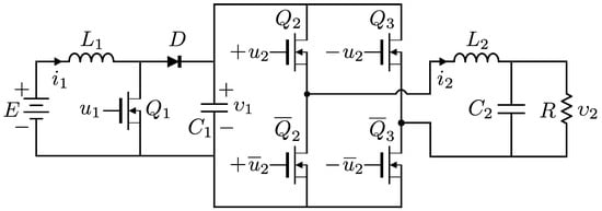
Figure 1.
DC/DC Boost converter–full-bridge Buck inverter system.
- DC/DC Boost converter. E is the power supply, is the input ON/OFF for the transistor , a current flows through the inductor , and D is the diode. is the output voltage of the converter associated to the terminals of the capacitor , and it will be the supply for the full-bridge Buck inverter.
- Full-bridge Buck inverter. Here, and are the inputs that turn ON/OFF the four transistor arrays , , , and , where the functions of , complement , , respectively. In this way, it is possible to invert and modulate the direction of the current flow and the voltage for the low-pass filter circuit with its inductor and capacitor .
The average mathematical model of the DC/DC Boost converter–full-bridge Buck inverter system, according to [40], is described by
where and correspond to the average inputs of the DC/DC Boost converter and the full-bridge Buck inverter, respectively. The other parameters and states (1)–(4) were described previously.
2.2. Generation of Reference Trajectories
In this section, the differential parameterization of the average system ((1)–(4)) is described.
According to [33,41], the flat output of the Boost DC/DC converter is the energy, i.e.,
Meanwhile, (3) and (4) describe the dynamic behavior of the DC/DC Buck converter. According to [42], the flat output for the subsystem (3), (4) is ,
After carrying out the differential parameterization of the system and in terms of the flat output, it results in
with
Note that the new representation of the average system, i.e., (7)–(12), called differential parameterization, has been rewritten in terms of , and its successive derivatives.
After replacing and for and , respectively, in (7)–(12), the reference trajectories are generated, which are , , , , and ; these are determined by
with
where and are the energy of the DC/DC Boost converter and the voltage of the full-bridge Buck inverter, respectively. Thus, in this way, it will be possible to obtain through the simulation the dynamic evolution of the states of the system along with their corresponding reference trajectories .
In Figure 2, a block diagram is shown that represents the system in open loop.
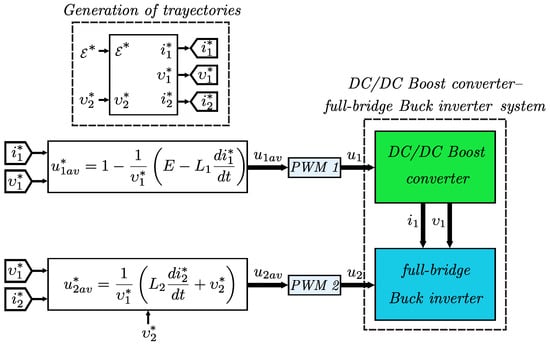
Figure 2.
Block diagram for the DC/DC Boost converter–full-bridge Buck inverter system. In the diagram, and are considered.
3. Simulation Results and Discussion
In this section, the circuit used to simulate and validate the mathematical model of the DC/DC Boost converter–full-bridge Buck inverter system is described.
3.1. Block Diagram and Circuit
In Figure 3, the electronic diagram is presented, which was built in Matlab-Simulink and is described with the following conditions:
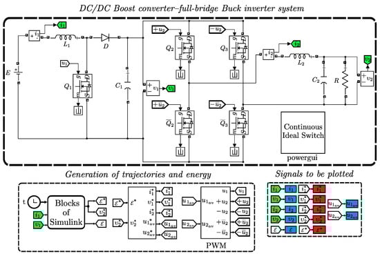
Figure 3.
Circuit diagram for the DC/DC Boost converter–full-bridge Buck inverter system.
- DC/DC Boost converter–full-bridge Buck inverter system. The nominal values associated with the DC/DC Boost converter parameters areIn order to obtain the parameters associated with the DC/DC Boost converter, the design data shown in Table 1 are proposed and the methodology described in [41] is also taken into account; the parameters are listed in Table 1.
 Table 1. Design specifications for the DC/DC Boost converter.The parameter values associated with the full-bridge Buck inverter areThe parameters for the full-bridge Buck inverter are listed in Table 2.
Table 2. Design specifications for the full-bridge Buck inverter.
Table 1. Design specifications for the DC/DC Boost converter.The parameter values associated with the full-bridge Buck inverter areThe parameters for the full-bridge Buck inverter are listed in Table 2.
Table 2. Design specifications for the full-bridge Buck inverter. - Generation of trajectories and energy. In this block, the reference paths are programmed with , , , , and through the desired trajectories and , which are selected by means of the polynomials of Bézier [43], as shown in the following:Bézier Trajectorieswith given bywhere smoothly interpolates between initial and final energy in the time interval .Since energy is not a state of the system, we decide to solve for in terms of ; after this consideration, the relations in equilibrium are obtained: and . Considering the system (1)–(4) in permanent state and solving for , we obtainSimilarly, the reference smoothly interpolates between initial and final voltages in the same time interval; moreover, in this block, the energy is reconstructed through (5). Finally, in relation to the PWM frequency, it is taken at a constant 50 Khz.
3.2. Simulations Analysis
Regarding the simulation, using the electronic diagram built in Matlab-Simulink and described in the previous section, in order to analyze the dynamic evolution of the states of the system together with their corresponding reference trajectories to validate the mathematical model for the DC/DC Boost converter–full-bridge Buck inverter system, the simulation results obtained are presented in this subsection. In Figure 4, Figure 5, Figure 6, Figure 7, Figure 8 and Figure 9, the plots in blue color represent the simulations for the electronic diagram while the results in red color correspond to the reference signals obtained by plotting (24) to (28). The conditions for the simulations are described as follows:
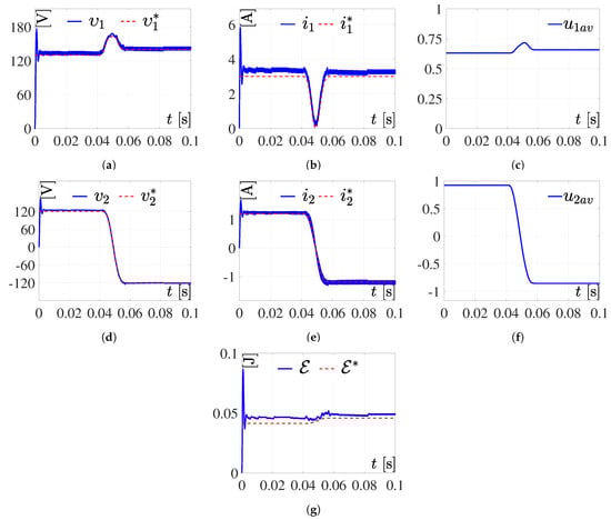
Figure 4.
Simulation 1. Response of the system to (19) and (20) and the parameters defined by (24). (a,b,d,e,g) are the results of the simulation correspond to variables respectively, whereas the results related to the reference variables are . Meanwhile, (c,f) are the inputs of the DC/DC Boost converter and the full-bridge Buck inverter, respectively.
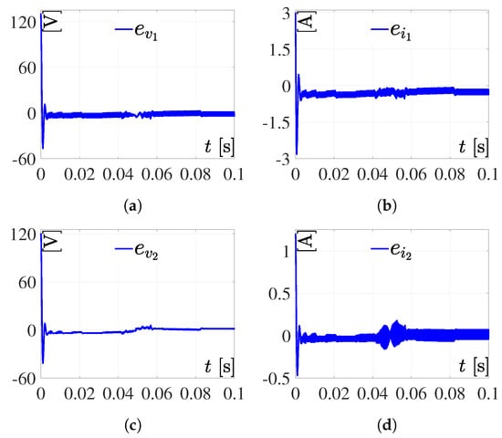
Figure 5.
Tracking errors related with simulation 1. (a) ; (b) ; (c) ; (d) .
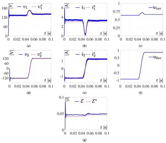
Figure 6.
Simulation 2. Response to the system for (19) and (20) and the parameters defined by (25). (a,b,d,e,g) are the results of the simulation correspond to variables respectively; whereas the results related to the reference variables are . Meanwhile, (c,f) are the inputs of the DC/DC Boost converter and the full-bridge Buck inverter, respectively.
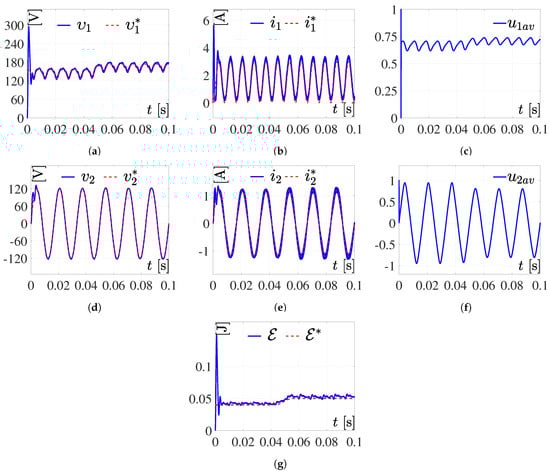
Figure 7.
Simulation 3. Response to the system for (19) and (26). (a,b,d,e,g) are the results of the simulation correspond to variables respectively, whereas the results related to the reference variables are . Meanwhile, (c,f) are the inputs of the DC/DC Boost converter and the full-bridge Buck inverter, respectively.
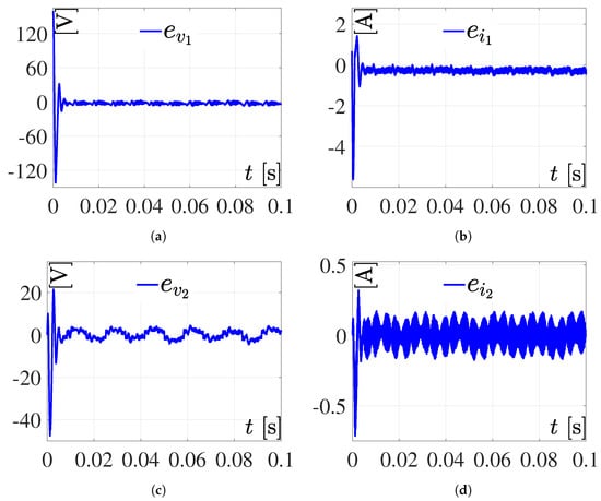
Figure 8.
Tracking errors related to simulation 3. (a) ; (b) ; (c) ; (d) .
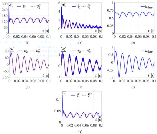
Figure 9.
Simulation 4. Response to the system for (27) and (28). (a,b,d,e,g) are the results of the simulation correspond to variables respectively; whereas the results related to the reference variables are . Meanwhile, (c,f) are the inputs of the DC/DC Boost converter and the full-bridge Buck inverter, respectively.
Simulation 1. In this simulation, the parameters selected are and in , and and in , for and , given by
The associated results for this simulation are shown in Figure 4. The tracking errors are defined as , , , and .
As can be seen in the simulation results presented in Figure 4 and Figure 5, with the system in open loop—i.e., not having a control algorithm that governs it—the DC/DC Boost converter–full-bridge Buck inverter and the system behave correctly; it can be observed that the system reproduces the programmed trajectory with an error. Further, it can be observed that the current consumption is not excessive and the inputs and are not saturated.
Simulation 2. Now, the energy reference and voltage are determined by (19) and (20) with the parameters , , and , , , selected as
The results for this simulation are shown in Figure 6.
The simulation results shown in Figure 6, performed using Bézier trajectories of order 25, show good performance even if the system is in open loop, and it is observed that the inputs and are not saturated.
Simulation 3. For this simulation, (19) is considered, where the initial and final energy parameters are directly proposed, i.e., and , given by
Meanwhile, is defined as
where A is the amplitude and P is the period, with values of and , respectively. The results for this simulation are shown in Figure 7.
The simulation results presented in Figure 7 and Figure 8 were performed using the Bézier trajectory for the energy described in (19), while the sinusoidal function described in (26) was used for the voltage. As can be seen, there is an over-impulse at the beginning of Figure 7a,b; this is due to the fact that the system is not controlled by any control technique, i.e., the system is in open loop. However, the DC/DC Boost converter–full-bridge Buck inverter system presents good performance since it manages to reproduce the reference trajectories adequately. Good performance is also achieved in the inputs and since they are not saturated.
Simulation 4. For this simulation, is the time-varying trajectory defined by
Now, is defined as a decreasing sinusoidal trajectory given by
where in (27) and (28), the values of A and P are as previously defined in (26). The results are shown in Figure 9.
After carrying out the simulation using a positive sinusoidal function for the energy and a decreasing sinusoidal signal for the voltage, the results presented in Figure 9 are obtained. As can be seen, the system is able to reproduce the reference trajectory, obtaining good results even when the system is in open loop.
3.3. Discussion for the Results Simulations
Simulations 1 and 2 (Figure 4 and Figure 6): In these simulations, reference trajectories with constant parts of Bézier type were considered, for and , in order to study the dynamic evolution of the system before work cycles ( and ), which are constant and variable in terms of time. From the simulations, it can be seen that . is found to be close to and they are dynamically very similar to each other. However, and differ in magnitude but not in shape, with respect to and . This is mainly due to the fact that parasitic resistances and energy losses were not considered within the model.
Simulations 3 and 4 (Figure 7 and Figure 9): For these simulations, appropriate trajectories of and are considered with the purpose of generating and variants in time. In these simulations, it is possible to observe that . With respect to the voltage of DC/DC Boost converter, is approaching , being dynamically very similar. Meanwhile, and differ in magnitude and not in shape, from their reference trajectories. This was explained in the previous paragraph.
4. Conclusions
In this work, the mathematical model of the DC/DC Boost converter–full-bridge Buck inverter system was analyzed through the property of differential flatness, by means of the flat outputs exhibited by the system. Energy trajectories for the DC/DC Boost converter as well as trajectories for the voltage of the full-bridge Buck inverter were proposed to observe the dynamic evolution of the system states. The simulations considered useful time-varying duty cycles for and and not just constants. The simulation results, in general, show good performance; this is due to the fact that in all the presented results the system reproduces the proposed trajectories adequately. Even considering that the system is in open loop, it is observed that the over-impulses of the states are stabilized and the inputs and are not saturated. Therefore, it is concluded that the analysis and validation of the system is satisfactory. As future work, it is necessary to apply control techniques that solve the tasks of regulation or trajectory tracking for and .
Author Contributions
Conceptualization, V.H.G.-R.; methodology, V.H.G.-R., J.H.P.-C. and R.C.A.-L.; simulations V.H.G.-R. and R.C.A.-L.; writing—original draft preparation, V.H.G.-R., J.H.P.-C. and S.T.-M.; writing—review and editing, V.H.G.-R., J.H.P.-C., R.C.A.-L. and S.T.-M.; supervision, V.H.G.-R., R.C.A.-L. and S.T.-M. All authors have read and agreed to the published version of the manuscript.
Funding
This research received no external funding.
Data Availability Statement
Not applicable.
Acknowledgments
The authors also thank the support of PRODEP-México program. V.H.G.-R. would like to thank SNI-CONACYT, J.H.P.-C. recognizes the support of EDI-IPN and SNI-CONACYT.
Conflicts of Interest
The authors declare no conflict of interest.
References
- Ryan, M.J.; Brumsickle, W.E.; Lorenz, R.D. Control topology options for single-phase UPS inverters. IEEE Trans. Ind. Applicat. 1997, 33, 493–501. [Google Scholar] [CrossRef]
- Zhou, Z.J.; Zhang, X.; Xu, P.; Shen, W.X. Single-phase uninterruptible power supply based on Z-source. IEEE Trans. Ind. Electron. 2008, 55, 2997–3004. [Google Scholar] [CrossRef]
- Minh-Huynh, D.; Ito, Y.; Aso, S.; Kato, K.; Teraoka, K. New concept of the DC-DC converter circuit applied for the small capacity uninterruptible power supply. In Proceedings of the 2018 International Power Electronics Conference, IPEC-Niigata 2018, Niigata, Japan, 20–24 May 2018; pp. 3086–3091. [Google Scholar]
- Chen, S.; Lipo, T.A. A novel soft-switched PWM inverter for AC motor drives. IEEE Trans. Power Electron. 1996, 11, 653–659. [Google Scholar] [CrossRef]
- Matsui, K.; Kawata, Y.; Ueda, F. Application of parallel connected NPC–PWM inverters with multilevel modulation for AC motor drive. IEEE Trans. Power Electron. 2000, 15, 901–907. [Google Scholar] [CrossRef]
- El-Bourhichi, S.; Oukassi, A.; El-Bahir, L.; El-Adnani, M. Active disturbance rejection control for a five-level cascaded H-bridge inverter fed induction motor sensorless field-oriented. Math. Probl. Eng. 2021, 2021, 9925072. [Google Scholar] [CrossRef]
- Tian, Z.; Lyu, Z.; Yuan, J.; Wang, C. UDE-based sliding mode control of DC–DC power converters with uncertainties. Control Eng. Pract. 2019, 83, 116–128. [Google Scholar] [CrossRef]
- Sivakumar, S.; Sathik, M.J.; Manoj, P.S.; Sundararajan, G. An assessment on performance of DC–DC converters for renewable energy applications. Renew. Sustain. Energy Rev. 2016, 58, 1475–1485. [Google Scholar] [CrossRef]
- Kwon, J.-M.; Nam, K.-H.; Kwon, B.-H. Photovoltaic power conditioning system with line connection. IEEE Trans. Ind. Electron. 2006, 53, 1048–1054. [Google Scholar] [CrossRef]
- Gokhale, K.P.; Kawamura, A.; Hoft, R.G. Dead beat microprocessor control of PWM inverter for sinusoidal output waveform synthesis. IEEE Trans. Ind. Applicat. 1987, IA-23, 901–910. [Google Scholar] [CrossRef]
- Pinheiro, H.; Martins, A.S.; Pinheiro, J.R. A sliding mode controller in single phase voltage source inverters. In Proceedings of the 20th Annual Conference of IEEE Industrial Electronics, IECON’94, Bologna, Italy, 5–6 September 1994; pp. 394–398. [Google Scholar]
- Tzou, Y.-Y. DSP-based fully digital control of a PWM DC-AC converter for AC voltage regulation. In Proceedings of the Power Electronics Specialist Conference, PESC ’95, Atlanta, GA, USA, 18–22 June 1995; pp. 138–144. [Google Scholar]
- Biel, D.; Fossas, E.; Guinjoan, F.; Alarcón, E.; Poveda, A. Application of sliding-mode control to the design of a Buck-based sinusoidal generator. IEEE Trans. Ind. Electron. 2001, 48, 563–571. [Google Scholar] [CrossRef]
- Ramos, R.R.; Biel, D.; Fossas, E.; Guinjoan, F. A fixed-frequency quasi-sliding control algorithm: Application to power inverters design by means of FPGA implementation. IEEE Trans. Power Electron. 2003, 18, 344–355. [Google Scholar] [CrossRef]
- Armstrong, M.; Atkinson, D.J.; Johnson, C.M.; Abeyasekera, T.D. Auto-calibrating DC link current sensing technique for transformerless, grid connected, H-bridge inverter systems. IEEE Trans. Power Electron. 2006, 21, 1385–1393. [Google Scholar] [CrossRef]
- Aroudi, A.E.; Rodríguez, E.; Orabi, M.; Alarcón, E. Modeling of switching frequency instabilities in buck-based DC–AC H-bridge inverters. Int. J. Circ. Theor. Appl. 2011, 39, 175–193. [Google Scholar] [CrossRef]
- Abrishamifar, A.; Ahmad, A.A.; Mohamadian, M. Fixed switching frequency sliding mode control for single-phase unipolar inverters. IEEE Trans. Power Electron. 2012, 27, 2507–2514. [Google Scholar] [CrossRef]
- Repecho, V.; Biel, D.; Olm, J.M.; Fossas, E. Sliding mode control of a voltage source inverter with switching frequency regulation. In Proceedings of the 2016 14th International Workshop on Variable Structure Systems, VSS, Nanjing, China, 1–4 June 2016; pp. 296–301. [Google Scholar]
- Awais, M.; Yasin, A.R.; Riaz, M.; Saqib, B.; Zia, S.; Yasin, A. Robust sliding mode control of a unipolar power inverter. Energies 2021, 14, 5405. [Google Scholar] [CrossRef]
- Caceres, R.O.; Barbi, I. A Boost DC–AC converter: Analysis, design, and experimentation. IEEE Trans. Power Electron. 1999, 14, 134–141. [Google Scholar] [CrossRef]
- Olm, J.M.; Biel, D.; Spinetti-Rivera, M.; Fossas, E. Harmonic balance-based control of a Boost DC/AC converter. Int. J. Circ. Theor. Appl. 2012, 40, 777–792. [Google Scholar] [CrossRef]
- Abramovitz, A.; Zhao, B.; Smedley, K. High-Gain single-stage Boosting inverter for photovoltaic applications. IEEE Trans. Power Electron. 2016, 31, 3550–3558. [Google Scholar] [CrossRef]
- Wang, C.-M. A novel single-stage full-bridge Buck-Boost inverter. IEEE Trans. Power Electron. 2004, 19, 150–159. [Google Scholar] [CrossRef]
- Abdel-Rahim, O.; Orabi, M.; Ahmed, M.E. Buck-Boost interleaved inverter for grid connected photovoltaic system. In Proceedings of the 2010 IEEE International Conference on Power and Energy, Kuala Lumpur, Malasya, 29 November–1 December 2010; pp. 63–68. [Google Scholar]
- Tripathi, P.R.; Thakura, P.; Keshri, R.K.; Ghosh, S.; Guerrero, J.M. Twenty-five years of single-stage Buck–Boost inverters. IEEE Ind. Electron. Mag. 2022, 16, 4–10. [Google Scholar] [CrossRef]
- Sira-Ramírez, H.; Agrawal, S.K. Differentially Flat Systems; Marcel Dekker: New York, NY, USA, 2004; ISBN 9780824754709. [Google Scholar]
- Gil-Antonio, L.; Saldivar, B.; Portillo-Rodríguez, O.; Ávila-Vilchis, J.C.; Martínez-Rodríguez, P.R.; Martínez-Méndez, R. Flatness-based control for the maximum power point tracking in a photovoltaic system. Energies 2019, 12, 1843. [Google Scholar] [CrossRef]
- Gil-Antonio, L.; Saldivar, B.; Portillo-Rodríguez, O.; Vázquez-Guzmán, G.; Montes de Oca-Armeaga, S. Trajectory tracking control for a Boost converter based on the differential flatness property. IEEE Access 2019, 7, 63437–63446. [Google Scholar] [CrossRef]
- Silva-Ortigoza, R.; Hernández-Guzmán, V.M.; Antonio-Cruz, M.; Muñoz-Carrillo, D. DC/DC Buck power converter as a smooth starter for a DC motor based on a hierarchical control. IEEE Trans. Power Electron. 2015, 30, 1076–1084. [Google Scholar] [CrossRef]
- Rigatos, G.; Siano, P.; Ademi, S.; Wira, P. Flatness-based control of DC–DC converters implemented in successive loops. Electric Power Compon. Syst. 2018, 46, 673–687. [Google Scholar] [CrossRef]
- Arshad, M.H.; Abido, M.A. Hierarchical control of DC motor coupled with Cuk converter combining differential flatness and sliding mode control. Arab. J. Sci. Eng. 2021, 46, 9413–9422. [Google Scholar] [CrossRef]
- Silva-Ortigoza, R.; Alba-Juárez, J.N.; García-Sánchez, J.R.; Antonio-Cruz, M.; Hernández-Guzmán, V.M.; Taud, H. Modeling and experimental validation of a bidirectional DC/DC Buck power electronic converter-DC motor system. IEEE Lat. Am. Trans. 2017, 15, 1043–1051. [Google Scholar] [CrossRef]
- García-Rodríguez, V.H.; Silva-Ortigoza, R.; Hernández-Márquez, E.; García-Sánchez, J.R.; Taud, H. DC/DC Boost converter-inverter as driver for a DC motor: Modeling and experimental verification. Energies 2018, 11, 2044. [Google Scholar] [CrossRef]
- Hernández-Márquez, E.; Silva-Ortigoza, R.; García-Sánchez, J.R.; García-Rodríguez, V.H.; Alba-Juárez, J.N. “A new DC/DC Buck-Boost converter–DC motor” system: Modeling and experimental validation. IEEE Lat. Am. Trans. 2017, 15, 2043–2049. [Google Scholar] [CrossRef]
- Hernández-Márquez, E.; Avila-Rea, C.A.; García-Sánchez, J.R.; Silva-Ortigoza, R.; Marciano-Melchor, M.; Marcelino-Aranda, M.; Roldán-Caballero, A.; Márquez-Sánchez, C. New “full-bridge Buck inverter–DC motor” system: Steady-state and dynamic analysis and experimental validation. Electronics 2019, 8, 1216. [Google Scholar] [CrossRef]
- Hernández-Márquez, E.; Avila-Rea, C.A.; García-Sánchez, J.R.; Silva-Ortigoza, R.; Silva-Ortigoza, G.; Taud, H.; Marcelino-Aranda, M. Robust tracking controller for a DC/DC Buck-Boost converter–inverter–DC motor system. Energies 2018, 11, 2500. [Google Scholar] [CrossRef]
- García-Sánchez, J.R.; Hernández-Márquez, E.; Ramírez-Morales, J.; Marciano-Melchor, M.; Marcelino-Aranda, M.; Taud, H.; Silva-Ortigoza, R. A robust differential flatness-based tracking control for the “MIMO DC/DC Boost converter-inverter-DC motor” system: Experimental results. IEEE Access 2019, 7, 84497–84505. [Google Scholar] [CrossRef]
- Silva-Ortigoza, R.; Hernández-Márquez, E.; Roldán-Caballero, A.; Tavera-Mosqueda, S.; Marciano-Melchor, M.; García-Sánchez, J.R.; Hernández-Guzmán, V.M.; Silva-Ortigoza, G. Sensorless tracking control for a “full-bridge Buck inverter–DC motor” system: Passivity and flatness-based design. IEEE Access 2021, 9, 132191–132204. [Google Scholar] [CrossRef]
- Silva-Ortigoza, R.; Marciano-Melchor, M.; García-Chávez, R.E.; Roldán-Caballero, A.; Hernández-Guzmán, V.M.; Hernández-Márquez, E.; García-Sánchez, J.R.; García-Cortés, R.; Silva-Ortigoza, G. Robust flatness-based tracking control for a “full-bridge Buck inverter–DC motor” system. Mathematics 2022, 10, 4110. [Google Scholar] [CrossRef]
- Biel, D.; Guinjoan, F.; Fossas, E.; Chavarria, J. Sliding-mode control design of a Boost–Buck switching converter for AC signal generation. IEEE Trans. Circuits Syst. 2004, 51, 1539–1551. [Google Scholar] [CrossRef]
- Sira-Ramírez, H.; Silva-Ortigoza, R. Control Design Techniques in Power Electronics Devices; Springer: London, UK, 2006; ISBN 978-1-84628-458-8. [Google Scholar]
- Silva-Ortigoza, R.; Márquez-Sánchez, C.; Carrizosa-Corral, F.; Antonio-Cruz, M.; Alba-Martínez, J.M.; Saldaña-González, G. Hierarchical velocity control based on differential flatness for a DC/DC Buck converter-DC motor system. Math. Probl. Eng. 2014, 2014, 912815. [Google Scholar] [CrossRef]
- Biagiotti, L.; Melchiorri, C. Trajectory Planning for Automatic Machines and Robots; Springer: London, UK, 2008; ISBN 978-3-540-85628-3. [Google Scholar]
Disclaimer/Publisher’s Note: The statements, opinions and data contained in all publications are solely those of the individual author(s) and contributor(s) and not of MDPI and/or the editor(s). MDPI and/or the editor(s) disclaim responsibility for any injury to people or property resulting from any ideas, methods, instructions or products referred to in the content. |
© 2023 by the authors. Licensee MDPI, Basel, Switzerland. This article is an open access article distributed under the terms and conditions of the Creative Commons Attribution (CC BY) license (https://creativecommons.org/licenses/by/4.0/).