Article

Drilling in Gas Hydrates: Managing Gas Appearance Risks

1
Saint Petersburg Mining University, 199106 Saint Petersburg, Russia
2
PJSC Gazprom, 197229 Saint Petersburg, Russia
*
Author to whom correspondence should be addressed.
Energies 2023, 16(5), 2387; https://doi.org/10.3390/en16052387
Submission received: 3 January 2023 / Revised: 24 February 2023 / Accepted: 28 February 2023 / Published: 2 March 2023
(This article belongs to the Special Issue Modern Trends in Oil and Gas Industry)

Abstract

:
This article provides a detailed analysis of issues related to the complications while drilling in hydrate-bearing rocks of permafrost areas. The goal of the paper is to develop recommendations for preventing gas occurrence while drilling gas hydrate deposits and to eliminate gas leakiness of the intercasing space of the well. The results of modeling the effect of drilling mud injection on the temperature field of the well are presented. It is revealed that the most significant role is played by the injection rate of drilling mud and its temperature. The recommended flow rate of the process fluid should be within 0.30–0.45 m3/s, and its temperature should not exceed 20 °C. Controlling the parameters of drilling mud and its flow rate allows for avoiding intensive gas occurrence while drilling in gas hydrates. The presence of gas hydrates may be the cause of gas leakiness of the intercasing space in the permafrost area. One of the ways to eliminate leakiness is colmatation (clogging). A method of preventing leaks in the intercasing space of the gas well is the use of colmatating solution. An aqueous solution of sodium silicate with the addition of 2% polymer is used as a colmatating composition.

1. Introduction

Almost all of the largest Russian natural gas fields are located in the Yamalo-Nenets Autonomous Okrug, Yakutia, the waters of the Kara Sea, and in other territories that are united by the presence of permafrost areas [1]. A large new gas field, “Pobeda”, was discovered in the Kara Sea relatively recently (2014). A preliminary assessment of the field showed that it contains at least 338 billion cubic meters of gas [2].
A significant part of the methane deposits in these fields are concentrated in the traditional gas form, and the technologies for drilling and operating such gas wells are widely known and understood. In 1946, Soviet researcher I.N. Strizhov, for the first time, suggested that certain thermobaric conditions in the permafrost formations contribute to the generation of so-called gas hydrates with a particularly high probability [3]. Much later, in 1968, a core containing inclusions of gas hydrates was obtained at the Byrd station in the Antarctica while drilling exploration wells [4].
Many gas hydrate deposits have been discovered in the USA [5,6,7,8], in Canada [9,10] in permafrost areas, India, and others [11].
Natural gas hydrates are crystalline compounds in the form of polyhedra formed by water molecules interconnected by hydrogen bonds, inside which (polyhedra) a methane molecule is encapsulated. The reserves of methane in hydrate form are huge and hundreds of times higher than the reserves of natural gas in traditional phases. For the formation of hydrate clusters, few conditions must be complied with; first, favorable thermobaric conditions and a continuous inflow of free gas [12,13]. For methane hydrates, the equilibrium curve is shown in Figure 1a (based on data from [14], and the methane hydrate-propane mixture is shown in Figure 1b) [15]. It should be noted that the reservoir conditions of most of the mentioned fields are significantly above the equilibrium curve, which indicates a high probability of accumulation of natural gas hydrates.
The stability of gas hydrates is influenced by some other factors: the granulometric and chemical composition of the host rock, its porosity, density, as well as the mineralization of reservoir waters [14,15,16,17]. For example, the higher the degree of mineralization, the less temperature needed for the formation of natural gas hydrate.
As noted by a number of authors [18,19,20,21], in permafrost rocks, there are metastable gas hydrates formed earlier and subjected to self-preservation at negative temperatures, which are commonly called relict. It should be emphasized that gas hydrates cannot form under metastable conditions, but they can remain within them for a long time if the frozen state of the thickness is preserved.
The phenomenon of self-preservation is explained by the fact that while the external pressure decreases, the dissociation of the gas hydrate begins with the release of water, which crystallizes at temperatures below 273 K and creates an insulating layer of ice on the surface of the hydrate, which significantly slows down the further decomposition of the hydrate [22,23,24]. Temperature has a predominant effect on the rate of dissociation of gas hydrates.
The study of metastable hydrates was not given enough attention until their existence was proven. It was found that metastable gas hydrates are at lower depths compared to the modern stability zone of classical methane hydrates. In connection with the above, to date, gas occurrences during drilling of the upper intervals have not been associated with the presence of gas hydrates. While the most intense gas manifestations have been observed above the intervals of stable gas hydrates. However, the discovery of relic formations has given a new impetus to the study of hydrate deposits and the problems associated with their development.
There is also research being conducted into gas hydrates exploitation. As part of the research project, production tests were carried out on three gas wells, Mallik 3L-38, 4L-38, and 5L-38 in 2001 by Japan and Canada (Petroleum Exploration Company Limited, Japan National Oil Corporation, Geological Survey of Canada) [25,26,27]. In 1995, the U.S. Geological Survey conducted the first comprehensive assessment of gas hydrate resources in the United States (Ocean Drilling Program Leg 164). In 1997, the Ministry of Oil and Gas of India established the National Gas Hydrate Program (NGHP). In 1998, work began on the Canadian Mallik project, and in 1999 on the Nankai Trough project in Japan. Since 2000, Japan has established a targeted program for the study of gas hydrates, forming the MH21 research consortium to develop technologies for the industrial production of gas hydrates. Currently, two projects have major prospects for industrial production—Nankai Trough (MH21) in Japan and North Slope in Alaska (USA) [28,29]
In recent years, many drilling operations have been carried out in areas of hydrate deposits [30,31,32].
Scientists have conducted research to study the kinetics and thermodynamics of the formation and dissociation of gas hydrates [33,34]. The paper [10] presented the results of modeling the conditions of the formation of relic gas hydrates using the example of deposits of the Beaufort Mackenzie field. The prevalent influence of temperature and lithological characteristics on the conservation effect of natural gas hydrates was shown. The article [17] presented the results of laboratory experiments on the making of methane gas hydrates and the rate of hydrate formation on different thermobaric conditions
Therefore, the discovery of huge natural gas reserves in a non-traditional form presents many opportunities for the development of new deposits, increasing the competitiveness of the country in terms of environmentally friendly energy resources [35,36]. Many countries of the world have invested in the development of gas hydrate deposits as new energy sources.
On the other hand, when drilling and developing wells for classical gas, gas condensate, and oil fields, passage through the zone of gas hydrate deposits inevitably causes a change in the thermodynamic state of the formation-well system. At the same time, even small changes in the thermobaric conditions in the formation inevitably cause the decomposition of hydrates with the release of free methane and water. Two opposite phenomena—the dissociation of existing hydrate formations and the formation of technogenic hydrates—provoke dangerous complications during drilling and pose a serious problem. A description of the problem of the formation of technogenic hydrates and ways to solve it are given in [37,38,39,40,41].
There are no universal ways to avoid complications while drilling wells in the gas hydrate deposit. Some solutions are described in [32]. However, these recommendations do not completely avoid intense gas occurrences while drilling gas hydrates.
This paper is devoted to solving the problem associated with the decomposition of gas hydrates while drilling in the permafrost area. The problem, which significantly complicates the process of drilling in gas hydrate deposits, is due to the fact that, while drilling hydrate-saturated formations, the use of drilling fluids with a positive (Celsius scale) temperature inevitably leads to complications associated with the reaction of permafrost rocks to changes in the temperature regime around the well.
Intensive gas appearance is most often observed as a complication while drilling in hydrate-bearing rocks. It is associated with the thermal dissociation of gas hydrates. This process leads to a sharp increase in pressure in the around-well space and sometimes the formation of a gas bubble, the volume of which could be hundreds of times greater than the volume of decomposed hydrate. Long-term gas appearances are possible in the presence of a volume of free methane that is not associated with water due to the insufficient amount of free water for equilibrium [41].
Sometimes the problem can be solved by using a drilling mud of a higher density, but more often complications cannot be avoided. The gas appearances lead to the aeration of drilling mud, the release of tools and bore mud, griffins, and fires. If the gushing of gas and griffins continues for a long enough time, this can lead to the melting of ice in permafrost rocks around the borehole, and subsequently, to the collapse of the drilling column.
The absorption of energy accompanying the process of dissociation of natural hydrates cause a local decrease in temperature, which contribute to hydrate formation. Thus, during drilling and the development and testing of the well, problems associated with the formation of a gas bubble and blockage of the borehole by technogenic hydrates simultaneously arise, which, together, lead to the destruction of the well. There are cases where, after an intensive release of gas, its inflow is sharply reduced. This is due to a significant decrease in temperature in the formation, which occurs due to heat absorption and causes freezing of the remaining gas hydrates [39,42].
Especially serious complications associated with the formation of technogenic hydrates can occur when drilling wells on offshore shelves, since there is a possibility of mixing the gas entering the well with water, which dramatically increases the likelihood of hydrate plug formation at low temperatures.
As noted above, an increase in temperature causes the decomposition of hydrates with the release of a significant amount of methane, which increases the pressure in the system, while the simultaneous melting of ice creates, on the contrary, a pressure deficit. The resulting pressure difference contributes to the destruction of sandy and loose deposits, which are accompanied by intensive pore formation and the removal of rock particles by the flow of drilling fluids, which ultimately threatens the possible destruction of the well and loss of control over it.
A number of authors have also noted that uncontrolled methane emissions pose a threat to the environment and can affect global warming due to the “greenhouse” effect no less than carbon dioxide, which is considered to be the main culprit of climate change on the planet. According to the theory of some scientists, an increase in the average temperature of the climate system on Earth and the release of methane from gas hydrates have a symbiotic effect: the release increases as a result of warming, and vice versa. However, this version has not been confirmed by most scientists and is still considered controversial [39,42,43,44,45].
Another problem of drilling wells in the permafrost zone is the formation of ice in the process of plugging a well, which leads to the destruction of cement and the rock collapses into the wellbore [46]. The destruction of the cement sheath leads to cracks in the intercasing space and to the appearance of intercasing leakiness. The problem with leakiness in the intercasing space with gas flows from low-temperature intervals is also relevant for oil and gas wells located in the permafrost area
Scientists of Saint Petersburg Mining University have also worked on the development of cements with improved characteristics [47,48,49].
The Department of Well Drilling at Saint Petersburg Mining University has conducted research aimed at improving the parameters of muds used in drilling [50,51,52,53] and well construction [47,54,55,56].
The cementing process is an important step in the safe construction and operation of wells in permafrost conditions.
For gas wells located in the permafrost zone, concrete must possess high mechanical strength characteristics, resistance to corrosion from aggressive fluids, fit tightly within the casing strings and well walls, have structural resistivity to temperature fluctuations, and low thermal conductivity, amongst other considerations [56].
The appearance of leaks in the intercasing space of a gas well can be facilitated by both poor-quality cementing at the construction stage, as well as physical and chemical processes and geological features. The presence of gas hydrates in the target intervals can also be associated with gas leakage in the intercasing space of the well [52].
Most production wells of the Gubkinskoe gas field have leakiness in the intercasing space. The positive temperature of the gas (up to 20 °C) is one of the reasons for the warming of the near-well space. Sharp temperature changes in the near-well space lead to cracks in the cement sheath of the well.
At the exploration well R-49 of the Gubkinskoe gas field, leakage into the intercasing space of the technical case and the conductor was recorded in the intervals of the permafrost area using a wellhead pressure and temperature gauge. Observations showed that, from November 2020 to July 2021, the pressures in the intercasing space continuously increased, which is clearly illustrated in Figure 2.
The most intense warming of the near-well space occurs while drilling wells. A modeling of drilling mud injection was carried to determine the effect of the fluid on the warming of the near-well space in permafrost conditions. The results can also be used to describe the warming of the near-well space during gas production.

2. Modeling of the Effect of Drilling Mud Injection on the Temperature Field of the Wellbore Space

The model was developed using the COMSOL Multiphysics element analysis software package. The simulation was carried out on the basis of the well-known laws of heat transfer, hydrodynamics, and rheology. It allows simulates the flow of drilling mud of a given temperature into the well hole and assess the effect of the flow rate on the temperature of the rock around the well.
The following assumptions were made in modeling the temperature field:
  • Gas hydrate deposits have low permeability. As a result, there is no convection because the penetration of the liquid phase into the rock is quite small. It means that the predominant method of heat transfer is thermal conductivity.
  • The rock is homogeneous and has isotropic properties.
  • To describe the geometry of the model, several coaxial bodies of rotation are used, simulating a pipe, a liquid inside and outside, and a borehole space.
  • The melting of pore ice occurs at 0 °C, and the thermophysical properties of rocks do not depend on temperature
  • The initial temperature of the liquid, pipe, and rock is constant in a plane perpendicular to the axis of the well.
The well-known Fourier equation of thermal conductivity is taken as the mathematical basis of modeling:
d q = λ d t d n d F d τ ,
d q —quantity of heat; λ —the coefficient of thermal conductivity, W/mK; d t —temperature gradient; d F —surface area gradient; d τ —time gradient.
The calculations take into account thermal conductivity both in the liquid and in the solid phase, while it is assumed that, in the model of a porous medium, the porosity is zero for a solid, and the porosity is equal to one for a liquid body.
Fourier’s law:
q = k m e d T
where T—temperature, K,
k m e d equals to:
k m e d = θ p k p + ( 1 θ p ) k + k d i s p
and represents the average thermal conductivity between the thermal conductivities of the liquid k (W/m∙K) and solid phases k_p (W/m∙K) according to mass fractions considering the filtering liquid through a porous medium via the so-called thermal dispersion coefficient; the calculation method of this coefficient is presented in detail in [54].
Formula (3) includes θ p —the proportion of the solid phase in the volume, respectively, 1 − θ p —is the proportion of the liquid phase.
Considering the volumetric heat capacity ( ρ C p ) m e d , here is the general equation for the entire medium:
( ρ C p ) m e d T t + ρ C p u T + q = Q + Q v d
In Equation (4), ρ   and   ρ p —density of the liquid and solid phase, respectively, kg/m3; and C p and C p p are the heat capacity of the liquid and solid phase at constant pressure,   J / kg ; u—is the velocity of the liquid in the pores of the solid phase, m/s; q—heat flow, W/m2, Q   и   Q v d —heat source or absorber and heat released during viscous friction W/m3, respectively. Q v d is very small compared to other heat fluxes and can be considered to be zero.
This equation does not take into account the volume expansion coefficient α due to its small value. The model for heat transfer in the liquid phase is represented by Formula (7) if θ p equals 0.
The formula for calculating heat transfer in porous rock is the following:
{ k m e d = θ p k p + ( 1 θ p ) k + k d i s p q = k m e d T ( ρ C p ) m e d = θ p ρ p C p p + ( 1 θ p ) ρ C p ( ρ C p ) m e d T t + ρ C p u T + q = Q + Q v d
Model of the solid pipe material:
{ q = k T ρ C p T t + ρ C p u T + q = Q + Q t e d
{ q = k T ρ C p T t + ρ C p u T + q = Q + Q v d
After the calculation, the temperature distribution at different times is analyzed.
An example of initial data for initializing a computational experiment is given in Table 1:
Figure 3 shows the temperature distribution of the host rock before and after the fluid injection.
Figure 4 shows the change in the formation temperature around the well after 1 min and 4 h from the start of the fluid injection process.
Based on simulation modeling results, in case of other things being equal, the parameters such as the drilling fluid and its injection rate and temperature play the most significant role. At the same time, these parameters do not practically affect the heat transfer radius in the rock mass of more than 0.4 m. It can be explained by the incomparable volumes of the drill pipe and the space around the wall.
The recommended process fluid flow rate should be in the range of 0.30–0.45 m3/s, and its temperature should not exceed 20 °C. At the same time, it is necessary to keep in mind the increased probability of drilling fluid solidification in permafrost conditions due to a local decrease in temperature as a result of the endothermic dissociation of gas hydrates.
The proposed technique will significantly reduce the risk of complications associated with gas occurrences while drilling in hydrate-bearing deposits. Based on the simulation results it can be concluded that it is impossible to avoid intensive warming of the near-well space. This process can lead to the dissociation of gas hydrates.
Warming of the near-well space in the production well can also causes dissociation of gas hydrates and gas leakage in the intercasing space. The leakproofness of the intercasing space avoids gas leakages.
A method of preventing leaks in the intercasing space of gas well is to use colmatating solution [57].

3. Materials and Methods

The colmatation method is chosen by pressurizing the colmatating solution into the gate valve of the intercasing cement space.
The sealant solution is prepared on site prior to being pumped into the well according to the developed technique.
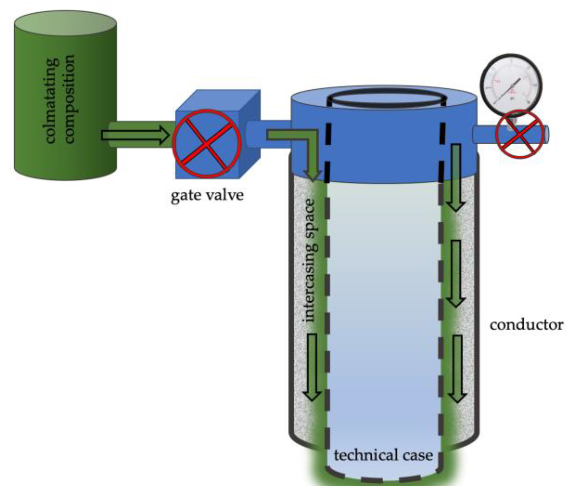
  • Before introducing the sealant through the inlet conduit of the gate valve of the intercasing space, the pressure is lowered. Pressure control is carried out using a wellhead pressure and temperature gauge.
  • Once atmospheric pressure has been achieved, the colmatating composition is pumped through the gate valve using.
  • Following the injection, the colmatating solution is allowed to set for 24 h (Figure 5).
Leakproofness is checked after colmatation of the intercasing space by crimping. According to paragraph 424 of the document “Safety rules in the oil and gas industry”, the intercasing space is considered sealed if the pressure of crimping has decreased by no more than 0.5 MPa within 30 min.
4.
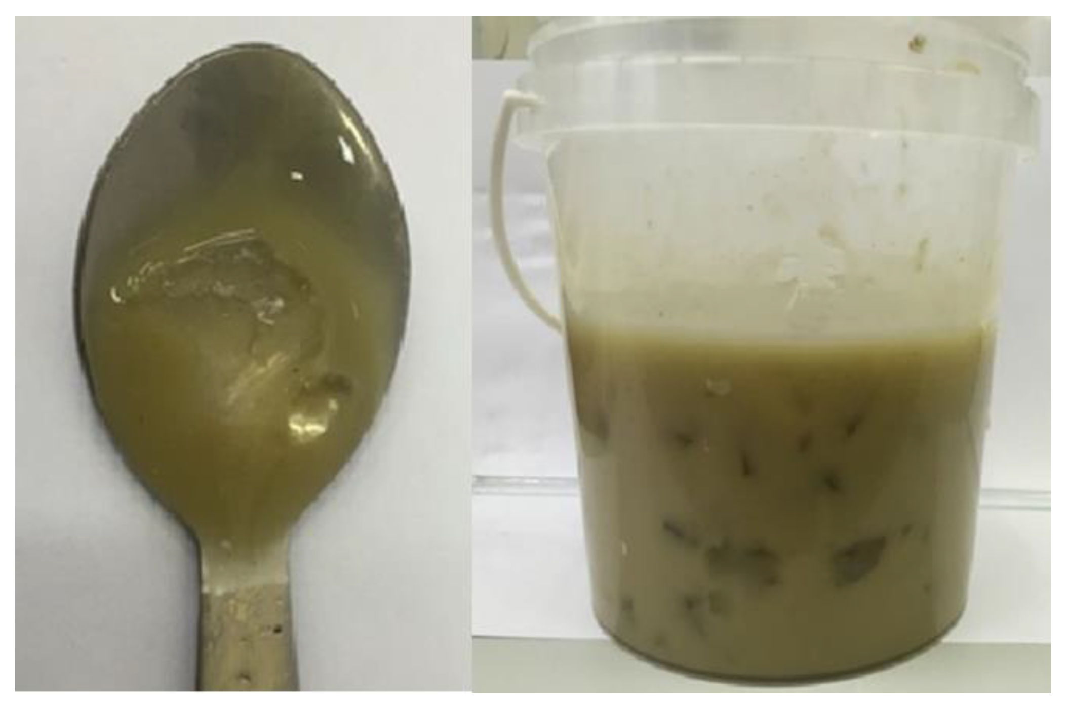
Colmatation (clogging) involves the introduction of fine particles of solution or other materials into pores, channels, and cracks in the intercasing space, which helps to reduce or completely stop the gas or fluid flows by reducing the filtration properties of the cement. The success of the operation to seal the intercasing space depends on the development of the colmatating solution.
The most important requirements for the colmatating solution are the particle size of the colmatant, the viscosity of the solution, and its curing ability. Since in most cases colmatating solutions are non-Newtonian liquids, the rheological properties of the solution, such as viscosity and yield point, are important [58].
Elimination of leakiness in the intercasing space was carried out using the developed colmatating composition.
Reagents for research were purchased from the Joint-stock company Lenreactive and Joint-stock company Ruskhimset.
The following materials were used as samples of polymer materials:
copolymer of polyacrylamide (Figure 6) and sulfonic acid (Polymer X20 or equivalent);
organosilicon polymer.
The work was carried out in accordance with the existing methods of experimental research. The structural and rheological characteristics of aqueous polymer solutions were measured using a Fann 35S viscometer. Plastic viscosity (PV), yield point (YP), and gel strength were measured according to specifications using a Fann 35S viscometer.

4. Results

As a result of rheological and structural research of organosilicon polymer, immeasurable values of viscosity and yield point were obtained, which indicated the inapplicability of this polymer. The research of the characteristics was carried out in a concentration range from 1 to 10%. Optimal rheological and structural characteristics of aqueous solution of polyacrylamide were obtained at a concentration of no more than 4%.
Characteristics of aqueous solution of polyacrylamide are shown in Table 2.
The next step in the research is studying the effect of the polyacrylamide on the structural and rheological characteristics directly on the aqueous solution of sodium silicate (State Standard 13078-81) [59]. Characteristics of aqueous solution of sodium silicate and polyacrylamide are shown in Table 3.
Measurable values of plastic viscosity and yield point were obtained for concentrations of polyacrylamide less than 2%.
An aqueous solution of sodium silicate with the addition of 2% polymer was used as a colmatating composition. Polyacrylamide is a water-swelling polymer and this polymer blocks the channels in the cement after swelling.

5. Discussion

The well R-49 is located in the permafrost area. Sodium silicate crystallizes at low temperatures provided additional colmatating ability of the developed composition. After colmatation of the intercasing space, the crimping pressure decreased by less than 0.5 MPa for 30 min, which indicates the leakproofness of the intercasing space.
The use of developed colmatating solution made it possible to eliminate the leaks in the intercasing space of a gas well, to ensure compliance with the requirements of the «Safety Rules of the oil and gas industry» and protect the environment. Monthly monitoring of the leakiness of the intercasing space is carried out at the well R-49 (Figure 7).
The intercasing pressures do not exceed 0.05 MPa, which indicates the tightness of the intercasing space and the positive result of the research.

6. Conclusions

The developed model makes it possible to simulate the flow-in of drilling mud into the well and to assess the effect of the flow rate and parameters of drilling mud on the change in the temperature field around the wellbore. The conducted studies have shown that changing the parameters of drilling mud and its flow rate allows for avoiding intensive gas occurrence while drilling in gas hydrates. While drilling in gas hydrate deposits of permafrost rocks, the flow-in of drilling mud and its temperature have a decisive effect on the intensity of warming of the near–well zone. At the same time, it does not practically affect the radius of heat transfer through the rock mass, which does not exceed 0.4 m. The recommended flow-in of the drilling should be in the range of 0.30–0.45 m3/s, and its temperature should not exceed 20 °C. These recommendations allow for the safest drilling in permafrost intervals with the risk of gas occurrences because of the dissociation of relict gas hydrate deposits. However, the drilling well with the recommended parameters does not completely avoid the dissociation of gas hydrates.
The thawing of permafrost gas hydrates during gas production is also a reason for gas migration in the intercasing space. The method of colmatation (clogging) using the developed polymer solution eliminates the gas leakiness of the intercasing space in production wells.

Author Contributions

Conceptualization, M.D. and R.G.; methodology, R.G.; software, R.G.; validation, R.G., formal analysis, N.R.; investigation, N.R.; resources, V.N.; data curation, V.N.; writing—original draft preparation, N.R.; writing—review and editing, N.R. All authors have read and agreed to the published version of the manuscript.

Funding

This research received no external funding.

Data Availability Statement

Not applicable.

Conflicts of Interest

The authors declare no conflict of interest.

References

  1. Elesin, M.A. On the Prospects of Creating a Permafrost Laboratory and the Main Directions of its Development. Sci. Bull. Arct. Sci. Pract. J. 2019, 7, 16–21. Available online: https://www.norvuz.ru/upload/iblock/ef0/ef0b76ca61be815bfcaf111e6f9b975f.pdf (accessed on 2 January 2023).
  2. Litvinenko, V.S.; Kozlov, A.V.; Stepanov, V.A. Hydrocarbon potential of the Ural–African transcontinental oil and gas belt. J. Pet. Explor. Prod. Technol. 2017, 7, 1–9. [Google Scholar] [CrossRef] [Green Version]
  3. Makogon, Y.F. Natural gas hydrates: Distribution, education models, resources. Russ. Chem. Mag. 2003, 47, 70–79. [Google Scholar]
  4. Birchwood, R.; Dai, J.; Shelander, D.; Boswell, R.; Collett, T.; Cook, A.; Dallimore, S.; Fujii, K.; Imasato, Y.; Fukuhara, M.; et al. Developments in Gas Hydrates. Oilfield Rev. 2010, 22, 18–33. [Google Scholar]
  5. Stern, L.; Lorenson, T.; Pinkston, J. Gas hydrate characterization and grainscale imaging of recovered cores from the Mount Elbert gas hydrate stratigraphic test well. Alsk. N. Slope. Mar. Pet. Geol. 2011, 28, 394–403. [Google Scholar] [CrossRef]
  6. Boswell, R.; Hunter, R.; Collett, T.; Digert, S.; Hancock, M.; Weeks, M. Investigation of Gas Hydrate Bearing Sandstone Reservoir at the “Mount Elbert” Stratigraphic Test Well, Milne Point, Alaska. In Proceedings of the International Conference on Gas Hydrates (ICGH 2008), Vancouver, AB, Canada, 6–10 July 2008. [Google Scholar]
  7. Boswell, R.; Schoderbek, D.; Collett, T.S.; Ohtsuki, S.; White, M.; Anderson, B.J. The Iġnik Sikumi field experiment, Alaska North Slope: Design, operations, and implicationsfor CO2-CH4 exchange in gas hydrate reservoirs. Energy Fuels 2017, 31, 140–153. [Google Scholar] [CrossRef]
  8. Hunter, R.; Collett, T.; Boswell, R.; Anderson, B.; Digert, S.; Pospisil, G.; Baker, R.; Weeks, L. Mount Elbert Gas Hydrate Stratigraphic TestWell, Alaska North Slope: Overview of scientific and technical program. J. Mar. Pet. Geol. 2011, 28, 295–310. [Google Scholar] [CrossRef]
  9. Majorowicz, J.A.; Hannigan, P.K. Natural Gas Hydrates in the Offshore Beaufort–Mackenzie Basin—Study of a Feasible Energy Source II. Nat. Resour. Res. 2000, 9, 201–214. [Google Scholar] [CrossRef]
  10. Majorowicz, J.; Osadetz, K.; Safanda, J. Models of Talik, Permafrost and Gas Hydrate Histories—Beaufort Mackenzie Basin, Canada. Energies 2015, 8, 6738–6764. [Google Scholar] [CrossRef] [Green Version]
  11. Gong, Y.; Xu, T.; Yuan, Y.; Xin, X.; Zhu, H. Optimal design of the field hydrate production test in the offshore India: Insights from the vertically heterogeneous hydrate reservoir model. J. Nat. Gas Sci. Eng. 2022, 103, 104645. [Google Scholar] [CrossRef]
  12. Yakushev, V.S. Formation of Accumulations of Natural Gas and Gas Hydrates in the Cryolithozone; Research Institute of Natural Gases and Gas Technologies: Razvilka, Russia, 2009; pp. 41–47. 47p. [Google Scholar]
  13. Safronov, A.F.; Shits, E.Y.; Grigoriev, M.N.; Semenov, M.E. The problem of formation of gas hydrate deposits on the shelf of the Arctic seas of Siberia. Geol. Geofiz. 2010, 51, 106–112. [Google Scholar]
  14. Argunova, K.K.; Bondarev, E.A.; Nikolaev, V.E.; Rozhin, I.I. Determination of the Hydrate Formation Interval in Wells Drilled in Permafrost Rocks [Electronic Resource]. Electron. Sci. J. Oil Gas Bus. 2008. Available online: http://www.ogbus.ru/authors/Argunova/Argunova_2.pdf (accessed on 2 January 2023).
  15. Faresov, A.V.; Ponomarev, A.I.; Kruglov, E.A.; Baryaev, A.P. Comparison of the Effectiveness of Kinetic-Type Hydrate Formation Inhibitors and the Experience of Their Industrial Application in PJSC “Surgneft” Vesti gazovoy nauki. Actual Probl. Gas Prod. 2016, 26. Available online: https://ozneftehim.ru/articles/vesti-gazovoi-nauki-02-2016/ (accessed on 2 January 2023).
  16. Istomin, V.A.; Izyumchenko, D.V.; Lapshin, V.I.; Kosachuk, G.P.; Burakova, S.V.; Bututkina, S.I. About the Possible Hydrate Saturation of Porous Media of Low-Temperature gas Deposits. In The Collection “Efficiency of Hydrocarbon Reserves Development”. Part 2 “Development and Operation of Deposits. Complex Studies of Oil and Gas Condensate Reservoir Systems”; Gazprom VNIIGAZ: Ukhta, Russia, 2010; pp. 32–45. [Google Scholar]
  17. Bazaluk, O.; Sai, K.; Lozynskyi, V.; Petlovanyi, M.; Saik, P. Research into Dissociation Zone of Gas Hydrate Deposit with a Heterogeneous Structure in the Black Sea. Energies 2021, 14, 1345. [Google Scholar] [CrossRef]
  18. Perlova, E.V.; Miklyaeva, E.S.; Leonov, S.A.; Tkacheva, E.V.; Ukhova, Y.A. Gas hydrates of the Yamal Peninsula and the adjacent shelf of the Kara Sea as a complicating factor in the development of the region. News Gas Sci. 2017, 3, 255–262. [Google Scholar]
  19. Melnikov, V.P.; Nesterov, A.N.; Podenko, L.S.; Reshetnikov, A.M.; Shalamov, V.V. Metastable states of gas hydrates at pressures below the equilibrium of ice hydrate-gas. Cryosphere Earth 2011, 15, 80–83. [Google Scholar]
  20. Istomin, V.A.; Yakushev, V.S.; Kvon, V.G.; Mahonina, N.A.; Chuvilin, E.M. The Effect of Self-Preservation of Gas Hydrates. Gas Ind. Spec. Issue Gas Hydrates 2006, 36–46. Available online: https://istina.msu.ru/publications/article/2428015/ (accessed on 2 January 2023).
  21. Yakushev, B.C. An Experimental Study of the Kinetics of Dissociation of Methane hydrate at Low Temperatures. In The EI VNIIGasprom, Development and Operation of Gas and Gas Condensate Fields; Moscow, Russia, 1988; pp. 11–14. [Google Scholar]
  22. Ershov, E.D.; Lebedenko, Y.P.; Chuvilin, E.M.; Yakushev, V.S. Experimental Studies of the Microstructure of the Methane Ice-hydrate Agglomerate. Eng. Geol. J. USSR Acad. Sci. 1990, 3, 38–44. Available online: https://www.researchgate.net/publication/266475839_Eksperimentalnye_issledovania_mikrostroenia_aglomerata_led_-_gidrat_metana_Experimental_studies_of_the_microstructure_of_the_agglomerate_ice_-_methane_hydrate (accessed on 2 January 2023).
  23. Gromovyh, S.A. Research and Development of Well Construction Technologies in Conditions of Hydrate Formation: On the Example of Deposits of the Krasnoyarsk Territory. Ph.D. Thesis, Higher Certification Council of the Russian Federation, Tyumen, Russia, 2005. [Google Scholar]
  24. Istomin, V.A.; Yakushev, V.S.; Kvon, V.G.; Dolgaev, S.I.; Chuvilin, E.M. Directions of modern studies of gas hydrates. Gas Chem. 2009, 1, 56–63. [Google Scholar]
  25. Mangelsdorf, K.; Kallmeyer, J. Integration of Deep Biosphere Research into the International Continental Scientific Drilling Program. Sci. Drill. 2010, 10, 46–55. [Google Scholar] [CrossRef]
  26. Bybee, K. Overview of the Mallik gas-hydrate production research well. JPT 2004, 56, 53–54. [Google Scholar]
  27. Takahashi, H.; Yonezawa, T.; Fercho, E. Operation Overview of the 2002 Mallik Gas Hydrate Production Research Well Program at the Mackenzie Delta in the Canadian Arctic. In Proceedings of the Offshore Technology Conference, Houston, TX, USA, 5–8 May 2003. Paper Number: OTC-15124-MS. [Google Scholar] [CrossRef]
  28. Oyama, A.; Masutani, S.M. A Review of the Methane Hydrate Program in Japan. Energies 2017, 10, 1447. [Google Scholar] [CrossRef] [Green Version]
  29. Fire in the Ice Newsletter. 2021 Volume 21, Issue 1. Available online: https://www.netl.doe.gov/sites/default/files/publication/MHNews_Spring2021_1.pdf (accessed on 2 January 2023).
  30. Dallimore, S.; Collett, T.S. Scientific Results from the Mallik 2002 Gas Hydrate Production Research Well Program; Geological Survey of Canada, Bulletin: Mackenzie Delta, NT, Canada, 2005; 585p. [Google Scholar]
  31. Collett, T.; Lee, M.W.; Zyrianova, M.V.; Mrozewski, S.A.; Guerin, G.; Cook, A.E.; Goldberg, D.S. Gulf of Mexico gas hydrate Joint industry project Leg II logging-while-drilling data acquisition and analysis. Mar. Pet. Geol. 2012, 34, 41–61. [Google Scholar] [CrossRef]
  32. Motghare, P.D.; Musale, A. Unconventional hydrocarbons: Gas hydrates—Drilling challenges and suitable technology. In Proceedings of the SPE Oil and Gas India Conference and Exhibition, SPE-185424-MS, Mumbai, India, 4–6 April 2017. [Google Scholar]
  33. Uddin, M.; Wright, F.; Dallimore, S.; Coombe, D. Gas hydrate dissociations in Mallik hydrate bearing zones A, B, and C by depressurization: Effect of salinity and hydration number in hydrate dissociation. J. Nat. Gas Sci. Eng. 2014, 21, 40–63. [Google Scholar] [CrossRef]
  34. Hyndman, R.D.; Dallimore, S.R. Natural Gas Hydrate Studies in Canada. The RECORDER. Can. Soc. Explor. Geophys. CSEG 2001, 26, 11–20. Available online: https://csegrecorder.com/articles/view/natural-gas-hydrate-studies-in-canada (accessed on 2 January 2023).
  35. Matveeva, T.V.; Semenova, A.A.; Shchur, N.A.; Logvina, E.A.; Nazarova, O.V. Prospects of gas hydrate presence in the Chukchi sea. J. Min. Inst. 2017, 226, 387–396. [Google Scholar] [CrossRef]
  36. Cherepovitsyn, A.E.; Lipina, S.A.; Evseeva, O.O. Innovative approach to the development of mineral raw materials of the arctic zone of the Russian Federation. J. Min. Inst. 2018, 232, 438–444. [Google Scholar] [CrossRef]
  37. Vasilyeva, Z.A. Modeling of Heat and Mass Transfer Processes in the System “Formation-Well-Rocks” Considering Phase Transformations of Gas Hydrates. Ph.D. Thesis, Gubkin Russian State University of Oil and Gas, Moscow, Russia, 2021. Available online: https://www.gubkin.ru/diss2/files/d14-vasileva-za/Autoreferat_Vasileva_ZA.pdf (accessed on 1 March 2023).
  38. Yakutseni, V.P. Gas hydrates—Unconventional gas raw materials, their formation, properties, distribution and geological resources. Oil Gas Geol. Theory Pract. 2013, 8, 4. [Google Scholar]
  39. Longinos, S.N.; Longinou, D.-D.; Achinas, S. Natural Gas Hydrates: Possible Environmental Issues. In Contemporary Environmental Issues and Challenges in Era of Climate Change; Springer: Berlin/Heidelberg, Germany, 2020; pp. 277–293. [Google Scholar]
  40. Makogon, Y.F. Natural gas hydrates: Distribution, models of education, resources. Russ. Chem. J. 2003, 3, 70–79. Available online: http://www.chem.msu.su/rus/jvho/2003-3/70.pdf (accessed on 1 March 2023).
  41. Ginsburg, G.D.; Novozhilov, A.A. About hydrates in the depths of the Messoyakhskoye field. Gas Ind. 1997, 2, 19–21. [Google Scholar]
  42. Chistyakov, V.K. Problems of improving the quality of core sampling in the search and exploration of deposits of natural gas hydrates. Notes Min. Inst. 2009, 183, 311–317. [Google Scholar]
  43. Kirpichev, V.E. Gas Hydrates: The Nature of Occurrence, Prospects and Methods of Development of Gas Hydrate Deposits. Bulatovskie Readings. Materials of III International Scientific and Practical Conference (on March 31, 2019, pp 84-87, JSC «Publishing House–South». Available online: http://id-yug.com/images/id-yug/Bulatov/2019/1/PDF/2019-1-84-87.pdf (accessed on 2 January 2023).
  44. Babikov, I.A. Gas hydrates: The influence of natural and anthropogenic dissociation on the environment. Bull. Mod. Res. 2019, 3, 30. [Google Scholar]
  45. Buslaev, G.; Tsvetkov, P.; Lavrik, A.; Kunshin, A.; Loseva, E.; Sidorov, D. Ensuring the Sustainability of Arctic Industrial Facilities Under Conditions of Global Climate Change. Resources 2021, 10, 128. [Google Scholar] [CrossRef]
  46. Nikolaev, N.I.; Liu, T. Modern technologies of drilling and fixing wells during exploration of gas hydrates. Notes Min. Inst. 2016, 218, 206–214. [Google Scholar]
  47. Liu, T.; Leusheva, E.; Morenov, V.; Li, L.; Jiang, G.; Fang, C.; Zhang, L.; Zheng, S.; Yu, Y. Influence of Polymer Reagents in the Drilling Fluids on the Efficiency of Deviated and Horizontal Wells Drilling. Energies 2020, 13, 4704. [Google Scholar] [CrossRef]
  48. Tabatabaee Moradi, S.S.; Nikolaev, N.I.; Nikolaeva, T.N. Development of spacer fluids and cement slurries compositions for lining of wells at high temperatures. J. Min. Inst. 2020, 242, 174. [Google Scholar] [CrossRef]
  49. Nikolaev, N.I.; Leusheva, E.L. Low-density cement compositions for well cementing under abnormally low reservoir pressure conditions. J. Min. Inst. 2019, 236, 194–200. [Google Scholar] [CrossRef] [Green Version]
  50. Li, L.; Liu, T.; Jiang, G.; Fang, C.; Sun, J.; Zheng, S.; Liu, H.; Leusheva, E.; Morenov, V.; Nikolaev, N. Field Application of Microbial Self-Healing Cement Slurry in Chunguang 17-14 Well. Energies 2021, 14, 1544. [Google Scholar] [CrossRef]
  51. Islamov, S.; Grigoriev, A.; Beloglazov, I.; Savchenkov, S.; Gudmestad, O.T. Research risk factors in monitoring well drilling—A case study using machine learning methods. Symmetry 2021, 13, 1293. [Google Scholar] [CrossRef]
  52. Vasiliev, G.G.; Dzhaljabov, A.A.; Leonovich, I.A. Analysis of the causes of engineering structures deformations at gas industry facilities in the permafrost zone. J. Min. Inst. 2021, 249, 377–385. [Google Scholar] [CrossRef]
  53. Leusheva, E.L.; Morenov, V.A. Influence of the Solid Phase’s Fractional Composition on the Filtration Characteristics of the Drilling Mud. Int. J. Eng. 2019, 32, 794–798. Available online: http://ije.ir/Vol32/No5/B/abstract-3093.html (accessed on 2 January 2023).
  54. Hsu, C.T.; Cheng, P. Thermal dispersion in a porous medium. Int. J. Heat Mass Transf. 1990, 33, 1587–1597. [Google Scholar] [CrossRef]
  55. Leusheva, E.L.; Alikhanov, N.T. Research of Bare-Free Drilling Fluids. Perm J. Pet. Min. Eng. 2021, 3, 123–130. Available online: https://doi.org/10.15593/2712-8008/2021.3.4 (accessed on 2 January 2023). [CrossRef]
  56. Beloglazov, I.; Krylov, K. An Interval-Simplex Approach to Determine Technological Parameters from Experimental Data. Mathematics 2022, 10, 2959. [Google Scholar] [CrossRef]
  57. The Problems of Inter-Column Pressures, Modern Ways to Solve Them and Methods of Prevention. Available online: http://pbp.pw/tpost/51v0i5ek91-problemi-mezhkolonnih-davlenii-sovremenn (accessed on 21 October 2022).
  58. Dvoynikov, M.; Sidorov, D.; Kambulov, E.; Rose, F.; Ahiyarov, R. Salt Deposits and Brine Blowout: Development of a Cross-Linking Composition for Blocking Formations and Methodology for Its Testing. Energies 2022, 15, 7415. [Google Scholar] [CrossRef]
  59. Russian State Standard 13078-81. Sodium Silicate Solute. Specifications. Available online: https://docs.cntd.ru/document/1200019060 (accessed on 2 January 2023).
Figure 1. The equilibrium curve: (a) for methane hydrate; (b) for methane-propane hydrate.
Energies 16 02387 g001
Figure 2. Change in intercasing space pressure.
Energies 16 02387 g002
Figure 3. Temperature zone near the wellbore before and after fluid injection: (a)—temperature zone near the wellbore before fluid injection; (b)—temperature zone near the wellbore after fluid injection.
Energies 16 02387 g003
Figure 4. Temperature zone model: (a)—1 min after fluid injection; (b)—4 h after the injection of the process fluid.
Energies 16 02387 g004
Figure 5. The method of eliminating leakage in the intercasing space.
Energies 16 02387 g005
Figure 6. Aqueous polymer solution of polyacrilamide.
Energies 16 02387 g006
Figure 7. Change in intercasing space pressure after colmatating.
Energies 16 02387 g007
Table 1. Values of physical parameters of the model taken as a constant value.
ParameterValue
Rock temperature, °K 270
Drilling mud density, kg/m31050–1150
Rock density, kg/m32200–2300
Coefficient of temperature conductivity of the host rock, a·106 m2/s1.23
Coefficient of thermal conductivity of the host rock, W/m·K2.56
The coefficient of iciness of the rock0.4
Drilling mud temperature, °K300
Coefficient of thermal conductivity of ice, W/m·K2.33
Table 2. Rheological characteristics of aqueous solution of polyacrylamide.
Concentration of Polyacrylamide, %Plastic Viscosity, sPYield Point, PaGel Strength (10/600), Pa
21381/2
415221/2
631383/5
8-1403/5
10--4/6
Table 3. Rheological characteristics of aqueous solution of sodium silicate and polyacrylamide.
Concentration of Polyacrylamide, %Plastic Viscosity, sPYield Point, PaGel Strength (10/600), Pa
242123/5
4--9/9
Disclaimer/Publisher’s Note: The statements, opinions and data contained in all publications are solely those of the individual author(s) and contributor(s) and not of MDPI and/or the editor(s). MDPI and/or the editor(s) disclaim responsibility for any injury to people or property resulting from any ideas, methods, instructions or products referred to in the content.

