Review

A Comprehensive Review of Power Converters for E-Mobility

1
Department of Engineering and Architecture, University of Parma, 43124 Parma, Italy
2
Poseico S.p.A., 16153 Genova, Italy
*
Author to whom correspondence should be addressed.
Energies 2023, 16(4), 1888; https://doi.org/10.3390/en16041888
Submission received: 16 January 2023 / Revised: 27 January 2023 / Accepted: 31 January 2023 / Published: 14 February 2023
(This article belongs to the Section E: Electric Vehicles)

Abstract

:
The penetration of electric vehicles is becoming more and more widespread and recently electric buses and trains are fetching the attention of researchers and developers. In this review, we examine the charging systems applied to the fast charging of electric vehicles and buses as well as the charging strategies, mainly applied to electric buses. We also briefly delve into power topologies for a more electrified railway system where we discuss their different supply systems as well as their motor drive systems. Problems and charge challenges for electric buses and trains are discussed too.

1. Introduction

Carbon-containing fossil fuels like crude oil 29%, coal 27%, and natural gas account for 80% of the world’s resources in 2021 [1,2,3]. The rapid depletion of fossil fuel resources causes an excess of Greenhouse Gases (GHG) in the atmosphere, particularly carbon dioxide released by the combustion of fossil fuels. Globally, the transportation industry accounts for around 17% of anthropogenic GHG emissions [4].
Climate challenges are not only attributed to global warming, but also to other harmful effects, such as air pollution, acid rain, ozone layer degradation, habitat loss, and hazardous material contamination, all of which pose a direct danger to ecological environments and human health. Globally, there is an increasing awareness of the need to limit GHG pollution in the atmosphere. The most environmentally conscious solution is to use renewable energy sources such as solar, wind, hydroelectric power, biomass, biofuels, geothermal, and blue energy.
Transitioning to an electrified transport system with reduced emissions from renewable energy-powered sources is in line with the EU’s Horizon 2030 climate and energy framework of moving toward a climate-neutral economy [5], and in the last few years, the number of electric cars and buses around the world has greatly increased.
There are still several financial, organizational, and technological barriers that must be overcome before electric vehicles can be widely adopted. One of the main financial impediments is the high initial capital cost of Electric Vehicles (EV), which is mostly associated with high battery costs. However, it has been reported that cost parity with diesel vehicles will be achieved by 2030 at the latest because battery prices will have significantly decreased by that time. Finding a location to install the charging infrastructure from an organizational standpoint is still a major dilemma [6]. Technically, there is a lack of appropriate charging infrastructure/stations which are capable of quickly charging these vehicles/buses within a very short time [7]. Then, it is required that territorial plans are adopted to build up power stations capable of charging different types of electric vehicles. Generally, it is important to place them along the main routes at proper distances and strategic locations [8]. To assess the number and the places where the charging stations have to be built, some methods have been developed. An interesting example is the methodology proposed by Acri et al., specifically applied for the electrical mobility in airport areas [9].
Furthermore, the establishment of these charging stations to supply power to the battery impose a lot of burden on the power grid, as these stations typically require high amounts of power from the AC grid within a very short time. Consequently, some operating parameters of the grid are negatively impacted, especially voltage stability, reliability, power losses, and harmonics [10]. In the literature, numerous works exist that study and propose different solutions to the negative impacts of integrating electric vehicles into the AC grid, some of which are to incorporate energy storage systems as well as to use chargers as a source of Reactive Power Compensation (RPC) [11]. In [10], the authors studied the impact of charging stations on the reliability of the distribution grid. A similar study was carried out in [12], where the authors examined the power quality impact of charging stations on the MV distribution network. Using bidirectional power electronic converters, where the Vehicle Delivers Power to the Grid (V2G), can also improve grid stability, reliability, and power losses [13]. The V2G concept is based on the notion that when the load demand is high, excess energy stored in EVs can be sent back into the grid, while when the demand in the grid is low, the excess energy can be stored in the EVs’ batteries to avoid wastage [14]. Thus, EV owners can buy electricity from the grid at a low price and sell it back to the grid at a higher price, resulting in some benefits for the EV owner.
EV battery chargers can either be on-board or off-board, as shown in Figure 1. On-board chargers are installed in the EV alongside storage batteries; however, their power output is limited due to weight, space, and cost limits. Off-board EV chargers have no size or weight restrictions because they are installed in bus stations and depots, garages, parking areas, and even on-route where the available space is typically larger [15].
Battery chargers can be classified into three different levels depending on the charging time, power level, and supply voltage. Level-I chargers are slow chargers, while level-II chargers are semi-fast chargers, and both work on a single-phase grid supply. They are mostly used for on-board charging systems. On the other hand, level-III chargers are intended for fast charging purposes of EVs, and a three-phase supply is needed for this category. Level-III chargers are off-board chargers [17]. Table 1 shows the different features of these chargers classified according to their power levels.
It is required that the design of the power electronic topologies for these off-board chargers be able to have low harmonic distortion, high power factor, and galvanic isolation with the grid. Furthermore, there is a need to control the DC output voltage of these chargers so that the charging power can be easily monitored and controlled, and as such, the battery life can be prolonged [19].
The rest of this paper is organized as follows: Section 2 gives an outline of the different charging strategies of electric buses (overnight charging, in-motion charging, and opportunity charging). We also explore the different methods which are widely adopted in the charging of these buses: pantograph charging, plug-in or conductive charging, as well as ground-based or inductive charging. In Section 3, we present the different front-end and back-end power converter topologies that are used in the fast conductive charging of electric vehicles/buses. In Section 4, we present Partial Power Processing Converters (PPP) or Reduced Power Converters (RPC), which is a concept relatively new to electric transportation systems. Section 5 looks at the electrified railway systems with specific attention to their power supply systems and motor drive systems. Finally, we conclude with the work in Section 6.

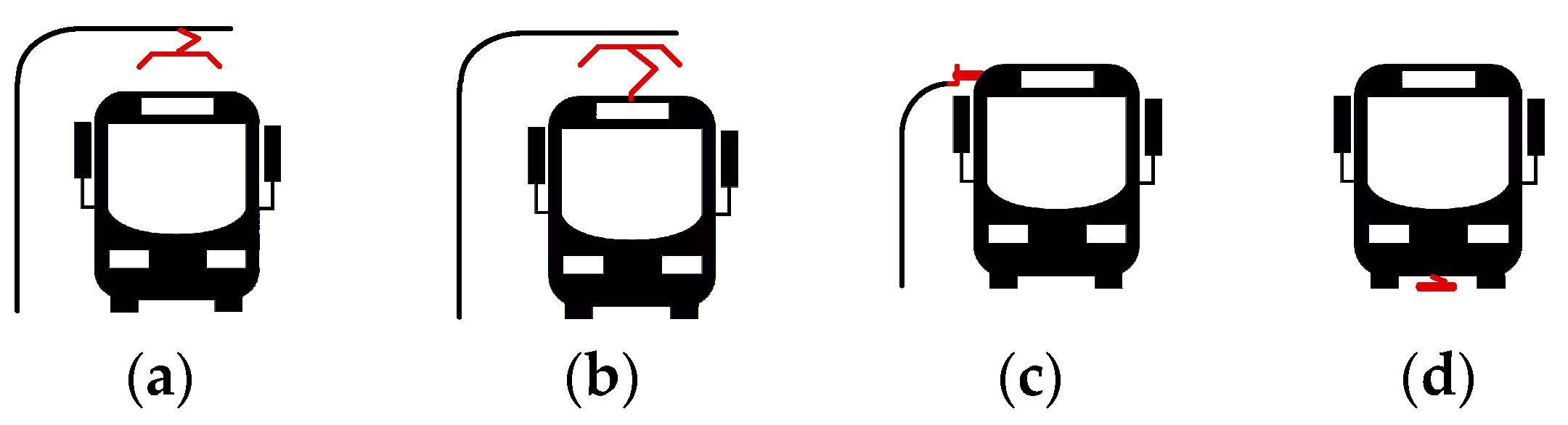
2. Charging Strategies and Methods for Electric Buses

Three main strategies are commonly used to charge e-buses: overnight or depot-only charging, in-motion or online charging, and opportunity or flash charging [11,20]. Buses using overnight-only charging possess huge batteries with high capacity (typically 200–500 kWh) which permits them to be used throughout the whole day without needing a recharge. These buses generally operate on shorter and less overcrowded routes (less than 100 km) [21]. The buses are charged using slow DC chargers with a plug-in cable interface (typically 50–150 kW). Online charging, on the other hand, allows buses to charge while moving. Opportunity charging describes a scenario whereby buses are not only charged at the depot but also when the bus stops at a bus stop (terminal stops and on-route intermediate stops), this process occurring throughout the day. The on-route chargers (Opportunity and Online chargers) allow buses to complete their routes with less battery capacity (typically 50–90 kWh), thus providing a more efficient system [22]; however, these chargers tend to be more expensive than depot chargers due to their high-power requirements (typically 150–450 kW) [7].
In terms of charging methods, there are four main options available, as seen in Figure 2: plug-in charging, pantograph charging, induction (or wireless) charging, and battery swapping [23,24,25]. Plug-in and pantograph charging are both referred to as conductive charging as conductors are used to transfer energy from the charging infrastructure to the e-bus. In plug-in charging, a connector or cable extending from the charging infrastructure is manually plugged into the bus to commence the charging operation. Inductive charging employs an electromagnetic field between a transmitting coil on the road surface and a receiving coil positioned at the bottom of the e-bus [26,27]. Pantograph charging, on the other hand, uses overhead connectors to automatically charge the bus.
They comprise four main types: downward (infrastructure-mounted or top-down or inverted) pantograph, upward (roof-mounted or bottom-up) pantograph, side insertion (horizontal) pantograph, and underbody pantograph, as shown in Figure 3 [28,29]. The upward pantograph is the easiest to implement technically, and the charging process is controlled/initiated by the driver; hence, there is no need for a Wi-Fi connection for communication. Its behavior is similar to a conventional Combined Charging System (CCS) plug. Communication is performed using the IEC 61851 and ISO 15118 protocol [30]. The downward pantograph, however, requires a Wi-Fi connection for communication between the pantograph and the bus, and this is performed using the OppCharge standard. The advantage of this pantograph variant is that the height of the bus is reduced, which enables it to pass under low-clearance bridges, and the weight of the system is reduced, which is especially helpful if the system is at its maximum weight limit. The functioning of the horizontal pantograph is like an inverted pantograph as the moving part is on the charging infrastructure side. Communication can be performed using either the ISO 15118 standard based solely on a pure conductive system without Wi-Fi or the OppCharge standard that uses Wi-Fi. The underbody pantograph is either set on the bus and connected to the infrastructure like a roof-mounted pantograph or placed on the ground and moved upward onto the bus like an inverted pantograph.
Battery swapping entails physically replacing a depleted battery pack with a charged battery. When compared to the previously mentioned conductive or wireless methods, the swapping process is extremely fast, typically taking only a few minutes using automatic robotic arms. Furthermore, the batteries at swapping stations could be used as grid support units, supplying power to the grid during peak periods and charging during off-peak periods [31]. Currently, there are some obstacles to implementing battery swapping, such as a very high initial setup cost and the requirement for massive storage space due to the need to store both discharged and fully charged batteries [32].
The choice of the best charging technique depends largely on the strategy you want to apply. Depot-only strategies require the least additional equipment. Additionally, the depot-only are the simplest solutions, and they are mainly plug-in. Instead, for opportunity charging, pantographs are most common. Induction charging is more expensive and more difficult to develop and apply than the other two alternatives.

3. Architectures and Converters Topologies for Fast Charging of Electric Vehicles and Electric Buses

In general, two main types of DC fast-charging architectures can be identified [33]: AC-bus architecture and DC-bus architecture, shown respectively in Figure 4a,b. As seen in Figure 4a, the AC-bus system uses a low-frequency step-down transformer to interface the distribution network with the three-phase AC bus. Each charging station requires a separate AC–DC rectifier; meanwhile, to interface RESs and ESSs to the AC bus requires additional DC–AC inverters. This approach, therefore, significantly increases the number of power electronic conversion stages linking the various elements together, which leads to increased system complexity, cost, and power losses, thereby reducing the overall efficiency [13]. The merits of using the AC-bus approach include the availability and maturity of the rectifier and inverter technology, availability of AC switchgear and protective devices, as well as well-established protocols/standards for AC power distribution systems.
The DC-bus system uses a low-frequency transformer for galvanic isolation and to step down the distribution system voltage. The resulting low voltage is fed to a central frontend AC–DC rectifier to create a common DC-bus voltage. As the number of power electronic conversion stages is reduced, this approach provides a more efficient way of interfacing DC energy storage systems and renewable energy sources. The main problem with this approach is the lack of DC protection schemes and standards [34].
There are two types of DC-bus systems, as illustrated in Figure 5: unipolar DC-bus and bipolar DC-bus. The unipolar DC-bus system employs a two-wire configuration, resulting in a single DC voltage level, and is typically used with two-level voltage source converters such as the Vienna converter, whereas the bipolar DC-bus system employs a three-wire configuration, resulting in two DC voltage levels, and is compatible with three-level voltage source converters such as the Neutral Point Clamped (NPC) converter. Even though the bipolar system has more design and control complexity than the unipolar system and requires voltage balancing algorithms, it is more flexible, resilient, and fault tolerant [35].
Several AC–DC and DC–DC converter topologies for fast charging of electric vehicles and buses have been proposed in the literature. To design the fast-charging station, we must choose the AC–DC and DC–DC converter that produces the best results in terms of system requirements from a menu of options. The following subsections describe the various grid-connected AC–DC converters and DC–DC converters that are commonly used for battery charging.

3.1. Front-End AC–DC Converters

These converters connect the three-phase AC grid to the DC bus. They must meet certain performance targets, such as high-power factor, sinusoidal input current (low harmonic distortion), regulated output DC voltage, EMI compliance, low complexity and cost, and continued operation if one phase fails [17,36]. The topologies depicted in Figure 6 appear to be promising for meeting the aforementioned requirements while operating at high power densities.
The topology shown in Figure 6a is the Vienna rectifier. It can only produce unidirectional power flows because of the presence of three-phase bridge diodes, making this topology unsuitable for V2G applications [37]. It has bidirectional switches arranged in a star pattern, with the neutral point connected to the center of two capacitors. As a result, it operates as a three-level boost converter, resulting in a smaller AC inductor. This converter has a controlled output voltage, low EMI, and reduced voltage stress on power switches as they are stressed with half the output voltage. It does, however, have a high control complexity, necessitates DC-link capacitor voltage balancing algorithms, and has limited reactive power control, limiting the power factor range [38,39].
To provide bidirectional power flow capability, the two-level voltage source six-switch boost rectifier depicted in Figure 6b can be used. This converter is the most widely used topology for grid interfacing because it has simple control, low THD, a wide range of power factor control at the AC side, and controllable DC-side voltage [39]. However, it has some demerits, such as a limited switching frequency, a large input inductor, high voltage stress of the semiconductor switches due to subjection to the full-scale DC-link voltage, and reduced reliability due to the possibility of a bridge leg shoot-through, which results in DC-bus short-circuiting [36]. Many control strategies, such as sinusoidal PWM, Space Vector Modulation (SVM), Sliding Mode Control (SMC), hysteresis current control, and One Cycle Control (OCC), have been proposed in the literature, all with the goal of reducing the size of the input filter and the stress on the power switches [19]. As shown in the figure, the maximum current through each semiconductor is equal to the maximum current in each phase of the AC grid. One possibility for lowering the maximum current through each power switch is to interleave the converters, as shown in Figure 6c, which depicts a bidirectional interleaved converter formed by connecting two of the converters of Figure 6b in parallel. This topology reduces the maximum current passing through each power switch due to the splitting of phase currents into two paths, but at the expense of more hardware components [37]. Furthermore, by interleaving both converters, harmonic cancellation in the input current waveform, as well as reduced DC side voltage oscillations, are possible [40]. The size of the input boost inductance is significantly reduced due to the interleaved converter’s frequency doubling characteristics. Circulating currents between the two paralleled rectifiers are a major concern in this topology because additional conduction pathways appear when these converters are connected to the same DC-bus and common sources [41].
It is possible to use a multilevel converter topology to further reduce voltage stress on semiconductor voltage switches. The NPC converter shown in Figure 6d, which represents a three-level converter, is the most used multilevel configuration. This converter allows bidirectional power flow and generates a controllable DC voltage with a magnitude greater than the peak input voltage. It also enables the use of lower voltage semiconductor devices while operating at a lower switching frequency [42]. Other characteristics of this converter include its very low THD in input line current, small passive filtering requirements, and explicit creation of a bipolar DC-bus, which has been investigated by [43] to implement a charging station, allowing DC–DC converters to connect to half of the DC-bus voltage [34]. The requirement for capacitor voltage balancing algorithms [44,45] is one of the most difficult challenges associated with the use of this converter. If the voltage drops across the capacitors are left unbalanced, it may result in poor output voltage quality, affecting control performance or even causing semiconductor devices to fail [46].
The six-switch current-source buck converter shown in Figure 6e is another common PFC rectifier used in charging stations. This converter can only produce unidirectional power flow if the output DC voltage polarity is fixed. However, if the polarity of the output DC voltage could be inverted or reversed, bidirectional power flow is a distinct possibility [34]. Furthermore, unlike the Vienna rectifier, this converter lacks a center point, so no capacitor voltage balancing is required. Moreover, because of its buck nature, it can exhibit low semiconductor voltage stress while also providing short-circuit protection [36]. However, it has relatively high conduction losses since there are more series-connected devices, and it presents pulsating input currents, requires EMI filtering, and offers limited power factor range control at the AC, which results in a reduced output voltage control range [47].
Figure 6f depicts a Swiss rectifier proposed by [48] and later by [49] as a possible candidate for level-III battery charging of electric vehicles and buses. It uses two buck converters to control the output voltage to be less than the peak input voltage, eliminating the need for AC filter inductors [50]. It uses the third harmonic current injection principle to achieve a purely sinusoidal input current. Other characteristics of this converter include low current stress on the power transistors, which leads to high efficiency, low control complexity, and short circuit current limiting capability [36,51]. Additionally, it has more active power switches than the six-switch buck converter. Aside from that, the capacitor filters on the AC side result in significant reactive power consumption. This converter can only produce unidirectional power flow; however, various researchers have worked on modifications to this converter to produce bidirectional power flow [52,53,54,55].
The 12-pulse thyristor bridge rectifier shown in Figure 6g is another grid-facing converter that can produce a regulated DC voltage. It employs a multi-winding transformer with Y–Y and Y–Δ connections and proper turn ratios to realize two three-phase voltage sources with the same amplitude at a 30-degree phase shift. By connecting two six-pulse thyristor bridge rectifiers, a total of 12 pulses per cycle are produced at the output [50]. This significantly reduces the current harmonics and makes the input current more sinusoidal. The disadvantage of this approach is that it necessitates the use of a multi-winding transformer, which is bulky and heavy, and only produces unidirectional power flow. Furthermore, because the traditional 12-pulse rectifier does not meet the IEEE 519 standard of producing THD of less than 5%, additional passive or active filters must be connected at the input, which are typically heavy and bulky and may reduce the circuit’s power factor [56]. Many studies have been published in the literature aimed at lowering the input current THD to less than 5% by modifying the conventional 12-pulse rectifier of Figure 6g [57,58,59,60]. The outputs of the two six-pulse rectifiers could be connected in series or parallel, with the parallel connection being preferred for high-current applications because it has a lower thyristor forward voltage drop despite some current sharing issues [56]. Of all the AC–DC converters described so far, this is the least used converter for EV charging.

3.2. Back-End DC–DC Converters

The main objective of the DC–DC converter is to regulate the output voltage from the front-end AC–DC converter to a level that is sufficient to charge the EV battery in the desired mode (constant current, or constant voltage). It also provides an interface for the connection of Renewable Energy Sources (RES) and Energy Storage Devices (ESD). DC–DC converters could be split into two main groups: isolated and non-isolated. The isolated DC–DC converters shown in Figure 7 contain a high-frequency transformer and are required to provide galvanic isolation between the grid and the battery or ESS. On the other hand, the non-isolated DC–DC converters shown in Figure 8 need to be interfaced with a bulky low-frequency transformer at the grid side to provide protection.

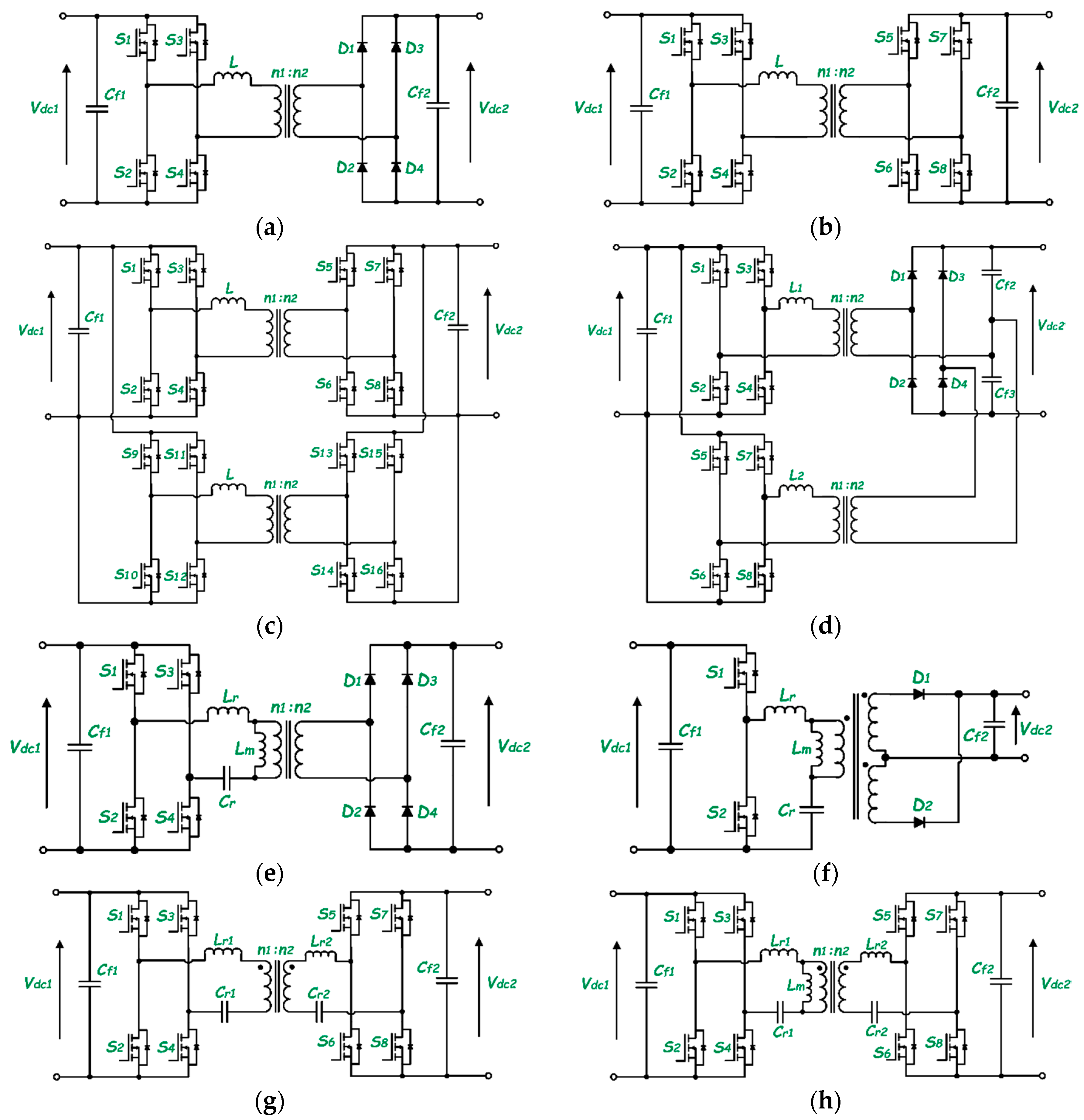
3.2.1. Isolated DC–DC Converters

The most popular topology used for high power and high frequency applications is the Phase-Shift Full-Bridge (PSFB) converter shown in Figure 7a. This converter has a simple control system; low current stress on the power switches, as it receives a Zero Voltage Switching (ZVS) using the leakage inductance of the transformer in addition to the parasitic capacitance of the power switches; and a wide range of output voltages [61]. However, the converter has some demerits, such as unidirectional operation, duty cycle losses in active switches, hard-to-achieve ZVS at light load (limited ZVS range), high conduction losses in output diodes, circulating current losses, and high voltage ringing on the secondary side rectifier diodes [62], which could be reduced using passive or active snubber circuits, but this reduces the system efficiency [34].
To provide bidirectional conduction capability, the Dual Active Bridge (DAB) schematic seen in Figure 7b could be used, formed by replacing the diodes in the previous circuitry with MOSFETs. Just like the previous topology, this converter also provides a wide output voltage range and has soft-switching capability. Compared to the converter in Figure 7a, this topology has lower voltage stress on the switches, provides higher power densities, and has better efficiency [36]. Despite the advantages, it also possesses some setbacks, such as the presence of reactive current, large input, and output ripple due to switching, hence the need for large input and output filter [63] and hard switching at light load [64].
The performance of the DAB could be improved by interleaving it, as shown in Figure 7c. This allows a reduction in the operating power of each DAB [37], reduces the voltage and current ripple in the input and output capacitors, and reduces input and output filtering requirements, all these at the cost of more hardware and an increase in control complexity.
Another unidirectional converter proposed by the authors of [65] that could be used for battery charging is the isolated interleaved DC–DC converter with a voltage doubler shown in Figure 7d. When operating in Discontinuous Conduction Mode (DCM) and Boundary Conduction Mode (BCM), this converter has no reverse recovery losses in the secondary rectifier diodes and no high voltage ringing, which is usually caused by resonance between the diode parasitic capacitance and the transformer leakage inductance. Interleaving the converters reduces ripple current and voltage stress on the output filter capacitors [66]. Interleaving also has the advantage of distributing thermal losses uniformly among the cells while sharing equal power. Furthermore, the input ripple is four times the switching frequency [67], the number of secondary diodes can be considerably reduced with the output voltage doubler rectifier, and the diode voltage rating is equal to the maximum output voltage. The disadvantage of this converter is that its operation in Continuous Conduction Mode (CCM) results in the lowest RMS currents. Additionally, while ZVS can be achieved for all switches, high di/dt results in large reverse recovery losses in the secondary side rectifier diodes and high voltage ringing. Moreover, CCM operation necessitates the use of a large resonant inductor, which raises the transformer turns ratio, increasing the stress on the primary side switches [68].
Another popular category of DC–DC converters for use in fast charging is the LLC resonant converter which is of two main types: full-bridge LLC converter shown in Figure 7e and half-bridge LLC converter shown in Figure 7f. The full-wave rectification process at the secondary side could be performed using either a full bridge rectifier, as shown in Figure 7e, or a center-tapped transformer, as shown in Figure 7f. In general, the choice between full-bridge and half-bridge on the primary side is determined by the power level, with full-bridge architecture being preferred for high power applications and half-bridge configuration being preferred otherwise, whereas the choice between center tap and full-bridge on the secondary side is determined by the current and voltage levels, with center tap being preferred for low voltage and high current applications and full-bridge being used otherwise [69]. In these converters, all the semiconductors are soft switching, i.e., ZVS takes place at turn-on for the primary MOSFETs and ZCS at both turn-on and turn-off for the diode rectifiers in the secondary [70]. In comparison to other resonant converters, these topologies have high efficiency at high input voltage; their primary switches can operate at ZVS over a wide range of loads, there are no reverse recovery losses on secondary diodes, and there is low voltage stress on the rectifying diodes. The main issue with these converters is that they require a wide range of switching frequencies to be applied to control the output voltage [71,72]. The wide range of switching frequencies creates complications in the design of circuit filters, transformer magnetics, and gate driver circuits, brings about poor EMI performance, and causes a loss of soft switching at some frequency of operation, resulting in low efficiency of power conversion [73,74,75,76]. The converters shown provide only unidirectional power flow, and thus cannot be used for V2G applications. Bidirectional power flow is possible if the diodes are replaced with MOSFETs in a synchronous rectification process.
Although the LLC resonant converter can be configured to provide bidirectional power flow, this causes several issues. The magnetizing inductance of the transformer is clamped by the output voltage during reverse power flow conditions, excluding it from the resonance process. In this case, the LLC resonance circuit operates similarly to an LC series resonance circuit with a maximum voltage gain of one. As a result, ZCS is impeded at the rectifier side, lowering converter efficiency dramatically [77,78]. To address this issue, the full-bridge CLLC symmetric resonant circuit shown in Figure 7g is frequently used in bidirectional power flow applications. During reverse power flows, this converter can simultaneously achieve ZVS on the supply side and ZCS on the rectifier side, reducing switching energy losses and increasing overall circuit efficiency. Furthermore, the range of bidirectional DC gains is expanded, resulting in greater voltage regulation flexibility [79]. The performance of the CLLC resonant circuit can be improved by either interleaving the converter, as performed in [80], which increases the volume and cost of the design, or by adding the magnetizing inductance of the transformer to form a CLLLC resonant circuit [81,82,83], as shown in Figure 7h. However, this increases the converter’s design complexity.

3.2.2. Non-Isolated DC–DC Converters

This part of the paper focuses on the performance analysis and characteristics of the most used non-isolated DC–DC converters that could be employed for charging electric vehicles and integrating energy storage systems to the DC-link.
For battery charging, a traditional single-phase buck converter could be used to step down the DC-link voltage to a voltage that is acceptable by the battery. However, for this design, either a large inductor is used to reduce the inductor current ripple to small values, which increases the cost and size of the converter, or the switching frequency is increased to improve the dynamic performance of the converter, but this increases the switching losses [61,84]. A solution to this is to interleave two or more of the converters to form a multi-phase interleaved buck converter [85,86,87,88].
Figure 8a shows an example of a two-phase interleaved buck converter. Interleaving the converter brings about current splitting, which results in current ripple cancelation, better thermal performance, possible reduction in conduction losses, higher efficiency, and higher power density [66]. Additionally, the size and ratings of the inductor and filters decrease as the fundamental frequency of each inductor is multiplied by the number of phases. In this converter, the drive signals of the active switches must be phase-shifted by 360°/N, where N is the number of phases [89]. Similar interleaving configurations are possible with boost and buck–boost converters.
Figure 8b depicts a three-level NPC bidirectional converter that operates in buck mode for G2V and boost mode for V2G. This converter is used in high input voltage, high power, and high switching frequency applications because the stress on the switches is only half of the DC bus voltage, allowing lower voltage rating switches to be used, as opposed to two-level converters, which are rated for the full-scale DC-link voltage [90,91,92]. As a result, the converter’s effective switching frequency is doubled [93]. Furthermore, the filter inductor can be significantly reduced, resulting in a fast dynamic response [94]. Moreover, this converter is compatible with any charging station having a bipolar DC-bus [95], and the authors of [96] have taken advantage of this property. This converter, however, has some drawbacks, including its unsuitability for interleaving due to the formation of circulating currents [97], its voltage conversion ratio being the same as that of a two-level buck/boost converter, and its input and output terminals not being commonly grounded, which increases ElectroMagnetic Interference (EMI) [93].
To address the problems associated with voltage gain and the lack of a common ground found in the previous converter, [94] proposed the three-level flying capacitor bidirectional converter shown in Figure 8c. This converter has a high voltage conversion ratio with improved efficiency; low inductor core and copper losses; low input current ripple, resulting in a smaller input filter; and low voltage stress on power switches [98]. The disadvantage of this converter is that the voltage of the flying capacitors in each stage must be balanced to their nominal value, increasing the circuit control complexity [99]. If the flying capacitor voltage remains unbalanced, the voltage stress on the switches increases, potentially resulting in power loss [100]. Many capacitor voltage balancing techniques have been mentioned in the literature, with active and passive voltage balancing (RLC filter) being the most notable [101,102,103].
The cascaded buck–boost converter shown in Figure 8d is another non-isolated bidirectional DC–DC converter proposed by [104] that is commonly used in charging stations and energy storage systems. This is a four-quadrant converter, so it can operate in buck and boost modes in both directions [105,106]. The switches have lower electrical and thermal stresses than traditional buck–boost converters and can achieve ZVS without the use of an additional or auxiliary soft switching circuit by employing appropriate modulation strategies [107]. It does, however, have complex control strategies and suffers from some turn-on losses due to the reverse recovery problem of transistor body diodes when the conventional PWM strategy is used while operating in CCM, which reduces efficiency [108]. Hard switching reduces efficiency even further when operating under light load conditions [109].
The split-pi bidirectional converter topology of Figure 8e is a relatively new topology among other DC–DC converters, having been patented by Timothy Richard Crocker in 2002 [110]. This converter is widely used in electric mobility, battery management, energy storage, and interfacing renewable energy systems. It is made up of two interconnected DC–DC converters that share a common DC-link and have two independent DC interfaces that are used to generate an output voltage that can be higher, equal, or lower than the input voltage, making it a four-quadrant converter [111]. This converter has a wide range of operational modes and employs small-sized passive components. Furthermore, only one bridge switch is switched at a time, reducing voltage stress on the switches [112]. Moreover, because of its topological configuration, it has lower switching losses, distortions, and ripples on output current, resulting in efficiencies of over 97% [113,114]. One issue with this converter is that during operation, the voltage gain of one of the stages is set to unity, causing the other converter stage to act as a second-order filter in the forward path, potentially introducing phase delays and complicating the system’s feedback control [115]. Paralleling this converter, as shown in Figure 8f, reduces current ripples in the input and output currents even further [116].
Another popular converter is the bidirectional Cuk converter shown in Figure 8g, which is derived from the conventional unidirectional Cuk converter by replacing the main diode with a MOSFET. This converter is essentially a boost converter followed by a buck converter; thus, it can step up or step down input voltage like a traditional buck–boost converter [117]. In contrast to other topologies that use inductors to store energy, the transfer capacitor (Ct) is used as the energy storage component. When compared to the cascaded buck–boost and traditional buck–boost converters, this converter is a better choice for interfacing energy storage systems and charging EV batteries because it produces fewer current ripples at the input and output [118]. If the inductors L1 and L2 are coupled, the input and output current ripples can be further reduced [106]. This converter has some drawbacks, such as reverse voltage polarity at the output, the need for large-sized inductors, and high voltage stress (Vin + Vo) on the transfer capacitor [117,119].
To overcome the drawbacks of the bidirectional Cuk converter discussed above, the SEPIC/zeta converter shown in Figure 8h, which is simply a rearrangement of the Cuk converter, can be used. It can operate as a buck or boost converter in both directions and generates an output voltage with the same polarity as the input [120]. For positive power flows, the converter acts as a SEPIC converter, and for negative power flows, it acts as a zeta converter [106]. The voltage stress on the transfer capacitor in this case is simply Vin. This converter supports a wider range of input voltages than the Cuk converter and has lower current and voltage ripples, which can be further reduced if the inductors are coupled [121]. With the addition of auxiliary circuits, soft switching can be achieved in this converter [122]. The converse of the SEPIC/zeta converter is the Zeta/SEPIC converter, which has also been used for battery charging and energy storage systems [123,124].
Different control methods are mentioned in the literature to control the converter power, and thus currents and voltages, which are used to effectively manage the battery charging of these e-mobility systems. Model Predictive Control (MPC) is used in [125] for current control, fault detection, and State of Charge (SoC) balancing of all split battery storage at the same rate. Aside from MPC control, the traditional Proportional–Integral (PI) control strategy is frequently used, as in [126,127]. In [126], the authors implement a three-phase off-board charger and use PI controllers to perform decoupled dq grid current control and DC-link voltage control, as well as independent battery current control with PI and the integration of duty ratio feedforward control to achieve rapid dynamic control. Refs. [128,129] have also implemented more advanced control techniques such as Sliding Mode Control (SMC). The authors of [128] use SMC in aircraft battery charging to overcome the stability issues encountered by traditional PI controllers when used for multi-objective controls, whereas the authors of [129] use SMC in LLC converters to improve dynamic response and robustness at the expense of increased complexity in the design and parameter tuning process. In [130], second-order Linear Active Disturbance Rejection Control (LADRC) is used for LLC resonant converter to improve dynamic performance and suppress the influence of internal and external disturbances on output battery voltage.

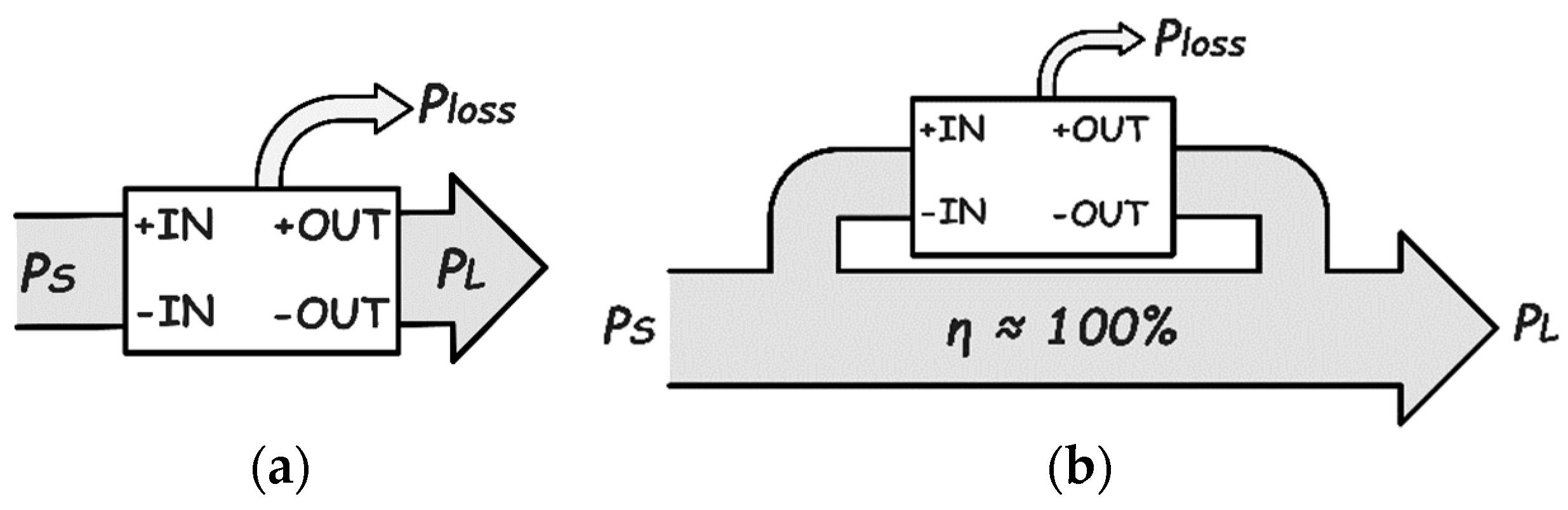
4. DC–DC Converters Based on Partial Processing of Power

So far, all the DC–DC converters discussed in the previous section are meant to process the complete power which comes in from the source, as shown in Figure 9a. If somehow only a fraction of the source power can go through these converters as shown in Figure 9b, while the rest of the power is directly sent to the load, then the conduction, switching, and magnetic losses will be reduced, and the global efficiency of the converter will be increased [131,132]. This is the idea behind the concept of power converters based on partial processing of power, otherwise known as Reduced Dissipation Converters (RDCs). Aside from the increase in system efficiency, this configuration has other merits like a reduction in converter ratings as a result of reduced voltage stress, small-sized converters can be used, as well as a reduction in the overall cost of the system [133]. This concept is relatively new and has been applied in a variety of applications including distributed PV systems [134], electric vehicle fast-charging stations [135,136,137], fuel cell-powered hybrid electric vehicles [138], and current control in battery energy storage systems [139]. The downside of this type of architecture is that the galvanic isolation between the source and load is bridged since power has to directly flow from the source to the load and is therefore actively being researched.
Partial processing converter (PPC) architectures mainly comprise two types: those that require isolated DC–DC converters, as shown in Figure 10, and those that do not require isolated DC–DC converters, as shown in Figure 11 [140,141,142,143].
For these converters, the parameter that defines the amount of power processed by them is known as the active power ratio (Kpr) and is defined as:
K p r = P p c P s
where Ppc and Ps are, respectively, the power processed by the converter and the source power. The converter works in PPC mode only if the partial power ratio Kpr < 1. As an example, we can compute the Kpr of the architecture in Figure 10a. The first thing is to apply Kirchhoff’s voltage and current laws to the architecture, as defined in Equations (2) and (3), and then compute the system efficiency as in (4):
V L = V S + V o u t
I S = I P C + I L
η s y s = V L * I L V S * I S
From (1), we receive
K p r = P p c P s = V o u t * I L V S * I S
By inserting Equations (2)–(4) into (5), we can receive Kpr as a function of the converter static voltage gain ( G V = V L / V S ) as given in (6).
K p r = η s y s ( 1 1 G V )
By using a similar technique, the Kpr of other architectures in Figure 10 can be derived, shown in Table 2.
In [144], the PPC shown in Figure 12b, which is based on an isolated DAB, was implemented for the fast charging of electric vehicles. This converter is based on the configuration of Figure 10d. Some of the results obtained are shown in Figure 13.
Figure 13a shows that the DAB-FPP processes 100% of the source power at all times during the charging process, whereas the DAB-PPP processes approximately 40% of the input power, which decreases as the battery state of charge increases. As a result, for SoCs greater than 5%, the DAB-PPP has a higher system efficiency, as shown in Figure 13b.
The use of PPC technologies for electro-mobility systems is quite promising, and future charging stations are expected to use this concept. However, proper isolation mechanisms must be researched before this system can be commercialized.

5. Power Converters for Electrified Railway Systems

Today, the demand for a reliable and safe high-speed electrified railway for mass public transportation is rising globally [145]. Compared to other modes of transportation, these electric railway systems are the most efficient and produce the least CO2 [146]. The safety, flexibility, and reliability of these railway systems have been further improved by recent developments in power electronic converters. Currently, traction motor controls, reactive power compensation, voltage compensation, auxiliary power supplies, regenerative braking, and main catenary power supply systems are just a few of the applications for power electronic converters in the railway industry [147]. However, we will only discuss the use of power electronics in railway power supply systems and traction drives.

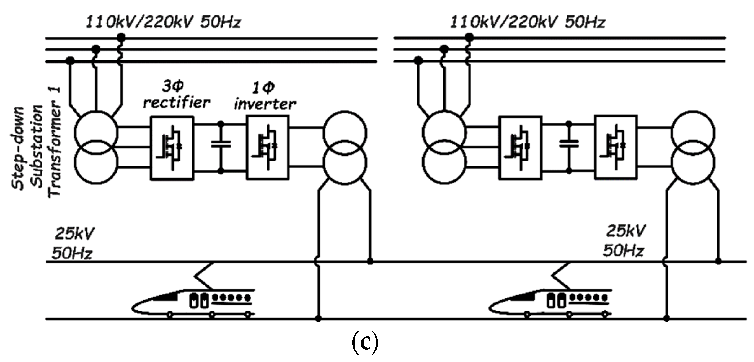
5.1. Power Supply Systems

For railway systems with an AC traction power supply system, the catenary voltage is usually single-phase, with RMS values of 15 kV at 16.7 Hz or 25 kV at 50/60 Hz being the most common. Additionally, depending on the country, a catenary voltage of 27.5 kV is also common. The single-phase catenary voltage is generally obtained from the three-phase distribution grid using transformers.
Figure 14a depicts the traditional power supply system. A transformer in the traction substation converts three-phase grid voltage to two-phase voltage. Scott and V/V transformer topologies are the most common in this type of application, though Leblanc transformers can also be found in some publications [148]. However, due to differences in the phase, amplitude, and frequency of the voltage between the adjacent arms α1 and β1 (α2 and β2), Neutral Sections (NS) emerge in one SubStation (SS) and between the adjacent substations (catenaries fed by different power substations). The presence of neutral sections causes power quality issues, such as power unbalance, the need for reactive power compensation, and low-order harmonics, which affect the power factor [149]. Furthermore, the neutral section causes a disturbance between the locomotive and the network, as well as a loss of locomotive speed. Additionally, NS makes new concepts like renewable energy or regenerative braking difficult to integrate [146].
To address the shortcomings of the traditional power supply system, compensator-based power electronic technologies for improving power quality in railway traction power systems have been proposed [150]. Figure 14b illustrates a co-phase traction power supply system using Active Power Compensation (APC). APCs can balance active power between the traction transformer’s two secondary windings, compensate for reactive power, and filter harmonics. Although the NS at the substation’s exit is eliminated in the co-phase system, the one between adjacent SS remains, making it difficult to connect all catenaries from different substations. This NS results from the inability to control the voltage frequency, phase, and amplitude of adjacent transformers [151]. Therefore, the number of NSs is half that of the traditional topology.
An advanced co-phase power supply system based on a three-phase to single-phase power electronic converter has been proposed in [152] to link all catenaries from different substations, removing all NS. As shown in Figure 14c, the traction substation has a step-down transformer and a step-up transformer on the input and on the output sides, respectively. As seen, the three-phase converter rectifies AC power from the grid into a DC-link capacitor, and the one-phase converter reverses DC power to single-phase AC power, which is then fed to the catenary. In this way, the system transfers active power from the isolated three-phase grid to a one-phase traction line and generates an output voltage with a controlled frequency, phase, and amplitude. Based on an appropriate control strategy of the single-phase converter, the amplitude and phase of the output voltage of each substation can be guaranteed to be the same [153]. Thus, the feeder line between different substations can be connected directly.
In the literature, several converter topologies have been used to implement the three-phase to single-phase power conversion, including the traditional two-level three-phase voltage source converter [151], three-level neutral point clamped [154,155,156,157], and the Modular Multilevel Converter (MMC) [158,159,160,161]. Among all the converter options available, the MMC is the most used due to its low output voltage harmonics, low switching losses, ease of expansion and capacity enhancement, no need for filters and large DC link capacitors, fault-tolerant ability, and low EMI [162]. The MMC is also known for its high voltage blocking capacity and reduced stress on the switching devices making up the different sub-modules.

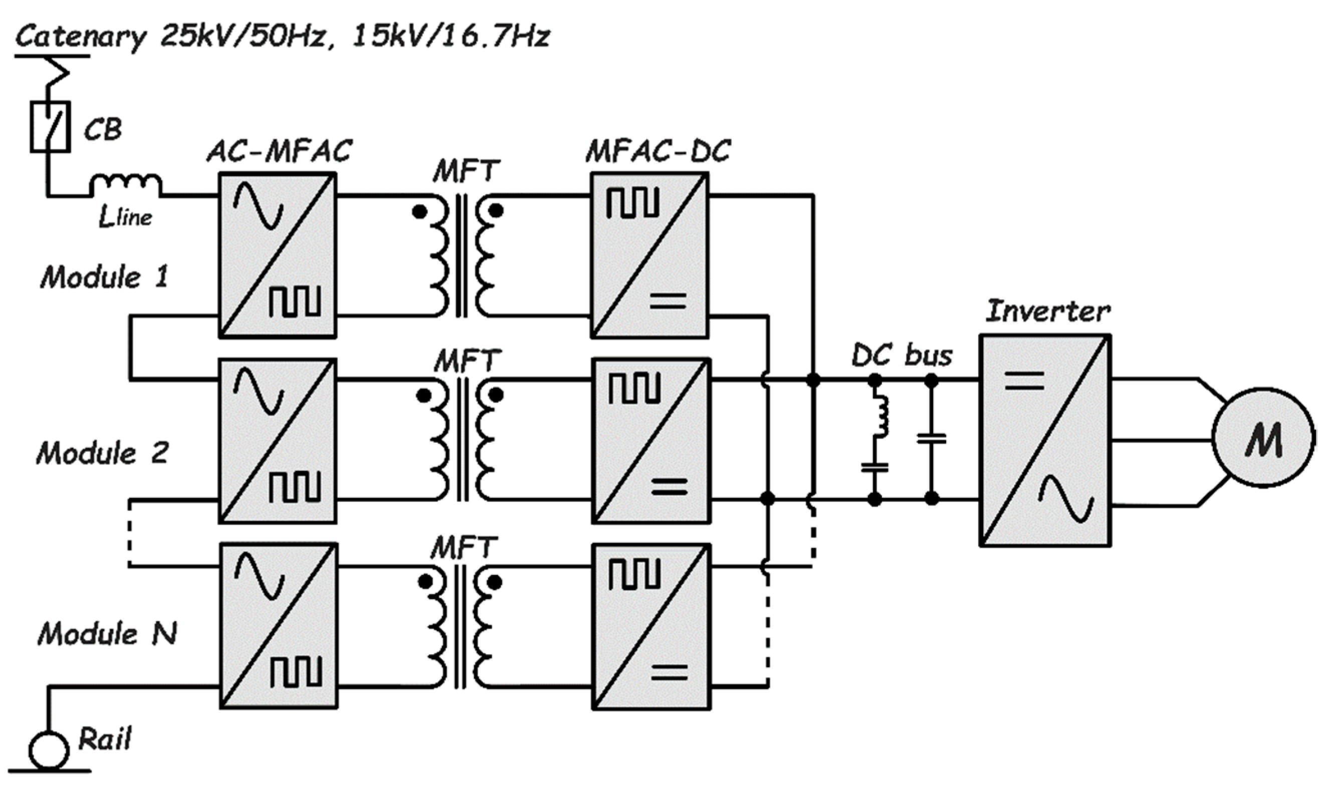
5.2. Traction Drives

Figure 15 depicts a conventional schematic of a traction drive for railway vehicles [163]. It is made up of a Line Frequency Transformer (LFT) whose primary winding is directly connected to the AC catenary voltage, which typically operates at 15 kV/16.7 Hz or 25 kV/50 Hz. The secondary winding supplies a stepped-down AC voltage (600 V to 2 kV RMS) to a rectifier, which generates the DC voltage required for the three-phase traction motor drive. Although this configuration is simple and reliable, it has some drawbacks, such as the LFT’s heavy and bulky nature, inability to control power factor, limited power density (0.25–0.35 kVA/kg), and relatively low efficiency (around 94% for 25 kV/50 Hz traction systems and 89–92% for 15 kV/16.7 Hz traction systems) [164].
As an alternative to the LFT, power electronic transformers (PET), also known as Solid-State Transformers (SST), have been proposed and widely used to increase the power density (0.5–0.75 kVA/kg) and efficiency of railway vehicles. These transformers operate at very high switching frequencies, allowing them to be much smaller and lighter than their LFT counterpart [165]. They also offer fault isolation, reactive power compensation, voltage regulation, power flow control, voltage sag compensation, bi-directional power flow, fault current limiting, and harmonic blocking [166]. Despite the benefits of SST-based electric railway drive systems, they are more expensive and difficult to control than LFT-based ones.
Due to converter unit voltage rating limitations, several converter stages must be cascaded to meet the voltage and power requirements of the SST-based motor drives. These converters can be cascaded in two or three stages, as illustrated in Figure 16 and Figure 17, respectively.
The two-stage cascaded PET topology has been successfully utilized by the authors of [167,168,169]. Ref. [167] proposes a single-phase AC/AC MMC topology with submodule voltage balancing schemes. Section VII-A discussed the advantages of the MMC topology over other topologies. In [168], the AClf/ACmf conversion is accomplished via cycloconverters (matrix converters). The authors use transformer leakage and magnetizing inductance to achieve natural cycloconverter commutation and soft switching of a single-phase inverter, respectively. They also claim that such a configuration provides lower losses and good EMC behavior due to the switches’ low dv/dt and di/dt values. Finally, ref. [169] proposes a current source PET-based traction system comprised of front-end and output full-bridge converters, as well as a high-frequency fly-back inductor (transformer) that provides galvanic isolation and voltage adaptation. However, complicated voltage balancing of the input side series-connected capacitors, which work only in steady-state, is required.
As with the two-stage cascaded PET configuration, several works based on the three-stage PET topology have been reported, as demonstrated by Zhao et al. [170] and Shu et al. [171]. The first stage in [170] employs a two-level voltage source rectifier, which is followed by a half-bridge LLC resonant converter that enables soft switching and high switching frequencies. Furthermore, the PET’s full and half-bridge circuits enable bidirectional power flow, allowing for regenerative braking on railway vehicles. The system was stacked in nine levels and demonstrated a 96% efficiency while producing a maximum power of 900 kW that could be increased to 1.8 MW during short periods of acceleration and braking. [171] proposes and validates a three-level diode-clamped PET-based traction drive system composed of a single-phase cascaded three-level H-bridge AC–DC rectifier and a half-bridge three-level DC–DC converter. When the input and output voltages are 100 V and 70 V, respectively, the system produces 100 W without any layer-stacking, which would have to be considered in practical situations. The main disadvantage of this topology is that unbalanced capacitor voltages are quite common, necessitating capacitor voltage balancing. Furthermore, the switches have unequal thermal stress distribution, which increases losses.

6. Conclusions

Even though electric buses equipped with batteries have many features better than their diesel counterparts, there are some problems that public transportation companies need to solve for their mass deployment. The absence of adequate charging infrastructure, especially in small towns, and the short driving range are only two of the issues that are limiting the large-scale deployment of these vehicles to some extent. Then, among the challenges to be faced in the near future for the development of battery-powered electric buses, there is certainly the development of an adequate infrastructure for charging them. A key challenge is the integration in the electric distribution system of sustainable sources as photovoltaic plants. Recently, many researchers are focusing on this issue [172].
Beyond the logistic issues, there are those related to the power electronics needed for charging the batteries of e-buses and electric trains. Advances in the development of Wide Band Gap (WBG) semiconductor devices for power electronics have made this target a real possibility with many high-energy efficient electric transport systems now available commercially. Despite the importance of power electronic systems in achieving an electrified transportation system, their integration into the AC power grid causes a lot of power quality issues like voltage and power instabilities, that, even if studied for many years, still need to be addressed.
Throughout this work, we have painstakingly reviewed all the major aspects of modern-day power electronic converters that are commonly used in the fast charging of electric cars and buses, as well as the various converter topologies commonly used in railway systems. Much research is currently being conducted to develop new vehicle fast-charging infrastructures that can meet the power demands of various car owners in a matter of minutes. Power supply to electric trains, which still have a lot of power quality issues and grid disturbances, is equally important and under serious research. All these are feasible because of recent advancements in wideband gap technologies, which have allowed converters to significantly improve in power density, efficiency, cost, size, and reliability (lifetime).
It is hoped that this work will serve as a starting point for electrical and electronic engineers in the energy and automotive industries or related fields to make design-related decisions such as the best connection scheme if hybridized, and the choice of power converter topology for battery charging systems.

Author Contributions

Conceptualization, A.A.N., P.C. and N.D.; investigation, A.A.N.; writing—original draft preparation, A.A.N. and N.D.; writing—review and editing, P.C., N.D., E.S. and E.C.; supervision, N.D. and P.C. All authors have read and agreed to the published version of the manuscript.

Funding

This research was funded by “Ministero dell’Istruzione, dell’Università e della Ricerca—Programma Operativo Nazionale 2014-2020 (PON): AZIONE IV.5—Dottorati su tematiche Green del PON R&I 2014-2020”.

Data Availability Statement

No new data were created.

Conflicts of Interest

The authors declare no conflict of interest.

References

  1. Coal and Lignite Production. Available online: https://yearbook.enerdata.net/coal-lignite/coal-production-data.html (accessed on 11 December 2022).
  2. Crude Oil Production. Available online: https://yearbook.enerdata.net/crude-oil/world-production-statistics.html (accessed on 11 December 2022).
  3. Natural Gas Production. Available online: https://yearbook.enerdata.net/natural-gas/world-natural-gas-production-statistics.html (accessed on 11 December 2022).
  4. Boehm, S.; Lebling, K.; Levin, K.; Fekete, H.; Jaeger, J.; Waite, R.; Nilsson, A.; Thwaites, J.; Wilson, R.; Geiges, A.; et al. State of Climate Action 2021: Systems Transformations Required to Limit Global Warming to 1.5 °C; World Resoursec Institute: Washington, DC, USA, 2021. [Google Scholar]
  5. European Commision. The European Green Deal: Communication from the Commission to the European Parliament, the European Council, the Council, the European Economic and Social Committee and the Committee of the Regions; European Commision: Brussels, Belgium, 2019.
  6. Verbrugge, B.; Hasan, M.M.; Rasool, H.; Geury, T.; El Baghdadi, M.; Hegazy, O. Smart Integration of Electric Buses in Cities: A Technological Review. Sustainability 2021, 13, 12189. [Google Scholar] [CrossRef]
  7. Elma, O.; Gabber, H.A. Flywheel-Based Ultra-Fast On-Route Charging System for Public E-Buses. In Proceedings of the 2nd International Conference on Electrical, Communication and Computer Engineering (ICECCE 2020), Istanbul, Turkey, 12 June 2020; pp. 12–13. [Google Scholar]
  8. Osieczko, K.; Zimon, D.; Płaczek, E.; Prokopiuk, I. Factors That Influence the Expansion of Electric Delivery Vehicles and Trucks in EU Countries. J. Environ. Manag. 2021, 296, 113177. [Google Scholar] [CrossRef] [PubMed]
  9. Acri, R.A.; Barone, S.; Cambula, P.; Cecchini, V.; Falvo, M.C.; Lepore, J.; Manganelli, M.; Santi, F. Forecast of the Demand for Electric Mobility for Rome–Fiumicino International Airport. Energies 2021, 14, 5251. [Google Scholar] [CrossRef]
  10. Deb, S.; Kalita, K.; Mahanta, P. Impact of Electric Vehicle Charging Stations on Reliability of Distribution Network. In Proceedings of the 2017 IEEE International Conference on Technological Advancements in Power and Energy: Exploring Energy Solutions for an Intelligent Power Grid, TAP Energy 2017, Kollam, India, 21–23 December 2017; Volume 1, pp. 1–6. [Google Scholar]
  11. Steen, D.; Tuan, L.A. Fast Charging of Electric Buses in Distribution Systems. In Proceedings of the 2017 IEEE Manchester PowerTech, Powertech 2017, Manchester, UK, 18–22 June 2017. [Google Scholar]
  12. Pothinun, T.; Premrudeepreechacharn, S. Power Quality Impact of Charging Station on MV Distribution Networks: A Case Study in PEA Electrical Power System. In Proceedings of the 2018 53rd International Universities Power Engineering Conference (UPEC), Glasgow, UK, 4–7 September 2018; pp. 1–5. [Google Scholar] [CrossRef]
  13. Tahir, Y.; Khan, I.; Rahman, S.; Nadeem, M.F.; Iqbal, A.; Xu, Y.; Rafi, M. A State-of-the-Art Review on Topologies and Control Techniques of Solid-State Transformers for Electric Vehicle Extreme Fast Charging. IET Power Electron. 2021, 14, 1560–1576. [Google Scholar] [CrossRef]
  14. Urcan, D.C.; Bica, D. Integrating and Modeling the Vehicle to Grid Concept in Micro-Grids. In Proceedings of the 2019 International Conference on ENERGY and ENVIRONMENT (CIEM), Timisoara, Romania, 17–18 October 2019; pp. 299–303. [Google Scholar] [CrossRef]
  15. Khalid, M.R.; Alam, M.S.; Sarwar, A.; Jamil Asghar, M.S. A Comprehensive Review on Electric Vehicles Charging Infrastructures and Their Impacts on Power-Quality of the Utility Grid. eTransportation 2019, 1, 100006. [Google Scholar] [CrossRef]
  16. Khalid, M.R.; Khan, I.A.; Hameed, S.; Asghar, M.S.J.; Ro, J.S. A Comprehensive Review on Structural Topologies, Power Levels, Energy Storage Systems, and Standards for Electric Vehicle Charging Stations and Their Impacts on Grid. IEEE Access 2021, 9, 128069–128094. [Google Scholar] [CrossRef]
  17. Turksoy, O.; Yilmaz, U.; Teke, A. Overview of Battery Charger Topologies in Plug-In Electric and Hybrid Electric Vehicles. In Proceedings of the 16th International Conference on Clean Energy (ICCE-2018), Famagusta, Cyprus, 9–11 May 2018; pp. 1–8. [Google Scholar]
  18. Yilmaz, M.; Krein, P.T. Review of Battery Charger Topologies, Charging Power Levels, and Infrastructure for Plug-in Electric and Hybrid Vehicles. IEEE Trans. Power Electron. 2013, 28, 2151–2169. [Google Scholar] [CrossRef]
  19. Dusmez, S.; Cook, A.; Khaligh, A. Comprehensive Analysis of High Quality Power Converters for Level 3 Off-Board Chargers. In Proceedings of the 2011 IEEE Vehicle Power and Propulsion Conference, VPPC 2011, Chicago, IL, USA, 6–9 September 2011. [Google Scholar]
  20. Wu, H.H.; Masquelier, M.P. An Overview of a 50kW Inductive Charging System for Electric Buses. In Proceedings of the 2015 IEEE Transportation Electrification Conference and Expo (ITEC), Dearborn, MI, USA, 14–17 June 2015; pp. 31–34. [Google Scholar] [CrossRef]
  21. Mansour, C.J.; Haddad, M.G. Sustainable Oil and Gas Development in Lebanon Transport Sector Bus Study; Ministry of Energy and Water: Beirut, Lebanon, 2017.
  22. Sawilla, S.; Schütt, O. Hands on Sustainable Mobility Technical Overview of Inductive Charging for Electric Buses in Europe. In Proceedings of the Hands on Sustainable Mobility—International Students Workshop and Conference, Karlsruhe, Germany, 19–24 May 2019. [Google Scholar]
  23. Arif, S.M.; Lie, T.T.; Seet, B.C.; Ayyadi, S.; Jensen, K. Review of Electric Vehicle Technologies, Charging Methods, Standards and Optimization Techniques. Electronics 2021, 10, 1910. [Google Scholar] [CrossRef]
  24. Pee, A.; Engel, H.; Guldemond, M.; Keizer, A.; van de Staaij, J. The European Electric Bus Market Is Charging Ahead, but How Will It Develop? In Energy Insights by McKinsey; McKinsey & Company: Atalanta, GA, USA, 2018; pp. 1–10. [Google Scholar]
  25. Al-Saadi, M.; Patkowski, B.; Zaremba, M.; Karwat, A.; Pol, M.; Chełchowski, Ł.; Van Mierlo, J.; Berecibar, M. Slow and Fast Charging Solutions for Li-Ion Batteries of Electric Heavy-Duty Vehicles with Fleet Management Strategies. Sustainability 2021, 13, 10639. [Google Scholar] [CrossRef]
  26. Balde, B.J.; Sardar, A. Electric Road System with Dynamic Wireless Charging of Electric Buses. In Proceedings of the 2019 IEEE Transportation Electrification Conference, ITEC-India 2019, Bengaluru, India, 17–19 December 2019. [Google Scholar]
  27. Tavakoli, R.; Jovicic, A.; Chandrappa, N.; Bohm, R.; Pantic, Z. Design of a Dual-Loop Controller for in-Motion Wireless Charging of an Electric Bus. In Proceedings of the ECCE 2016–IEEE Energy Conversion Congress and Exposition, Milwaukee, WI, USA, 18–22 September 2016. [Google Scholar]
  28. Far, M.F.; Paakkinen, M.; Cremers, P. A Framework for Charging Standardisation of Electric Buses in Europe. In Proceedings of the 2020 IEEE Vehicle Power and Propulsion Conference, VPPC 2020, Gijón, Spain, 26–29 October 2020; pp. 2020–2023. [Google Scholar]
  29. Elma, O.; Adham, M.I.; Gabbar, H.A. Effects of Ultra-Fast Charging System for Battery Size of Public Electric Bus. In Proceedings of the 2020 8th International Conference on Smart Energy Grid Engineering, SEGE 2020, Oshawa, ON, Canada, 12–14 August 2020; pp. 142–147. [Google Scholar]
  30. Leserer, J. Charging by Pantograph—Short Charging Break for Electric Commercial Vehicles; Techinical Article; Vector Informatik GmbH: Stuttgart, Germany, 2021; pp. 1–4. Available online: https://cdn.vector.com/cms/content/know-how/_technical-articles/Emobility_Pantograph_ElektronikAutomotive_202010_PressArticle_EN.pdf (accessed on 30 January 2023).
  31. Arora, S.; Abkenar, A.T.; Jayasinghe, S.G.; Tammi, K. Charging Technologies and Standards Applicable to Heavy-Duty Electric Vehicles. In Heavy-Duty Electric Vehicles; Butterworth-Heinemann: Oxford, UK, 2021; pp. 135–155. ISBN 978-0-12-818126-3. [Google Scholar]
  32. Vincent, K.; Bouali, F.; Haas, O.; Christensen, J.; Bastien, C.; Davies, H.; Taghavifar, H.; Diederich, A.; Harrison, A. How Autonomous Vehicles Can Contribute to Emission Reductions, Fuel Economy Improvements and Safety? In Alternative Fuels and Advanced Vehicle Technologies for Improved Environmental Performance; Woodhead Publishing: Sawston, UK, 2022; pp. 711–741. [Google Scholar]
  33. Sbordone, D.; Bertini, I.; Di Pietra, B.; Falvo, M.C.; Genovese, A.; Martirano, L. EV Fast Charging Stations and Energy Storage Technologies: A Real Implementation in the Smart Micro Grid Paradigm. Electr. Power Syst. Res. 2015, 120, 96–108. [Google Scholar] [CrossRef]
  34. Tu, H.; Feng, H.; Srdic, S.; Lukic, S. Extreme Fast Charging of Electric Vehicles: A Technology Overview. IEEE Trans. Transp. Electrif. 2019, 5, 861–878. [Google Scholar] [CrossRef]
  35. Monteiro, V.; Monteiro, L.F.C.; Lo Franco, F.; Mandrioli, R.; Ricco, M.; Grandi, G.; Afonso, J.L. The Role of Front-End AC/DC Converters in Hybrid AC/DC Smart Homes: Analysis and Experimental Validation. Electronics 2021, 10, 2601. [Google Scholar] [CrossRef]
  36. Vieira, J.L.F.; Oliver, J.A.; Alou, P.; Cobos, J.A. Power Converter Topologies for a High Performance Transformer Rectifier Unit in Aircraft Applications. In Proceedings of the 2014 11th IEEE/IAS International Conference on Industry Applications, IEEE INDUSCON 2014, Juiz de Fora, Brazil, 7–10 December 2014. [Google Scholar]
  37. Afonso, J.L.; Cardoso, L.A.L.; Pedrosa, D.; Sousa, T.J.C.; MacHado, L.; Tanta, M.; Monteiro, V. A Review on Power Electronics Technologies for Electric Mobility. Energies 2020, 13, 6343. [Google Scholar] [CrossRef]
  38. Anderson, J.A.; Haider, M.; Bortis, D.; Kolar, J.W.; Kasper, M.; Deboy, G. New Synergetic Control of a 20kw Isolated Vienna Rectifier Front-End Ev Battery Charger. In Proceedings of the 2019 IEEE 20th Workshop on Control and Modeling for Power Electronics, COMPEL 2019, Toronto, ON, Canada, 16–19 June 2019. [Google Scholar]
  39. Town, G.; Taghizadeh, S.; Deilami, S. Review of Fast Charging for Electrified Transport: Demand, Technology, Systems, and Planning. Energies 2022, 15, 1276. [Google Scholar] [CrossRef]
  40. Ancuti, M.C.; Musuroi, S.; Sorandaru, C.; Svoboda, M.; Voian, V.M.; Olarescu, V.N. Comparative Analysis of Vienna Interleaved Three-Phase Power Factor Correction Rectifier over Other Ultra-Efficient Topologies. In Proceedings of the 2019 International Conference on ENERGY and ENVIRONMENT (CIEM 2019), Timisoara, Romania, 17–18 October 2019; pp. 484–489. [Google Scholar]
  41. Seok, J.K.; Parastar, A. Modeling and Control of the Average Input Current for Three-Phase Interleaved Boost Converters. IEEE Trans. Ind. Appl. 2015, 51, 2340–2351. [Google Scholar] [CrossRef]
  42. Zhang, Y.; Zhao, Z.; Lu, T.; Jin, L. An Integrated Control Method for Three-Level NPC Based PWM Rectifier-Inverter. In Proceedings of the 2nd International Symposium on Power Electronics for Distributed Generation Systems (PEDG 2010), Heifei, China, 16–18 June 2010; pp. 616–620. [Google Scholar]
  43. Rivera, S.; Member, S.; Wu, B.; Kouro, S.; Yaramasu, V.; Wang, J. Neutral Point Clamped Converter With Bipolar DC Bus. IEEE Trans. Ind. Electron. 2015, 62, 1999–2009. [Google Scholar] [CrossRef]
  44. Guedouani, R.; Fiala, B.; Berkouk, E.M.; Boucherit, M.S. Control of Capacitor Voltage of Three Phase Five-Level NPC Voltage Source Inverter. Application to Inductor Motor Drive. In Proceedings of the International Aegean Conference on Electrical Machines and Power Electronics and Electromotion (ACEMP’07 and Electromotion’07 Joint Conference), Bodrum, Turkey, 10–12 September 2007; pp. 794–799. [Google Scholar]
  45. Hadjeras, S.; Sanchez, C.A.; Gomez-Estern Aguilar, F.; Gordillo, F.; Garcia, G. Hybrid Control Law for a Three-Level NPC Rectifier. In Proceedings of the 2019 18th European Control Conference (ECC 2019), Naples, Italy, 25–28 June 2019; pp. 281–286. [Google Scholar]
  46. Ventosa-Cutillas, A.; Montero-Robina, P.; Umbría, F.; Cuesta, F.; Gordillo, F. Integrated Control and Modulation for Three-Level NPC Rectifiers. Energies 2019, 12, 1641. [Google Scholar] [CrossRef] [Green Version]
  47. Friedli, T.; Hartmann, M.; Kolar, J.W. The Essence of Three-Phase PFC Rectifier Systems-Part II. IEEE Trans. Power Electron. 2014, 29, 543–560. [Google Scholar] [CrossRef]
  48. Soeiro, T.B.; Friedli, T.; Kolar, J.W. Swiss Rectifier—A Novel Three-Phase Buck-Type PFC Topology for Electric Vehicle Battery Charging. In Proceedings of the IEEE Applied Power Electronics Conference and Exposition (APEC 2012), Orlando, FL, USA, 5–9 February 2012; pp. 2617–2624. [Google Scholar]
  49. Soeiro, T.B.; Friedli, T.; Kolar, J.W. Design and Implementation of a Three-Phase Buck-Type Third Harmonic Current Injection PFC Rectifier SR. IEEE Trans. Power Electron. 2013, 28, 1608–1621. [Google Scholar] [CrossRef]
  50. Siwakoti, Y.P.; Forouzesh, M.; Ha Pham, N. Power Electronics Converters—An Overview. In Control of Power Electronic Converters and Systems; Academic Press: Cambridge, MA, USA, 2018; pp. 3–29. ISBN 9780128052457. [Google Scholar]
  51. Hartmann, M.; Friedli, T.; Kolar, J. Three-Phase Unity Power Factor Mains Interfaces of High Power EV Battery Charging Systems. In Proceedings of the Power Electronics for Charging Electric Vehicles (ECPE Workshop), Valencia, Spain, 21–22 March 2011; pp. 21–22. [Google Scholar]
  52. Schrittwieser, L.; Member, S.; Kolar, J.W. At Sector Boundaries. IEEE Trans. Power Electron. 2017, 32, 5771–5785. [Google Scholar] [CrossRef]
  53. Vancu, M.F.; Soeiro, T.; Muhlethaler, J.; Kolar, J.W.; Aggeler, D. Comparative Evaluation of Bidirectional Buck-Type PFC Converter Systems for Interfacing Residential DC Distribution Systems to the Smart Grid. In Proceedings of the 2012 Industrial Electronics Conference (IECON 2012), Montreal, QC, Canada, 25–28 October 2012; pp. 5153–5160. [Google Scholar]
  54. Silva, M.; Hensgens, N.; Oliver, J.A.; Alou, P.; Garcia, O.; Cobos, J.A. Isolated Swiss-Forward Three-Phase Rectifier with Resonant Reset. IEEE Trans. Power Electron. 2016, 31, 4795–4808. [Google Scholar] [CrossRef]
  55. Zhao, S.; Silva, M.; Oliver, J.A.; Alou, P.; Garcia, O.; Cobos, J.A. Analysis and Design of an Isolated Single-Stage Three-Phase Full-Bridge with Current Injection Path PFC Rectifier for Aircraft Application. In Proceedings of the 2015 IEEE Energy Conversion Congress and Exposition (ECCE 2015), Montreal, QC, Canada, 20–24 September 2015; pp. 6777–6784. [Google Scholar]
  56. Bai, S.; Du, Y.; Lukic, S. Optimum Design of an EV/PHEV Charging Station with DC Bus and Storage System. In Proceedings of the 2010 IEEE Energy Conversion Congress and Exposition (ECCE 2010), Atalanta, GA, USA, 12–16 September 2010; pp. 1178–1184. [Google Scholar]
  57. Damin, Z.; Shitao, W.; Fengwu, Z.; Lujun, W.; Zhengyu, L. Predictive Fast DSP-Based Current Controller for a 12-Pulse Hybrid-Mode Thyristor Rectifier. IEEE Trans. Power Electron. 2013, 28, 5263–5271. [Google Scholar] [CrossRef]
  58. Fukuda, S.; Hiei, I. Auxiliary Supply-Assisted 12-Pulse Phase-Controlled. IEEE Trans. Ind. Appl. 2008, 44, 205–212. [Google Scholar] [CrossRef]
  59. Bai, S.; Lukic, S.M. Unified Active Filter and Energy Storage System for an MW Electric Vehicle Charging Station. IEEE Trans. Power Electron. 2013, 28, 5793–5803. [Google Scholar] [CrossRef]
  60. Bai, S.; Lukic, S.M. New Method to Achieve AC Harmonic Elimination and Energy Storage Integration for 12-Pulse Diode Rectifiers. IEEE Trans. Ind. Electron. 2013, 60, 2547–2554. [Google Scholar] [CrossRef]
  61. Chakraborty, S.; Vu, H.N.; Hasan, M.M.; Tran, D.D.; El Baghdadi, M.; Hegazy, O. DC-DC Converter Topologies for Electric Vehicles, Plug-in Hybrid Electric Vehicles and Fast Charging Stations: State of the Art and Future Trends. Energies 2019, 12, 1569. [Google Scholar] [CrossRef]
  62. Lee, J.Y.; Chen, J.H.; Lo, K.Y. An Interleaved Phase-Shift Full-Bridge Converter with Dynamic Dead Time Control for Server Power Applications. Energies 2021, 14, 853. [Google Scholar] [CrossRef]
  63. Zhou, H.; Duong, T.; Sing, S.T.; Khambadkone, A.M. Interleaved Bi-Directional Dual Active Bridge DC-DC Converter for Interfacing Ultracapacitor in Micro-Grid Application. In Proceedings of the IEEE International Symposium on Industrial Electronics, Bari, Italy, 4–7 July 2010; pp. 2229–2234. [Google Scholar]
  64. Soejima, T.; Ishizuka, Y.; Domoto, K.; Hirose, T. Adaptive Control Technique for High Power Efficiency Dual Active Bridge DC-DC Converter with Wide Load Range. In Proceedings of the 2018 IEEE Energy Conversion Congress and Exposition (ECCE 2018), Portland, OR, USA, 23–27 September 2018; pp. 2829–2834. [Google Scholar]
  65. Gautam, D.; Musavi, F.; Edington, M.; Eberle, W.; Dunford, W.G. An Isolated Interleaved DC-DC Converter with Voltage Doubler Rectifier for PHEV Battery Charger. In Proceedings of the IEEE Applied Power Electronics Conference and Exposition (APEC 2013), Long Beach, CA, USA, 17–21 March 2013; pp. 3067–3072. [Google Scholar]
  66. Tytelmaier, K.; Husev, O.; Veligorskyi, O.; Yershov, R. A Review of Non-Isolated Bidirectional DC-DC Converters for Energy Storage Systems. In Proceedings of the 2016 2nd International Young Scientists Forum on Applied Physics and Engineering (YSF 2016), Kharkiv, Ukraine, 10–14 October 2016; pp. 22–28. [Google Scholar]
  67. Gautam, D.; Musavi, F.; Edington, M.; Eberle, W.; Dunford, W.G. An Interleaved ZVS Full-Bridge DC-DC Converter with Capacitive Output Filter for a PHEV Charger. In Proceedings of the 2012 IEEE Energy Conversion Congress and Exposition (ECCE 2012), Raleigh, NC, USA, 15–20 September 2012; pp. 2827–2832. [Google Scholar]
  68. Gautam, D.S.; Musavi, F.; Eberle, W.; Dunford, W.G. A Zero-Voltage Switching Full-Bridge DC-DC Converter with Capacitive Output Filter for Plug-in Hybrid Electric Vehicle Battery Charger. In Proceedings of the 2012 Twenty-Seventh Annual IEEE Applied Power Electronics Conference and Exposition (APEC), Orlando, FL, USA, 5–9 February 2012; pp. 1381–1386. [Google Scholar]
  69. Liu, Y.C.; Chen, C.; Chen, K.D.; Syu, Y.L.; Tsai, M.C. Devices and Integrated Magnetics. Energies 2019, 12, 1781. [Google Scholar] [CrossRef]
  70. Wang, H.; Li, Z. A PWM LLC Type Resonant Converter Adapted to Wide Output Range in PEV Charging Applications. IEEE Trans. Power Electron. 2018, 33, 3791–3801. [Google Scholar] [CrossRef]
  71. Wei, Y.; Luo, Q.; Mantooth, A. A Hybrid Half-Bridge LLC Resonant Converter and Phase Shifted Full-Bridge Converter for High Step-up Application. In Proceedings of the 2020 IEEE Workshop on Wide Bandgap Power Devices and Applications in Asia (WiPDA Asia 2020), Suita, Japan, 25–27 May 2020. [Google Scholar]
  72. Chung, S.K.; Kang, B.G.; Kim, M.S. Constant Frequency Control of LLC Resonant Converter Using Switched Capacitor. Electron. Lett. 2013, 49, 1556–1558. [Google Scholar] [CrossRef]
  73. Wei, Y.; Luo, Q.; Chen, S.; Sun, P.; Altin, N. Comparison among Different Analysis Methodologies for LLC Resonant Converter. IET Power Electron. 2019, 12, 2236–2244. [Google Scholar] [CrossRef]
  74. Sun, X.; Li, X.; Shen, Y.; Wang, B.; Guo, X. Dual-Bridge LLC Resonant Converter with Fixed-Frequency PWM Control for Wide Input Applications. IEEE Trans. Power Electron. 2017, 32, 69–80. [Google Scholar] [CrossRef]
  75. Wei, Y.; Luo, Q.; Du, X.; Altin, N.; Nasiri, A.; Alonso, J.M. A Dual Half-Bridge LLC Resonant Converter with Magnetic Control for Battery Charger Application. IEEE Trans. Power Electron. 2020, 35, 2196–2207. [Google Scholar] [CrossRef]
  76. Wei, Y.; Luo, Q.; Mantooth, A. Overview of Modulation Strategies for LLC Resonant Converter. IEEE Trans. Power Electron. 2020, 35, 10423–10443. [Google Scholar] [CrossRef]
  77. Li, B.; Lee, F.C.; Li, Q.; Liu, Z. Bi-Directional on-Board Charger Architecture and Control for Achieving Ultra-High Efficiency with Wide Battery Voltage Range. In Proceedings of the IEEE Applied Power Electronics Conference and Exposition (APEC 2017), Orlando, FL, USA, 19–23 March 2017; pp. 3688–3694. [Google Scholar]
  78. Yan, Y.; Chang, Y.-N.; Peng, Z.-X. Design of a Bidirectional CL3C Full-Bridge Resonant Converter for Battery Energy Storage Systems. Energies 2022, 15, 412. [Google Scholar] [CrossRef]
  79. Liu, Y.; Du, G.; Wang, X.; Lei, Y. Analysis and Design of High-Efficiency Bidirectional GaN-Based CLLC Resonant Converter. Energies 2019, 12, 3859. [Google Scholar] [CrossRef]
  80. Chiou, G.J.; He, C.Y.; Chen, J.Y.; Chien, C.Y. Implementation of an Interleaved Bidirectional CLLC Resonant Full-Bridge DC-DC Converter Based on 48-Volt Bus. In Proceedings of the 2021 IEEE International Future Energy Electronics Conference (IFEEC 2021), Taipei, Taiwan, 16–19 November 2021; pp. 1–6. [Google Scholar]
  81. Chang, H.T.; Liang, T.J.; Yang, W.C. Design and Implementation of Bidirectional DC-DC CLLLC Resonant Converter. In Proceedings of the 2018 IEEE Energy Conversion Congress and Exposition (ECCE 2018), Portland, OR, USA, 23–27 September 2018; pp. 2712–2719. [Google Scholar]
  82. Zong, S.; Fan, G.; Yang, X. Double Voltage Rectification Modulation for Bidirectional CLLLC Resonant Converter for Wide Voltage Range Operation. In Proceedings of the 2018 IEEE International Power Electronics and Application Conference and Exposition (PEAC 2018), Sheznhen, China, 4–7 November 2018; pp. 21–26. [Google Scholar]
  83. Lei, H.; Huizhuo, M.; Xingyu, C.; Kang, Z. Research on CLLLC Resonant Bidirectional DC-DC Converter. J. Phys. Conf. Ser. 2021, 1993, 012012. [Google Scholar] [CrossRef]
  84. Sasi, D.K.; Haryhar, A.S.; Gopi, L. An Improved Step-down Conversion Ratio Interleaved Buck Converter for Aircraft Applications. In Proceedings of the 2018 IEEE International Conference on Power, Instrumentation, Control and Computing (PICC 2018), Thrissur, India, 18–20 January 2018; pp. 1–6. [Google Scholar]
  85. El Kattel, M.B.; Mayer, R.; Possamai, M.D.; Vidal Garcia Oliveira, S. A Simplified Analysis of Buck-Type Interleaved DC-DC Converter for Battery Chargers Application. In Proceedings of the 2019 IEEE 15th Brazilian Power Electronics Conference and 5th IEEE Southern Power Electronics Conference (COBEP/SPEC 2019), Santos, Brazil, 1–4 December 2019; pp. 1–5. [Google Scholar]
  86. Balen, G.; Reis, A.R.; Pinheiro, H.; Schuch, L. Modeling and Control of Interleaved Buck Converter for Electric Vehicle Fast Chargers. In Proceedings of the 14th Brazilian Power Electronics Conference (COBEP 2017), Juiz de Fora, Brazil, 19–22 November 2017; pp. 1–6. [Google Scholar]
  87. Cuoghi, S.; Mandrioli, R.; Ntogramatzidis, L.; Gabriele, G. Multileg Interleaved Buck Converter for EV Charging: Discrete-Time Model and Direct Control Design. Energies 2020, 13, 466. [Google Scholar] [CrossRef]
  88. Garg, A.; Das, M. High Efficiency Three Phase Interleaved Buck Converter for Fast Charging of EV. In Proceedings of the ICPEE 2021–2021 1st International Conference on Power Electronics and Energy, Bhubaneswar, India, 2–3 January 2021. [Google Scholar]
  89. de Melo, R.R.; Tofoli, F.L.; Daher, S.; Antunes, F.L.M. Interleaved Bidirectional DC–DC Converter for Electric Vehicle Applications Based on Multiple Energy Storage Devices. Electr. Eng. 2020, 102, 2011–2023. [Google Scholar] [CrossRef]
  90. Grbović, P.J.; Delarue, P.; Le Moigne, P.; Bartholomeus, P. A Bidirectional Three-Level DC-DC Converter for the Ultracapacitor Applications. IEEE Trans. Ind. Electron. 2010, 57, 3415–3430. [Google Scholar] [CrossRef]
  91. Rivera, S.; Wu, B. Electric Vehicle Charging Station With an Energy Storage Stage for Split-DC Bus Voltage Balancing. IEEE Trans. Power Electron. 2017, 32, 2376–2386. [Google Scholar] [CrossRef]
  92. Choi, W.Y.; Yang, M.K. Soft-Switching Bidirectional Three-Level DC-DC Converter with Simple Auxiliary Circuit. Electronics 2019, 8, 983. [Google Scholar] [CrossRef]
  93. Chen, J.; Wang, C.; Li, J.; Jiang, C.; Duan, C. A Nonisolated Three-Level Bidirectional DC-DC Converter. In Proceedings of the 2018 IEEE Applied Power Electronics Conference and Exposition (APEC), San Antonio, TX, USA, 4–8 March 2018; pp. 1566–1570. [Google Scholar]
  94. Jin, K.; Yang, M.; Ruan, X.; Xu, M. Three-Level Bidirectional Converter for Fuel-Cell/Battery Hybrid Power System. IEEE Trans. Ind. Electron. 2010, 57, 1976–1986. [Google Scholar] [CrossRef]
  95. Tan, L.; Wu, B.; Yaramasu, V.; Rivera, S. Effective Voltage Balance Control for Three-Level Bidirectional DC-DC Converter Based Electric Vehicle Fast Charger. In Proceedings of the 2015 10th IEEE Conference on Industrial Electronics and Applications (ICIEA 2015), Auckland, New Zealand, 15–17 June 2015; pp. 357–362. [Google Scholar]
  96. Monteiro, V.; Ferreira, J.C.; Nogueiras Melendez, A.A.; Couto, C.; Afonso, J.L. Experimental Validation of a Novel Architecture Based on a Dual-Stage Converter for Off-Board Fast Battery Chargers of Electric Vehicles. IEEE Trans. Veh. Technol. 2018, 67, 1000–1011. [Google Scholar] [CrossRef]
  97. Tan, L.; Zhu, N.; Wu, B. An Integrated Inductor for Eliminating Circulating Current of Parallel Three-Level DC-DC Converter-Based EV Fast Charger. IEEE Trans. Ind. Electron. 2016, 63, 1362–1371. [Google Scholar] [CrossRef]
  98. Keyhani, H.; Toliyat, H.A. Flying-Capacitor Boost Converter. In Proceedings of the 2012 Twenty-Seventh Annual IEEE Applied Power Electronics Conference and Exposition (APEC), Orlando, FL, USA, 5–9 February 2012; pp. 2311–2318. [Google Scholar]
  99. Jayan, V.; Ghias, A.; Merabet, A. Modeling and Control of Three-Level Bi-Directional Flying Capacitor DC-DC Converter in DC Microgrid. In Proceedings of the 2019 Industrial Electronics Conference (IECON 2019), Lisbon, Portugal, 14–17 October 2019; Volume 1, pp. 4113–4118. [Google Scholar]
  100. Chen, H.C.; Lu, C.Y.; Lien, W.H.; Chen, T.H. Active Capacitor Voltage Balancing Control for Three-Level Flying Capacitor Boost Converter Based on Average-Behavior Circuit Model. IEEE Trans. Ind. Appl. 2019, 55, 1628–1638. [Google Scholar] [CrossRef]
  101. Shukla, A.; Ghosh, A.; Joshi, A. Capacitor Voltage Balancing Schemes in Flying Capacitor Multilevel Inverters. In Proceedings of the 2007 IEEE Annual Power Electronics Specialists Conference (PESC Record), Orlando, FL, USA, 17–21 June 2007; pp. 2367–2372. [Google Scholar]
  102. Khazraei, M.; Sepahvand, H.; Corzine, K.A.; Ferdowsi, M. Active Capacitor Voltage Balancing in Single-Phase Flying-Capacitor Multilevel Power Converters. IEEE Trans. Ind. Electron. 2012, 59, 769–778. [Google Scholar] [CrossRef]
  103. Khazraei, M.; Sepahvand, H.; Corzine, K.; Ferdowsi, M. A Generalized Capacitor Voltage Balancing Scheme for Flying Capacitor Multilevel Converters. In Proceedings of the 2010 Twenty-Fifth Annual IEEE Applied Power Electronics Conference and Exposition (APEC), Palm Springs, CA, USA, 21–25 February 2010; Volume 6, pp. 58–62. [Google Scholar]
  104. Waffler, S.; Kolar, J.W. A Novel Low-Loss Modulation Strategy for High-Power Bidirectional Buck + Boost Converters. IEEE Trans. Power Electron. 2009, 24, 1589–1599. [Google Scholar] [CrossRef]
  105. Ravi, D.; Letha, S.S.; Samuel, P.; Reddy, B.M. An Overview of Various DC-DC Converter Techniques Used for Fuel Cell Based Applications. In Proceedings of the 2018 International Conference on Power Energy, Environment and Intelligent Control (PEEIC 2018), Greater Noida, India, 13–14 April 2019; pp. 16–21. [Google Scholar]
  106. Alatai, S.; Salem, M.; Ishak, D.; Das, H.S.; Nazari, M.A.; Bughneda, A.; Kamarol, M. A Review on State-of-the-Art Power Converters: Bidirectional, Resonant, Multilevel Converters and Their Derivatives. Appl. Sci. 2021, 11, 10172. [Google Scholar] [CrossRef]
  107. Liu, K.B.; Liu, C.Y.; Liu, Y.H.; Chien, Y.C.; Wang, B.S.; Wong, Y.S. Analysis and Controller Design of a Universal Bidirectional DC-DC Converter. Energies 2016, 9, 501. [Google Scholar] [CrossRef]
  108. Dung, N.A.; Hieu, P.P.; Hsieh, Y.C.; Lin, J.Y.; Liu, Y.C.; Chiu, H.J. A Novel Low-Loss Control Strategy for Bidirectional DC–DC Converter. Int. J. Circuit Theory Appl. 2017, 45, 1801–1813. [Google Scholar] [CrossRef]
  109. Kim, D.H.; Lee, B.K. An Enhanced Control Algorithm for Improving the Light-Load Efficiency of Noninverting Synchronous Buck-Boost Converters. IEEE Trans. Power Electron. 2016, 31, 3395–3399. [Google Scholar] [CrossRef]
  110. Crocker, T.R. Power Converter and Method for Power Conversion. U.S. Patent 6,914,420, 28 May 2002. [Google Scholar]
  111. Monteiro, V.; Oliveira, C.; Rodrigues, A.; Sousa, T.J.C.; Pedrosa, D.; MacHado, L.; Afonso, J.L. A Novel Topology of Multilevel Bidirectional and Symmetrical Split-Pi Converter. In Proceedings of the 2020 IEEE 14th International Conference on Compatibility, Power Electronics and Power Engineering (CPE-POWERENG 2020), Setubal, Portugal, 8–10 July 2020; pp. 511–516. [Google Scholar]
  112. Khan, M.A.; Husain, I.; Sozer, Y. A Bidirectional DC–DC Converter With Overlapping Input and Output Voltage Ranges and Vehicle to Grid Energy Transfer Capability. IEEE J. Emerg. Sel. Top. Power Electron. 2014, 2, 507–516. [Google Scholar] [CrossRef]
  113. Kabalci, E. Power Electronics and Drives Used in Automotive Applications. In Autonomous Vehicles: Intelligent Transport Systems and Smart Technologies; Bizon, N., Dascalescu, L., Tabatabaei, N.M., Eds.; Nova Science Publishers: New York, NY, USA, 2014; pp. 249–273. ISBN 978-1-63321-324-1. [Google Scholar]
  114. Singhai, M.; Pilli, N.; Singh, S.K. Modeling and Analysis of Split-Pi Converter Using State Space Averaging Technique. In Proceedings of the 2014 IEEE International Conference on Power Electronics, Drives and Energy Systems (PEDES 2014), Mumbai, India, 16–19 December 2014. [Google Scholar]
  115. Sabatta, D.; Meyer, J. Super Capacitor Management Using a Split-Pi Symmetrical Bi-Directional DC-DC Power Converter with Feed-Forward Gain Control. In Proceedings of the 2018 International Conference on the Domestic Use of Energy (DUE 2018), Cape Town, South Africa, 3–5 April 2018; pp. 1–5. [Google Scholar]
  116. Alzahrani, A.; Shamsi, P.; Ferdowsi, M. Single and Interleaved Split-Pi DC-DC Converter. In Proceedings of the 2017 6th International Conference on Renewable Energy Research and Applications (ICRERA 2017), San Diego, CA, USA, 5–8 November 2017; pp. 995–1000. [Google Scholar]
  117. Mumtaz, F.; Zaihar Yahaya, N.; Tanzim Meraj, S.; Singh, B.; Kannan, R.; Ibrahim, O. Review on Non-Isolated DC-DC Converters and Their Control Techniques for Renewable Energy Applications. Ain Shams Eng. J. 2021, 12, 3747–3763. [Google Scholar] [CrossRef]
  118. Mohammadi, M.R.; Farzanehfard, H. A New Bidirectional ZVS-PWM Cuk Converter with Active Clamp. In Proceedings of the 2011 19th Iranian Conference on Electrical Engineering (ICEE 2011), Tehran, Iran, 17–19 May 2011. [Google Scholar]
  119. Tie, S.F.; Tan, C.W. A Review of Energy Sources and Energy Management System in Electric Vehicles. Renew. Sustain. Energy Rev. 2013, 20, 82–102. [Google Scholar] [CrossRef]
  120. Dimna Denny, C.; Shahin, M. Analysis of Bidirectional SEPIC/Zeta Converter with Coupled Inductor. In Proceedings of the 2015 IEEE International Conference on Technological Advancements in Power and Energy (TAP Energy 2015), Kollam, India, 24–26 June 2015; pp. 103–108. [Google Scholar]
  121. Gayen, P.K.; Roy Chowdhury, P.; Dhara, P.K. An Improved Dynamic Performance of Bidirectional SEPIC-Zeta Converter Based Battery Energy Storage System Using Adaptive Sliding Mode Control Technique. Electr. Power Syst. Res. 2018, 160, 348–361. [Google Scholar] [CrossRef]
  122. Song, M.S.; Son, Y.D.; Lee, K.H. Non-Isolated Bidirectional Soft-Switching SEPIC/ZETA Converter with Reduced Ripple Currents. J. Power Electron. 2014, 14, 649–660. [Google Scholar] [CrossRef] [Green Version]
  123. Qi, X.; Wang, Y.; Fang, M.; Wang, Y.; Chen, Z. Highly Integrated Centralized Equalizer Based on Zeta-Sepic Converter for Series-Connected Battery Strings. In Proceedings of the 2021 IEEE 2nd China International Youth Conference on Electrical Engineering (CIYCEE 2021), Chengdu, China, 12–17 December 2021. [Google Scholar]
  124. Kloenne, A.; Sigle, T. Bidirectional ZETA/SEPIC Converter as Battery Charging System with High Transfer Ratio. In Proceedings of the 2017 19th European Conference on Power Electronics and Applications (EPE’17 ECCE Europe), Warsaw, Poland, 11–14 September 2017. [Google Scholar]
  125. Zarkab, M.; Singh, B.; Panigrahi, B.K. Model Predictive Control for Modular Electric Vehicle Charger. In Proceedings of the 9th IEEE International Conference on Power Electronics, Drives and Energy Systems (PEDES 2020), Jaipur, India, 16–19 December 2020. [Google Scholar]
  126. Han, J.; Gu, X.; Yang, Y.; Tang, T. Dynamic Improvement with a Feedforward Control Strategy of Bidirectional DC-DC Converter for Battery Charging and Discharging. Electronics 2020, 9, 1738. [Google Scholar] [CrossRef]
  127. Yong, J.Y.; Ramachandaramurthy, V.K.; Tan, K.M.; Selvaraj, J. Experimental Validation of a Three-Phase Off-Board Electric Vehicle Charger with New Power Grid Voltage Control. IEEE Trans. Smart Grid 2018, 9, 2703–2713. [Google Scholar] [CrossRef]
  128. Canciello, G.; Cavallo, A.; Lo Schiavo, A.; Russo, A. Multi-Objective Adaptive Sliding Manifold Control for More Electric Aircraft. ISA Trans. 2020, 107, 316–328. [Google Scholar] [CrossRef] [PubMed]
  129. Ma, H.; Liu, Q.; Wang, Y. Discrete Pulse Frequency Modulation Control with Sliding-mode Implementation on LLC. IET Power Electron. 2014, 7, 1033–1043. [Google Scholar] [CrossRef]
  130. Bai, H.; Yang, D.; Song, J.; Su, Q.; Duan, B.; Zhang, C. Linear Active Disturbance Rejection Control of LLC Resonant Converters for EV Chargers. In Proceedings of the 2020 Chinese Automation Congress (CAC 2020), Shanghai, China, 6–8 November 2020; pp. 993–998. [Google Scholar]
  131. Xu, R.; Gao, S.; Wang, Y.; Xu, D. A High Step Up SEPIC-Based Partial-Power Converter with Wide Input Range. In Proceedings of the IAS Annual Meeting (IEEE Industry Applications Society), Vancouver, BC, Canada, 10–14 October 2021. [Google Scholar]
  132. Anzola, J.; Aizpuru, I.; Arruti, A. Non-Isolated Partial Power Converter for Electric Vehicle Fast Charging Stations. In Proceedings of the 2020 IEEE 11th International Symposium on Power Electronics for Distributed Generation Systems (PEDG 2020), Dubrovnik, Croatia, 28 September–1 October 2020; pp. 18–22. [Google Scholar]
  133. Zientarski, J.R.R.; Pinheiro, J.R.; Martins, M.L.D.S.; Hey, H.L. Understanding the Partial Power Processing Concept: A Case-Study of Buck-Boost DC/DC Series Regulator. In Proceedings of the 2015 IEEE 13th Brazilian Power Electronics Conference and 1st Southern Power Electronics Conference (COBEP/SPEC 2016), Fortaleza, Brazil, 29 November–2 December 2015; pp. 11–16. [Google Scholar]
  134. Agamy, M.S.; Harfman-Todorovic, M.; Elasser, A.; Chi, S.; Steigerwald, R.L.; Sabate, J.A.; McCann, A.J.; Zhang, L.; Mueller, F.J. An Efficient Partial Power Processing DC/DC Converter for Distributed PV Architectures. IEEE Trans. Power Electron. 2014, 29, 674–686. [Google Scholar] [CrossRef]
  135. Sundararaman, K.; Alagappan, P.; Elavarasu, R. Partial Processing Converters for Charging Electric Vehicles. In Proceedings of the 2021 1st International Conference on Advances in Electrical, Computing, Communications and Sustainable Technologies (ICAECT 2021), Bhilai, India, 19–20 February 2021. [Google Scholar]
  136. Rojas, J.; Renaudineau, H.; Kouro, S.; Rivera, S. Partial Power DC-DC Converter for Electric Vehicle Fast Charging Stations. In Proceedings of the IECON 2017–43rd Annual Conference of the IEEE Industrial Electronics Society, Beijing, China, 29 November–1 December 2017. [Google Scholar]
  137. Iyer, V.M.; Gulur, S.; Gohil, G.; Bhattacharya, S. An Approach towards Extreme Fast Charging Station Power Delivery for Electric Vehicles with Partial Power Processing. IEEE Trans. Ind. Electron. 2020, 67, 8076–8087. [Google Scholar] [CrossRef]
  138. Artal-Sevil, J.S.; Ballestin-Bernad, V.; Coronado-Mendoza, A.; Bernal-Agustin, J.L. Design and Analysis of a Partial-Power Converter with an Active Power-Buffer for a Fuel Cell-Based Hybrid Electric Vehicle. In Proceedings of the 2021 IEEE Vehicle Power and Propulsion Conference (VPPC 2021), Gijón, Spain, 25–28 October 2021; pp. 1–6. [Google Scholar]
  139. Artal-Sevil, J.S.; Bernal-Ruiz, C.; Anzola, J.; Aizpuru, I.; Bono-Nuez, A.; Sanz-Alcaine, J.M. Partial Power Processing Architecture Applied to a Battery Energy Storage System. In Proceedings of the 2020 IEEE Vehicle Power and Propulsion Conference (VPPC 2020), Gijón, Spain, 26–29 October 2020. [Google Scholar]
  140. Iyer, V.M.; Gulur, S.; Bhattacharya, S.; Ramabhadran, R. A Partial Power Converter Interface for Battery Energy Storage Integration with a DC Microgrid. In Proceedings of the 2019 IEEE Energy Conversion Congress and Exposition (ECCE 2019), Baltimore, MD, USA, 29 September–3 October 2019; pp. 5783–5790. [Google Scholar]
  141. Anzola, J.; Aizpuru, I.; Romero, A.A.; Loiti, A.A.; Lopez-Erauskin, R.; Artal-Sevil, J.S.; Bernal, C. Review of Architectures Based on Partial Power Processing for DC-DC Applications. IEEE Access 2020, 8, 103405–103418. [Google Scholar] [CrossRef]
  142. Zhao, J.; Yeates, K.; Han, Y. Analysis of High Efficiency DC/DC Converter Processing Partial Input/Output Power. In Proceedings of the 2013 IEEE 14th Workshop on Control and Modeling for Power Electronics (COMPEL 2013), Salt Lake City, UT, USA, 23–26 June 2013. [Google Scholar]
  143. Lopusina, I.; Grbovic, P. Comparative Analysis of Input-Series-Output-Series Partial Power Rated DC to DC Converters. In Proceedings of the 2021 21st International Symposium on Power Electronics (Ee 2021), Novi Sad, Serbia, 28–30 October 2021. [Google Scholar]
  144. Anzola, J.; Aizpuru, I.; Arruti, A. Partial Power Processing Based Converter for Electric Vehicle Fast Charging Stations. Electronics 2021, 10, 260. [Google Scholar] [CrossRef]
  145. Xu, Q.; Ma, F.; He, Z.; Chen, Y.; Guerrero, J.M.; Luo, A.; Li, Y.; Yue, Y. Analysis and Comparison of Modular Railway Power Conditioner for High-Speed Railway Traction System. IEEE Trans. Power Electron. 2017, 32, 6031–6048. [Google Scholar] [CrossRef]
  146. Barros, L.A.M.; Tanta, M.; Martins, A.P.; Afonso, J.L.; Pinto, J.G. Opportunities and Challenges of Power Electronics Systems in Future Railway Electrification. In Proceedings of the 2020 IEEE 14th International Conference on Compatibility, Power Electronics and Power Engineering (CPE-POWERENG 2020), Setubal, Portugal, 8–10 July 2020; pp. 530–537. [Google Scholar]
  147. Belay Kebede, A.; Biru Worku, G. Power Electronics Converter Application in Traction Power Supply System. Am. J. Electr. Power Energy Syst. 2020, 9, 67. [Google Scholar] [CrossRef]
  148. Boora, A.A.; Zare, F.; Ghosh, A.; Ledwich, G. Applications of Power Electronics in Railway Systems. In Proceedings of the 2007 Australasian Universities Power Engineering Conference (AUPEC), Perth, Australia, 9–12 December 2007; pp. 1–9. [Google Scholar]
  149. He, X.; Ren, H.; Lin, J.; Han, P.; Wang, Y.; Peng, X.; Shu, Z. Power Flow Analysis of the Advanced Co-Phase Traction Power Supply System. Energies 2019, 12, 754. [Google Scholar] [CrossRef]
  150. Zhao, Y.; Dai, N.; Wang, B. Application of Three-Phase Modular Multilevel Converter (MMC) in Co-Phase Traction Power Supply System. In Proceedings of the IEEE Transportation Electrification Conference and Expo (ITEC Asia-Pacific 2014), Beijing, China, 31 August–3 September 2014; pp. 14–19. [Google Scholar]
  151. He, X.; Shu, Z.; Peng, X.; Zhou, Q.; Zhou, Y.; Zhou, Q.; Gao, S. Advanced Cophase Traction Power Supply System Based on Three-Phase to Single-Phase Converter. IEEE Trans. Power Electron. 2014, 29, 5323–5333. [Google Scholar] [CrossRef]
  152. Vijaykumar, Y.N.; Vemulapati, V.; Visali, N.; Raju, K. Railway Power Supply System Using Modular Multilevel Converter with Droop Characteristics. In Proceedings of the 2020 4th International Conference on Electronics, Communication and Aerospace Technology (ICECA), Coimbatore, India, 5–7 November 2020; pp. 12–20. [Google Scholar]
  153. Li, L.; Wu, M.; Wu, S.; Li, J.; Song, K. A Three-Phase to Single-Phase AC-DC-AC Topology Based on Multi-Converter in AC Electric Railway Application. IEEE Access 2019, 7, 111539–111558. [Google Scholar] [CrossRef]
  154. Winkelnkemper, M.; Korn, A.; Steimer, P. A Modular Direct Converter for Transformerless Rail Interties. In Proceedings of the 2010 IEEE International Symposium on Industrial Electronics, Bari, Italy, 4–7 July 2010; pp. 562–567. [Google Scholar]
  155. He, X.; Guo, A.; Peng, X.; Zhou, Y.; Shi, Z.; Shu, Z. A Traction Three-Phase to Single-Phase Cascade Converter Substation in an Advanced Traction Power Supply System. Energies 2015, 8, 9915–9929. [Google Scholar] [CrossRef]
  156. Han, P.; He, X.; Wang, Y.; Ren, H.; Peng, X.; Shu, Z. Harmonic Analysis of Single-Phase Neutral-Point-Clamped Cascaded Inverter in Advanced Traction Power Supply System Based on the Big Triangular Carrier Equivalence Method. Energies 2018, 11, 431. [Google Scholar] [CrossRef]
  157. Ranneberg, J. Transformerless Topologies for Future Stationary AC-Railway Power Supply Keywords State of the Art SFC for Railway Supply SFCs Supplying Catenary Without Single-Phase Transformer. In Proceedings of the 2007 European Conference on Power Electronics and Applications, Aalborg, Denmark, 2–5 September 2007; pp. 1–11. [Google Scholar]
  158. He, X.; Peng, J.; Han, P.; Liu, Z.; Gao, S.; Wang, P. A Novel Advanced Traction Power Supply System Based on Modular Multilevel Converter. IEEE Access 2019, 7, 165018–165028. [Google Scholar] [CrossRef]
  159. He, X.; Han, P.; Zhu, M.; Gao, S.; He, X.; Gao, S.; Wang, P. Advanced Traction Power Supply System Based on Modular Multilevel Converters. In Proceedings of the 2018 Asian Conference on Energy, Power and Transportation Electrification (ACEPT), Singapore, 30 October–2 November 2018. [Google Scholar]
  160. Chang, F.; Yang, Z.; Lin, F. Research on Control Strategy of AC-DC-AC Substation Based on Modular Multilevel Converter. Math. Probl. Eng. 2017, 2017, 4157165. [Google Scholar] [CrossRef]
  161. Vemulapati, V.; Vijayakumar, Y.N.; Visali, N. Droop Characteristics Based High Speed Traction Power Supply System Using Modular Multilevel Converter. In Proceedings of the 4th International Conference on Trends in Electronics and Informatics (ICOEI 2020), Tiruneveliu, India, 16–18 April 2020; pp. 111–118. [Google Scholar]
  162. Haridas, K.; Khandelwal, S.; Das, A. Three Phase to Single Phase Modular Multilevel Converter Using Full Bridge Cells. In Proceedings of the 2016 IEEE International Conference on Power Electronics, Drives and Energy Systems (PEDES 2016), Trivandrum, India, 14–17 December 2016; pp. 1–5. [Google Scholar]
  163. Feng, J.; Chu, W.Q.; Zhang, Z.; Zhu, Z.Q. Power Electronic Transformer-Based Railway Traction Systems: Challenges and Opportunities. IEEE J. Emerg. Sel. Top. Power Electron. 2017, 5, 1237–1253. [Google Scholar] [CrossRef]
  164. Ronanki, D.; Williamson, S.S. Evolution of Power Converter Topologies and Technical Considerations of Power Electronic Transformer-Based Rolling Stock Architectures. IEEE Trans. Transp. Electrif. 2017, 4, 211–219. [Google Scholar] [CrossRef]
  165. Abu-Siada, A.; Budiri, J.; Abdou, A.F. Solid State Transformers Topologies, Controllers, and Applications: State-of-the-Art Literature Review. Electronics 2018, 7, 298. [Google Scholar] [CrossRef] [Green Version]
  166. Hannan, M.A.; Ker, P.J.; Lipu, M.S.H.; Choi, Z.H.; Rahman, M.S.A.; Muttaqi, K.M.; Blaabjerg, F. State of the Art of Solid-State Transformers: Advanced Topologies, Implementation Issues, Recent Progress and Improvements. IEEE Access 2020, 8, 19113–19132. [Google Scholar] [CrossRef]
  167. Liu, W.; Zhang, K.; Chen, X.; Xiong, J. Simplified Model and Submodule Capacitor Voltage Balancing of Single-Phase AC/AC Modular Multilevel Converter for Railway Traction Purpose. IET Power Electron. 2016, 9, 951–959. [Google Scholar] [CrossRef]
  168. Carpita, M.; Pellerin, M.; Herminjard, J. Medium Frequency Transformer for Traction Applications Making Use of Multilevel Converter: Small Scale Prototype Test Results. In Proceedings of the 2006 International Symposium on Power Electronics, Electrical Drives, Automation and Motion (SPEEDAM 2006), Taormina, Italy, 23–26 May 2006; pp. 1095–1100. [Google Scholar]
  169. Roy, S.; De, A.; Bhattacharya, S. State Transformer for AC to DC Power. In Proceedings of the 2014 International Power Electronics Conference (IPEC-Hiroshima 2014—ECCE ASIA), Hiroshima, Japan, 18–21 May 2014; pp. 651–655. [Google Scholar]
  170. Zhao, C.; Lewdeni-Schmid, S.; Steinke, J.K.; Weiss, M.; Chaudhuri, T.; Pellerin, M.; Duron, J.; Stefanutti, P. Design, Implementation and Performance of a Modular Power Electronic Transformer (PET) for Railway Application. In Proceedings of the 2011 14th European Conference on Power Electronics and Applications (EPE 2011), Birmingham, UK, 30 August–1 September 2011. [Google Scholar]
  171. Shu, Z.; Kuang, Z.; Wang, S.; Peng, X.; He, X. Diode-Clamped Three-Level Multi-Module Cascaded Converter Based Power Electronic Traction Transformer. In Proceedings of the 2015 IEEE 2nd International Future Energy Electronics Conference (IFEEC 2015), Taipei, Taiwan, 1–4 November 2015. [Google Scholar]
  172. Alkawsi, G.; Baashar, Y.; Dallatu Abbas, U.; Alkahtani, A.A.; Tiong, S.K. Review of Renewable Energy-Based Charging Infrastructure for Electric Vehicles. Appl. Sci. 2021, 11, 3847. [Google Scholar] [CrossRef]
Figure 1. On-board and off-board charging systems [16].
Energies 16 01888 g001
Figure 2. E-bus charging methods.
Energies 16 01888 g002
Figure 3. Different types of pantographs: (a) downward; (b) upward; (c) horizontal; (d) underbody.
Energies 16 01888 g003
Figure 4. Fast-charging station configurations with: (a) AC-bus coupling; (b) DC-bus coupling.
Energies 16 01888 g004
Figure 5. DC-bus configurations: (a) unipolar DC-bus; (b) bipolar DC-bus.
Energies 16 01888 g005
Figure 6. Front-end rectifier topologies: (a) Vienna boost rectifier; (b) voltage source six-switch boost rectifier; (c) bidirectional interleaved converter; (d) NPC converter; (e) current source six-switch buck type PFC rectifier; (f) Swiss buck rectifier; (g) 12-pulse diode rectifier.
Energies 16 01888 g006aEnergies 16 01888 g006b
Figure 7. Isolated DC–DC converters: (a) phase shift full-bridge ZVS converter; (b) dual active bridge; (c) cascaded dual active bridge; (d) interleaved full-bridge with voltage doubler; (e) full-bridge isolated LLC resonant converter; (f) half-bridge LLC resonant converter; (g) full-bridge CLLC resonant converter; (h) full-bridge CLLLC resonant converter.
Energies 16 01888 g007
Figure 8. Non-isolated DC–DC converters: (a) interleaved buck converter; (b) three-level NPC boost converter; (c) three-level flying capacitor boost converter; (d) cascaded buck–boost converter; (e) split-pi converter; (f) interleaved split-pi converter; (g) Cuk converter; (h) combined SEPIC/zeta converter.
Energies 16 01888 g008
Figure 9. Power flow diagram: (a) FPP; (b) PPP.
Energies 16 01888 g009
Figure 10. PPC topologies requiring isolated DC-DC converters; (a) IPOS step-up; (b) ISOP-I step-up; (c) ISOP-II step-up; (d) ISOP step-down; (e) IPOS-I step-down; (f) IPOS-II step-down.
Energies 16 01888 g010
Figure 11. PPC topologies that do not require isolated DC–DC converters: (a) step-up; (b) step-down.
Energies 16 01888 g011
Figure 12. DC–DC converter based on DAB for fast-charging station; (a) FPP-DAB; (b) PPP-DAB.
Energies 16 01888 g012
Figure 13. Comparison of DAB-FPP with DAB-PPP: (a) processed power ratio (Kpr) vs. SoC; (b) efficiency vs. SoC [144].
Energies 16 01888 g013
Figure 14. Traction power supply systems: (a) traditional; (b) co-phase; (c) advanced co-phase.
Energies 16 01888 g014aEnergies 16 01888 g014b
Figure 15. Conventional traction motor drive system based on LFT.
Energies 16 01888 g015
Figure 16. Two-stage cascaded PET.
Energies 16 01888 g016
Figure 17. Different configurations of three-stage cascaded PET: (a) parallelized at the inverter input; (b) with superposition at the transformer.
Energies 16 01888 g017
Table 1. Main features of EV battery chargers [17,18].
FeatureLevel 1Level 2Level 3
Grid voltage120 VAC (US)
240 VAC (EU)
240 VAC (US)
400 VAC (EU)
208–600 VAC or VDC
Power range [kW]≤3.73.7–22>50
Approximate charging time11–36 h1–6 h0.2–1 h
Charger topologyOn-boardOn-boardOff-board
Grid supply type1-phase1- or 3-phase3-phase
Charging typeSlow chargeSemi-fast chargeFast charge
Battery capacity [kWh]15–5015–5015–50
Typical useCharging at home or officeCharging at private or public outletsCommercial, just like a filling station
Table 2. Kpr for different PPC configurations of Figure 10.
PPC ConfigurationKpr
IPOS step-up η s y s ( 1 1 G V )
ISOP-I step-up η s y s G V
ISOP-II step-up G V η s y s
ISOP step-down η s y s G V
IPOS-I step-down η s y s ( 1 1 G V )
IPOS-II step-down η s y s ( 1 G V 1 )
Disclaimer/Publisher’s Note: The statements, opinions and data contained in all publications are solely those of the individual author(s) and contributor(s) and not of MDPI and/or the editor(s). MDPI and/or the editor(s) disclaim responsibility for any injury to people or property resulting from any ideas, methods, instructions or products referred to in the content.

