1. Introduction
With climate change becoming a potentially irreversible threat to society, renewable energy has attracted worldwide attention. Geothermal energy is a clean, sustainable and widely-distributed form of renewable energy, which has been developed and utilized on a large scale by more than 80 countries in the form of heat pumps, space heating, bathing and power generation [
1]. The development and utilization of geothermal resources can effectively reduce greenhouse gas emissions, which is important for achieving the transformation of energy structure and the “double carbon” strategic goal [
2,
3,
4]. Northeast China has long and cold winters, and therefore, an urgent need for heating, but traditional heating methods create environmental problems, while also bearing high heating costs [
5,
6]. Heating methods urgently need to be moved in a clean, low-carbon and economical direction [
7]. On 30 November 2022, the Energy Administration of Jilin Province released the “14th Five-Year Plan for Controlling Total Coal Consumption in Jilin Province”. This plan states that geothermal energy resources should be developed scientifically and utilized in an orderly manner according to local conditions. In industrial development zones, tourist attractions, new residential areas, government-invested public buildings and other areas, the use of medium- and deep-level geothermal energy will be carried out to create a “geothermal Sanxia of the whole region”. This shows that the promotion of geothermal energy heating in the cold areas of Northeast China is of great significance.
At present, geothermal energy development includes shallow ground source heat pump, medium and deep buried pipe and deep artificial thermal storage fracturing technologies [
8]. The medium and deep buried pipe technology includes single-well, U-shaped-well and doublet-well systems [
9,
10] (
Figure 1). Single-well closed-loop geothermal systems have the feature of “taking heat but not water”, and the heat exchange of coaxial casing can be realized by circulating the injected fluid in the closed system [
11]. Compared with the ground source heat pump technology, the heat exchange fluid of single-well systems does not enter the ground but only flows between the wellbore and the original groundwater flow; chemical and stress fields are not damaged. Compared with U-shaped-well and doublet-well systems, not only are single-well systems adaptable, but they also possess the advantages of low construction costs [
12]. In addition, the operation of single-well systems is not dependent on climatic conditions, which ensures the long-term, stable and efficient operation of geothermal systems [
13].
Many researchers in China and internationally have studied single-well closed-loop systems. Falcone and others [
14] analyzed the advantages and disadvantages of the current development of single-well closed-loop systems. Cui and others [
15] proposed a single-well enhanced geothermal system based on a single-well system in combination with hydraulic fracturing and analyzed the economic feasibility of this technology. Yu and others [
16] established a new enhanced deep well heat transfer system through a concrete material with high thermal conductivity to improve the heat extraction efficiency of this technology. Bu and others [
17] comprehensively analyzed the effects of insulation material properties, injection water temperature and flow rate on the system performance by establishing the flow heat transfer equation of the fluid in the geothermal well and the energy equation of the rock. Song and others [
18] studied and analyzed the coaxial casing closed-cycle heat extraction technology in Xiongan New Area by combining numerical simulations and field trials and made an economic analysis of the different thermal storage conditions and insulation structures based on the field conditions. Hu and others [
19] studied the fluid flow and thermal processes of CO
2 instead of water in the single-well closed-loop systems, and the heat-extracting mechanism was analyzed. A new Antoine–based correlation for a water–CO
2 mixture was proposed for geothermal applications by Niknam and others [
20]. Leontidis and others [
21] carried out modeling of the reinjection of two-phase non-condensable gases and water in geothermal wells. All of the above discussions have provided an important reference and ideas for the establishment of models in this research.
For the cold area of Northeast China, it is of great practical significance to accelerate the change in heating structure and develop and utilize geothermal energy for heating in accordance with local conditions. However, the development of single-well geothermal systems in the cold region of Northeast China is still lacking sufficient theoretical guidance. Therefore, in this study, a conceptual model was established by a numerical simulation method, and the existing single-well system in the Songyuan area was used as a reference. The T2WELL simulation program was used to analyze the heating efficiency of the single-well closed-loop geothermal system in terms of geothermal gradient, water injection temperature and flow rate and other elements. The response of each element was optimized by combining the simulation results, so as to propose a reasonable development plan for a single-well closed-loop geothermal system in a well group, which provided a theoretical basis and a reference direction for future research on the large-scale development of a single-well closed-loop geothermal system in the cold region of Northeast China.
2. Study Area
In this study, the existing single-well system in the Songyuan area was used as a reference. The geological conditions of the Songyuan area are thin in the Cenozoic Era, where the total thickness of the Quaternary and Neogene systems is only 100 m. The lower strata are, in order, the Upper Cretaceous Nenjiang, Yaojia, Qingshankou, Quantou and Dengluku groups. From the surface to a depth of 2100 m, the main body of the formation is mudstone with a small amount of sandstone. Below 2100 m, the main body of the lithology is granite basement (
Figure 2) [
22].
From the data of previous studies and logging data, the temperature measurements in the Songliao Basin at a depth of 3000 m below the ground are in the range of 101–138 °C with an average temperature of 124 °C [
23]. The average geothermal gradient is 3.8 °C/hm. The average heat flow of Songliao Basin is ~73–79 mW/m
2, significantly higher than the national average of 61.5 mW/m
2 [
24]. It can be seen that the Songyuan area is rich in geothermal resources and has excellent potential for heating with the potential for the large-scale development of geothermal energy.
In addition to its abundant geothermal resources, the Songyuan area has extremely rich experience in the development and utilization of single-well closed-loop geothermal systems. At present, the single-well system located in the Songyuan Economic Development Zone, Jilin Province, has been operating successfully for 4 years, with a cumulative heating area of 10,000 m2 within the site and economic benefits of RMB 5.3 million, thereby providing valuable experience for the large-scale promotion of geothermal single wells in the Songyuan area.
5. Analysis of Factors Influencing Production Temperature and Heat Extraction
5.1. Influence of Geothermal Gradient
According to the injection temperature of 25 °C and injection flow rate of 30 m
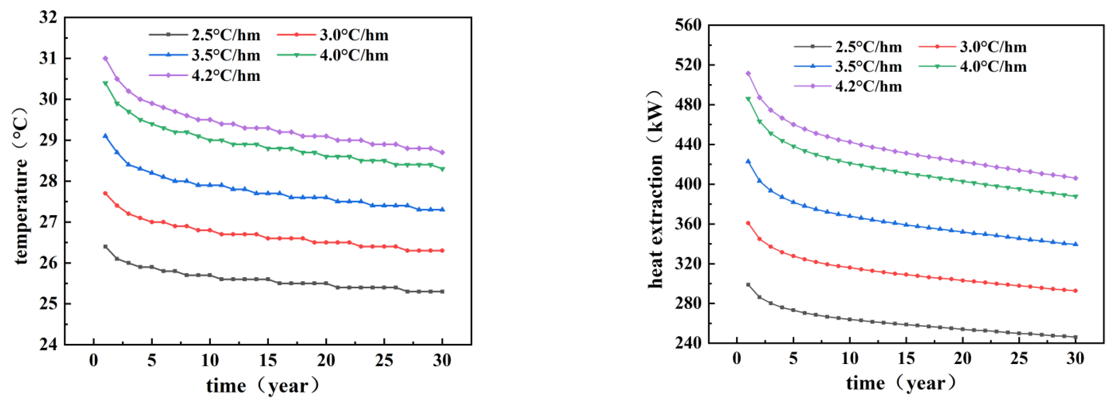
3/h, the rest of the simulation parameters were selected according to the previous selection. The simulation results curves of the flow production temperature and heat extraction for different geothermal gradients for the M1 and M2 wells are given in
Figure 5.
As can be seen from
Figure 5, the M1 well produced temperatures of 31.5, 33.2, 34.9, 36.6 and 37.4 °C in the first year of operation at geothermal gradients of 2.5, 3.0, 3.5, 4.0 and 4.2 °C/hm with heat extractions of 225, 285, 345, 405 and 431 kW, respectively. The production temperatures for continuous operation up to the 30th year were 30.3, 31.6, 32.9, 34.2 and 34.8 °C. The corresponding heat extractions were only 184, 230, 275, 321 and 341 kW, with extraction decreases of 18.2%, 19.3%, 20.3%, 20.7% and 20.9%, respectively.
It can be seen that in the early stage of geothermal well operation, the production flow temperature is high, and a substantial heat extraction can be obtained, but as the operation time continues, the production flow temperature gradually decreases, and the heat extraction also decreases. The main reason for this is that as the operation time continues, the heat of reservoir is continuously absorbed, and the reservoir temperature continues to decrease, so the production flow temperature and heat extraction also decrease. The lower geothermal gradient has relatively good stability under long-term operation, and the extraction drop is relatively small, but the flow-producing temperature and heat extraction are lower due to the lower reservoir temperature. The reason for this is that the reservoir temperature is low, and the temperature drop is relatively small. As the geothermal gradient increases, the heat extraction of geothermal wells rises very significantly, so places with large geothermal gradients are more suitable for single-well geothermal development.
The M2 well could reach 342, 429, 516, 603 and 642 kW of heat extraction in the first year of operation at the above five geothermal gradients. The corresponding heat extractions for continuous operation up to the 30th year were 277, 344, 410, 476 and 505 kW with heat extraction decreases of 19.0%, 19.8%, 20.5%, 21.1% and 21.3%, respectively. The increase in heat extraction was significant when the well depth increased. Compared to the M1 well, the heat extraction gains in the M2 well were 117, 144, 171, 198 and 211 kW at five geothermal gradients in the first year of operation and 93, 114, 135, 155 and 164 kW after 30 years of operation, respectively. By comparing the M1 and M2 wells, it can be found that the increase in well depth increased the flow path of the heat transfer fluid in the wellbore, resulting in a significant increase in the heat transfer area and therefore a significant increase in the produced flow temperature and heat extraction. However, the decrease in heat extraction under long-term operation was larger compared to the lower well depth, which may not be conducive to sustainability.
After this comparison, it can be found that an increase in well depth can make up for a low geothermal gradient, and the development of single-well geothermal systems in places with low geothermal gradients should appropriately increase the depth of the geothermal wells. Simultaneously, the higher the geothermal gradient, the greater the power gain obtained from the increase in well depth, but the long-term operational stability is relatively poor, and the heat extraction drop is large.
5.2. Influence of Injection Temperature
According to the geothermal gradient of 4.0 °C/hm and the injection flow rate of 30 m
3/h, the rest of the simulation parameters were selected according to the previous section. The simulation curves of the produced flow temperature and heat extraction for different injection temperatures for the M1 and M2 wells are shown in
Figure 6.
The M1 well produced water at 32.9, 36.6 and 40.3 °C and 450, 405 and 360 kW of heat in the first year of operation at injection temperatures of 20, 25 and 30 °C, respectively. After 30 years of continuous operation, the production temperatures were 30.2, 34.2 and 38.2 °C, and the heat extractions were 356, 321 and 286 kW with extraction decreases of 20.9%, 20.7% and 20.6%, respectively.
In the first year of operation, the M2 well produced water at 38.8, 42.3 and 45.8 °C and 657, 603 and 549 kW of heat at injection temperatures of 20, 25 and 30 °C, respectively. After 30 years of continuous operation, the production temperatures were 34.9, 38.7 and 42.5 °C, and the heat extractions were 518, 476 and 434 kW with extraction decreases of 21.2%, 21.1% and 20.9%, respectively.
These results show that as the injection temperature increased, the production flow temperature increased in both the M1 and M2 wells, showing a positive correlation, but the heat extraction then decreased, showing a negative correlation. The higher the temperature of the injected water, the more difficult it is to exchange heat with the reservoir, and it may not be able to fully absorb the heat, which is the main reason for this phenomenon. Higher injection temperatures not only play an important role in maintaining the stability of geothermal wells for long-term continuous operation (multiyear operating extraction reduction) but also allow for higher effluent temperatures, albeit at the expense of heat extraction. The lower the injection temperature, the higher the heat extraction and the more favorable for heating, but this does not mean that a single lower injection temperature is optimal. A low injection temperature also leads to a limited increase in the temperature of the water coming out, meaning that the process of extracting heat after the water is pumped out of the geothermal well becomes difficult, and the heat extraction process may be more costly.
5.3. Influence of Injection Flow
According to the geothermal gradient of 4.0 °C/hm and the injection temperature of 25 °C, the rest of the simulation parameters are selected according to the previous section. The simulation curves of the flow production temperature and heat extraction at different injection temperatures for the M1 and M2 wells are shown in
Figure 7.
In the first year of operation, the production temperatures of the M1 well were 40.7, 36.6 and 34.4 °C, and the heat extractions were 369, 405 and 439 kW at injection flow rates of 20, 30 and 40 m3/h, respectively. After 30 years of continuous operation, the production temperatures were 37.4, 34.2 and 32.5 °C, and the heat extractions were 291, 321 and 352 kW with extraction decreases of 21.1%, 20.7% and 19.8%, respectively.
In the first year of operation, the production temperatures of the M2 well were 48.6, 42.3 and 38.9 °C, and the heat extractions were 556, 603 and 649 kW at injection flow rates of 20, 30 and 40 m3/h, respectively. After 30 years of continuous operation, the output water temperatures were 43.7, 38.7 and 36.1 °C, and the heat production powers were 435, 476 and 516 kW with power decreases of 21.8%, 21.1% and 20.5%, respectively.
In summary, it can be found that the injection flow rate is negatively correlated with the temperature of the produced flow, and the higher the flow rate, the lower the temperature of the produced flow. The higher the injection flow rate, the more water that is exchanged with the reservoir for heat exchange per unit time, which also leads to a lower temperature of produced flow. However, there is a positive correlation with heat extraction, and the change in heat extraction is very obvious as the flow rate gradually increases. The high injection flow rate can improve the stability under continuous operation for many years, and the extraction variation under multiyear operation is relatively small. Although a larger injection flow rate will produce higher heat extraction, in actual engineering, the diameter of a single well is usually small, basically within 1 m, which cannot guarantee an injection flow rate that is too large. An excessive flow rate will also accelerate the decay of the flow production temperature with time, which is not conducive to the sustainable development and utilization of geothermal single wells.
5.4. Geothermal Energy Optimization
Summarizing the above multiple sets of simulation scenarios, patterns can be derived from three key factors:
(1) The geothermal gradient is positively correlated with the flow production temperature and heat extraction of the geothermal wells. The development of a single-well system is more effective in areas with high geothermal gradients, while areas with low geothermal gradients require deeper wells to increase their development value.
(2) The injection temperature is positively correlated with the flow production temperature of the geothermal well and negatively correlated with the heat extraction. Too high an injection temperature is not conducive for obtaining substantial heat extraction, while too low a temperature increases the difficulty of thermal extraction.
(3) The injected flow rate is positively correlated with the heat extraction of the single-well system and negatively correlated with the produced flow temperature. The higher the flow rate, the higher the heat extraction, but the injected flow rate should not be too high, otherwise it will make the temperature of the produced flow lower and the thermal extraction difficult.
Among the three influencing factors, the geothermal gradient has the greatest influence, followed by the injection temperature and the injection flow rate with the least influence. The geothermal gradient is limited by geothermal geological conditions and cannot be changed artificially. Thus, if we want to increase the heating area of a single geothermal well, we need to lower the injection temperature and increase the injection flow rate as much as possible. The above three laws were integrated, assuming that 100,000 m2 of heating was required; a single-well closed-loop geothermal system was selected for heating; and two kinds of wells, M1 and M2, are used as the starting points, combined with key factors, so as to propose the optimal layout of the single-well system for heating, in order to achieve the optimal working conditions.
5.5. Analysis of M1 Well Heating Potential
In this simulation, an injection temperature of 20 °C and an injection flow rate of 40 m
3/h were chosen. The simulation results under five geothermal gradients are shown in
Figure 8.
From
Figure 8, it can be found that when the geothermal gradient is 2.5 °C/hm, the heat extraction is 299 kW in the first year of operation and 246 kW after 30 years of operation. According to the national heating standard of 38 W/m
2, the heating area can be 7868 m
2 in the first year and 6474 m
2 after 30 years of continuous operation. When the geothermal gradient is 4.2 °C/hm, the heat extraction is 511 kW in the first year of operation and 406 kW after 30 years of operation, and the heating area is 13,447 m
2 in the first year and 10,684 W/m
2 after 30 years of continuous operation. The specific simulation results are shown in
Table 3.
From these simulation results, it can be found that the M1 well is relatively small in depth and cannot obtain a high flow production temperature and heat extraction in areas with a low geothermal gradient, which makes the development of the M1 well unsuitable. It is more valuable to develop the well in areas with a high geothermal gradient that is 1.7 times more the heating area at 4.2 °C/hm than at 2.5 °C/hm. Therefore, the M1 well is more suitable for areas with high geothermal gradients.
5.6. Analysis of M2 Well Heating Potential
The same injection temperature and flow rate as for the M1 well were used in this simulation. The simulation results under five geothermal gradients are shown in
Figure 9.
We found that when the geothermal gradient is 2.5 °C/hm, the heat extraction is 437 kW in the first year of operation and 357 kW after 30 years of operation. According to the national heating standard of 38 W/m
2, the heating area can be 7868 m
2 in the first year and 6474 m
2 after 30 years of continuous operation. When the geothermal gradient is 4.2 °C/hm, the heat extraction is 511 kW in the first year of operation and 406 kW after 30 years of operation, and the heating area is 13,447 m
2 in the first year and 10,684 m
2 after 30 years of continuous operation. The specific simulation results are shown in
Table 4.
The relatively large depth of the M2 well allows for a higher flow production temperature and heat extraction under the same conditions compared to the M1 well, but the increased depth of the well also makes the well more expensive to drill.
5.7. Design of Optimal Development Plan
A comprehensive analysis of the above two wells led to the following patterns:
(1) M1 wells are more suitable for development in areas with high geothermal gradients.
(2) M2 wells are more suitable for development in areas with low geothermal gradients.
(3) Lowering the injection temperature and increasing the injection flow rate as much as possible can obtain more heat extraction for heating.
If at least 100,000 m
2 of heating is required, the M1 or M2 well is selected for development for different geothermal gradients, and a simple static payback period estimate is made on this basis [
32].
Table 5 shows the design of the development schemes under different geothermal gradients.
It could be found that although the cost of drilling a single geothermal well is lower for the M1 well compared to the M2 well, the number of wells required to meet the heating demand of at least 100,000 m2 needs to be increased accordingly, so the total cost would be relatively higher, and the payback period would be relatively longer.
Although the payback period of the M2 well is short, the service life of geothermal wells may also be shortened due to long-term high-flow operation, so the change in geothermal field temperature before and after the extraction of geothermal wells is analyzed using a geothermal gradient of 4.2 °C/hm as an example (
Figure 10).
It could be found that after 30 years of continuous mining in the M1 well, the temperature of each temperature zone decreases more obviously and the radius of influence gradually increases with depth, but it can still barely maintain the original temperature of each temperature zone, and the development can still be continued under such mining intensity. However, after the M2 well was subjected to long-term continuous mining, the temperature change in the reservoir was very obvious, and the radius of influence was significant. The reservoir temperature in the near-well area decreased by more than one third, and it became very difficult to develop again under the original mining intensity. This is also the reason why heat extraction produces a significant decrease. This also reflects the fact that although the M2 well can obtain more heat extraction, it comes at the cost of reduced service life.
The results of the above analysis show that the M1 well is more suitable for areas with high geothermal gradients, and the M2 well is more suitable for areas with low geothermal gradients. Areas with high geothermal gradients can make up for the lack of well depth by their own higher reservoir temperature, while areas with low geothermal gradients can fill the lack of their own reservoir temperature by increasing the well depth. If the heating demand of 100,000 m2 is to be met, the input cost of the M1 well is relatively large and the payback period is long, but the temperature change in the reservoir is relatively small, and the service life of the geothermal well is longer, which is more suitable for sustainable development. The input cost of the M2 well is smaller, and the payback period is shorter, but the temperature change in the reservoir is significant, and it is relatively difficult to meet the needs of long-term development and utilization.
In addition, reasonable well spacing is also an important factor affecting the sustainable development of the single-well geothermal system. It can be inferred from
Figure 10 that the influence radius of temperature change under long-term continuous exploitation is large for both M1 and M2 wells. If the well spacing is too small (less than 50 m), the heat efficiency of multiple groups of single wells will be significantly reduced. Therefore, when developing multiple groups of single-well systems, the well spacing should be as large as possible. For example, the temperature influence radius of the M1 well is smaller than that of the M2 well, so the well spacing of the M1 well can be appropriately smaller than that of the M2 well, but it should not be too small. According to previous studies [
13], under such a scale of exploitation, the well spacing should be at least not less than 60 m. If conditions permit, the well spacing can be increased to more than 100 m. This measure is also more conducive to the long-term development and utilization of the single-well system.
6. Conclusions
To summarize the research in this study, the following conclusions can be obtained:
(1) The development of single-well systems is very dependent on geological conditions. When the ground temperature gradient is 2.5 °C/hm, the heat extraction of the M1 well is about 225 kW, and that of the M2 well is about 342 kW. When the ground temperature gradient reaches 4.2 °C/hm, it can reach 431 kW and 642 kW, respectively. The geothermal gradient is positively correlated with the flow production temperature and heat extraction of single-well systems, and the larger the geothermal gradient, the higher the corresponding flow production temperature and heat extraction.
(2) The injection temperature is positively correlated with the production flow temperature of the single-well system but negatively correlated with the heat extraction, while the injection flow rate is negatively correlated with the production flow temperature and positively correlated with the heat extraction. The effect of injection temperature on the heat extraction is more pronounced than that of the injection flow rate. Although lowering the injection temperature and increasing the injection flow rate can increase the heat extraction, it will lower the production flow temperature, and the low production flow temperature will increase the difficulty of heat extraction.
(3) Areas with high geothermal gradients are more suitable for the M1 well with smaller well depths due to higher reservoir temperatures, while extending the service life of single-well systems. However, if a single well-system is to be developed in areas with low geothermal gradients, a larger-depth M2 well is more appropriate due to the lower reservoir temperature. For example, when the geothermal gradient is higher than 3.5 °C/hm, it may be more appropriate to select the M1 well with a long service life.
(4) To meet the heating demand of 100,000 m2, the cost of developing M1 wells is relatively high, and the payback period is long, but a longer service life can be obtained. The cost of developing M2 wells is relatively low, and the payback investment period is short, but the useful life may be short. Taking the 4.2 °C/hm geothermal gradient as an example, the payback period of the M1 well is 4.4 years, and that of the M2 well is 3.9 years. However, the radial temperature response of the reservoir is more obvious. Therefore, the well spacing should be guaranteed to be at least 60 m when large-scale well cluster deployment is carried out.


