Abstract
With the increasing demand for heavy oil, core annular flow (CAF) is an economical method to transport heavy oil, and many researchers have explored the energy-saving aspects of the CAF method. This paper presents a review of CAF energy saving and factors affecting CAF energy saving. Among them, the energy saving of CAF mainly concerns the changes in pressure drop and drag reduction efficiency; the factors affecting the energy saving of CAF mainly concern the problem of stability, the issue of restarting the pipeline system, the impact of a nozzle, the impact of fouling on the flow in the pipe, and the problem of oil–water accumulation. The aim of this paper is to provide a reference for the practical application of CAF in heavy oil transportation.
1. Introduction
Petroleum is one of the primary sources of energy and materials in the world and is widely used in transportation [1], agriculture [2], pharmaceuticals [3,4], steel, and power industries. Due to the decreasing petroleum resources in the world, especially the depletion of light oil, many researchers have focused their research on the extraction of heavy oil, and many studies have focused on transportation after extraction [5]. Heavy oil has a high viscosity and poor flowability, and its transportation within the pipeline is difficult [6]. Heavy oil has a high drag when transported in the pipeline and requires a large pump power. To reduce the drag of heavy oil transportation, many researchers have used wall heating and dilution of heavy oil with solvents [7,8], but these methods are very expensive to use and only suitable for transporting heavy oil over short distances, and the economic efficiency and energy-saving efficiency are not satisfactory. Core annular flow (CAF) is an effective drag reduction method, the principle of which is shown in Figure 1. During heavy oil transportation, an outer ring of low-viscosity fluid (usually water) is used to wrap the inner core of heavy oil in order to avoid direct contact with the pipe and reduce the drag of transportation.
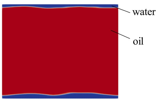
Figure 1.
Principle of CAF [9]. (Red for oil and blue for water.)
Oil companies have a long history of research on CAF. Isaacs and Speed first discussed water lubrication of light oil in 1904 when they envisioned the stabilization of light oil by centripetal acceleration generated by rifling the pipe [10]. Clifton and Handley of Shell Development proposed a method to prevent pump oil emulsification by removing water before pumping and re-injecting water into the pipeline after pumping [11]. A 55 km long pipeline was used to study the CAF technology for transporting high-viscosity oil (1.5 Pa·s) in Venezuela [12]. A fuel, Orimemulsion, produced in Venezuela and marketed by Bitor, was also transported using the CAF method [13]. The heavy oil industrial pipeline built by Shell Development in California is 38 km long and 15 cm in diameter. For many years, it produced viscous crude oil at a flow rate of 24,000 barrels per day in a water-lubricated condition [14].
The CAF method has better drag reduction than any other techniques [15]. Many researchers have studied the variation in pressure drop and drag reduction efficiency in CAF, stability problems, restarting of the pipeline system, the effect of nozzles, and the effect of fouling in the pipeline on the flow using experimental and numerical simulations. This paper provides a review of CAF energy saving and the factors affecting CAF energy saving, to provide a reference for the practical application of CAF in industry.
2. Pressure Drop and Drag Reduction Efficiency
Brauner proposed a criterion for the existence of stable CAF. The criterion shows that CAF can occur in a pipe when there is a large difference in the viscosity of the two fluids, but not a large difference in density [16].
2.1. Horizontal Pipe
One of the earliest CAF studies dates back to 1949, when Clark and Shapiro proposed a patent for transporting viscous oil by injecting oil and demulsifying agents into crude oil pipe. The viscosity of the oil was 0.8–1 Pa·s. Their report shows that injecting 24% water into the pipe could reduce the pressure gradient by 7.8–10.5 times; the best pressure reduction was achieved when 8–10% water was injected [15].
Bannwart studied CAF in horizontal and vertical pipes. The research shows that interfacial tension prevents the core layer from splitting into smaller pieces, but its importance decreases in larger pipes. The pressure drop of CAF is similar to that when only water is present in the pipe [16].
Bensakhria et al., optimized the parameters affecting the CAF process using an experimental method, which was conducted under a steady laminar flow at a moderate flow rate. The viscosity of the oil was 5 Pa·s. The research shows that compared with the same product without lubrication by the CAF method, the injection of water in the annular layer in the pipe wall leads to a pressure drop reduction of more than 90%. A comparison of the pressure drop with and without lubrication is shown in Figure 2. The pressure drop decreases as the flow rate increases and the density difference of the fluid in the pipe is the particular reason for the variation in the pressure drop with the flow rate [17].
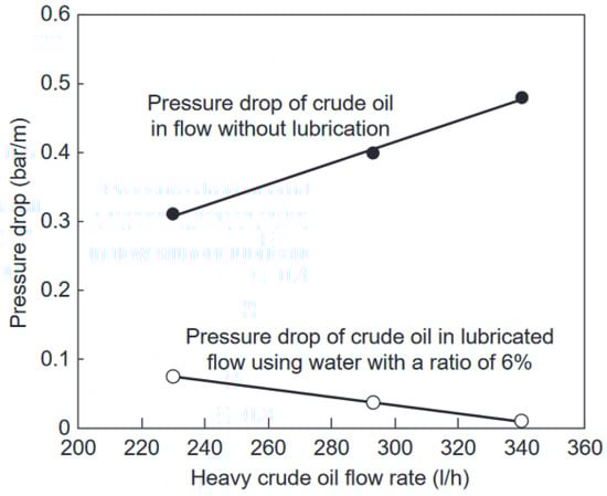
Figure 2.
Comparison of pressure drop with and without lubrication [17].
Asiegubu and Asakura measured the pressure loss of CAF in three horizontal pipes with inner diameters of 25, 52.7, and 80.1 mm, using high-viscosity oil as the core layer and water as the annular layer. Oils with viscosities of 2.82 and 8.92 Pa·s at 20° were selected. The research shows that the pressure loss is weakly correlated with oil viscosity and oil–water flow ratio [18].
Rodriguez et al., collected the data on pressure gradients of oil and oil–water flow by experimental methods in a steel pipeline. The length of the pipe was 274 m and the diameter was 7.7 cm. The viscosity of the oil was 36,950 mPa·s. To quantify the gain for transporting high-viscosity oil, the concept of the frictional pressure gradient reduction factor was presented in the paper. The research shows that CAF increases the oil flow rate by 7 times and reduces the pressure loss by 4 times, with a gain of about 150 times [19].
Andrade et al., used ANSYS CFX to model and numerically simulate the oil–water flow in a horizontal pipe and a T-junction. The viscosity of the oil was 10 Pa·s. In the paper, the pressure and volume fraction distributions of CAF in the horizontal pipe and T-junction were analyzed. The research shows that in the horizontal pipe, the pressure drop value is 5220 Pa in the CAF mode. In the T-junction, the pressure drop value is 7324 Pa, which is higher than that in the horizontal pipe, due to the inefficient transport of heavy oil in contact with the pipe wall during the flow and the change in the flow mode from CAF to stratified flow [20].
Tripathi et al., conducted a numerical simulation of CAF in a horizontal pipe using ANSYS FLUENT. The annular layer of CAF was water and the core layer was high-viscosity oil. The research shows that the lower the interfacial tension, the more stable the CAF. When the interfacial tension is low, the pressure drop is also low, which is similar to that when the pipe is a single-phase water flow. This shows that CAF is an economically viable method [21].
Desamala et al., used ANSYS FLUENT to simulate the flow of moderate-viscosity oil–water CAF in a horizontal pipe. The oil–water viscosity ratio was 107. The research shows that the total pressure of the oil–water mixed fluid decreases with increasing oil velocity in the CAF. The volume fraction of oil has a maximum value at the center of the CAF, while in the stratified flow, the maximum value occurs at the upper side of the pipe [22]. Desamala et al., conducted similar numerical simulations subsequently and analyzed in detail the flow pattern and the predictions of the radial distribution of volume fraction, pressure, and velocity [23].
Jing et al., analyzed the variation in stability and pressure drop of CAF by experimental and numerical simulation methods. The range of oil viscosity was 1143.3–55,306.4 Pa·s. The research shows that only the density difference affects the formation of eccentric CAF. Proper adjustment of the viscosity difference helps maintain a stable CAF, and the pressure drop decreases slightly as the viscosity of the heavy oil decreases. The velocity has the greatest impact on the eccentricity degree of the CAF. Properly increasing interfacial tension helps maintain CAF stability [24].
Lu et al., combined TRIZ and extenics methods to design a device containing a spiral pipeline for maintaining the stability of the transport process of heavy oil. The viscosity of the oil was 0.22 Pa·s. In the paper, a scheme for maintaining stability was designed based on the principle of divergence analysis of a characteristic multi-value. The designed scheme was optimized according to the goodness evaluation method and numerical simulation. The VOF model and CSF model were used to numerically study the phase, pressure, and velocity distributions. The development of CAF is shown in Figure 3 [25].

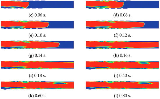
Figure 3.
Development of CAF [25]. (Red for oil and blue for water.)
2.2. Vertical Pipe
Parda and Bannwart conducted CAF upward flow experiments in a 1-inch vertical pipe. The viscosity of the oil was 17.6 Pa·s. A theoretical approach to obtain the pressure loss in the pipe is presented in the paper. The research shows that the frictional pressure drop of CAF is 700–2000 times lower and the total pressure drop is 45–150 times lower than those of a single-phase oil flow. The friction pressure drop is the total pressure drop minus the gravity term of the mixture. The energy savings of CAF are more significant when the two pressure drops are lower. The optimal water–oil input ratio is in the range of 0.07–0.5, depending on the superficial velocity of the oil [26].
Ghosh et al., conducted a computational fluid dynamics (CFD) study to simulate the downward flow of CAF in a vertical pipe. The viscosity of the oil was 0.2 Pa·s. The research shows that the friction pressure gradient increases with the superficial velocity of oil and water; however, the increase in the friction gradient is greater. It is also shown that, as the water velocity increases, the core layer becomes a thin, wavy core layer. Wall shear increases with increasing water and oil velocities and changes dramatically when a certain oil velocity is exceeded [27].
Bannwart et al., conducted an experimental study in a 300 m deep oil well. The viscosity of the oil was 2000 mPa·s. Compared to the case without lubrication, it was found that the bottom hole pressure is reduced by 25% when oil–water CAF is created, which indicates a significant reduction in frictional pressure drop. At a water volume fraction of about 5%, it is possible for the oil flow in the CAF to reach 2.5 times the maximum oil flow in a single phase [28].
Cavicchio et al., conducted CAF experiments in a vertical pipe. The range of oil viscosity was 557–1729 cP. The slip ratio and holdup were measured in the experiments. The measured friction pressure gradient of CAF is the same or even lower than that of pure water flow. Compared to pure oil flow, a frictional reduction factor as high as 100 times and a total reduction factor as high as 4 times were observed for the maximum oil viscosity studied (1729 cP). The reduction factor increases with the increase in the thickness of the annulus layer, and increases exponentially with the increase in the oil viscosity [29].
2.3. Other Structural Types of Pipes
Brauner evaluated the potential of CAF configurations in reducing pressure loss for the issue of scaled-up pipe sizes. The paper presents a model for predicting pressure drop, etc., and the function of pressure drop and drag was derived. The core layer of the CAF was laminar and the annular layer was laminar or turbulent. The research shows that the pressure drop of CAF is similar to that of a lower-viscosity fluid flowing alone in a pipe. When the annular layer is turbulent, the correlation between the pressure drop ratio and the pipe diameter is weak [30].
Balakhrisna et al., studied the flow pattern changes and pressure profiles of high-viscosity oil–water passing through a sudden-constriction and sudden-expansion horizontal pipe and compared them with the low-viscosity oil–water flow. The viscosity of the high- and low-viscosity oil is 0.2 and 0.0012 Pa·s, respectively. The CAF in the sudden contraction pipe and sudden expansion pipe is shown in Figure 4a–e. The research shows that there is no correlation between the change in pressure profile and the viscosity of the fluid, and no correlation between the loss coefficient and the flow pattern [31].
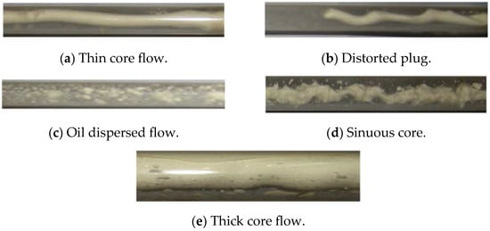
Figure 4.
CAF in a sudden-contraction pipe and sudden-expansion pipe [31].
Sharma et al., studied experimentally the geometry of the bend and the flow direction through the bend on the flow of low- and high-viscosity oil–water CAF. In this case, the geometry of the bend was U-shaped and rectangular, and the CAF flowed upward, downward, and horizontally. The viscosity of the high- and low-viscosity oil was 0.22 and 0.0012 Pa·s, respectively. The research shows that the pressure drop is higher for rectangular bends compared to U-shaped bends. In the low-viscosity oil–water CAF, the loss coefficients for each flow case are independent of the flow pattern; the research also proposed two different pressure drop correlations for each bend geometry to estimate the liquid–liquid pressure drop across the bend [32,33].
Jiang et al., numerically simulated the CAF through a U-shaped bend by CFD based on the Eulerian model, and discussed the effects of flow parameters and annular layer thickness on the CAF. The paper also compared the results of the Eulerian model and the volume of fluid method (VOF) model. The initial viscosity of the oil was 0.22 Pa·s. The research shows that higher oil density leads to an increase in the total pressure gradient. In the turbulence model, the total pressure gradient first decreases to a minimum value and then increases as the viscosity of the oil increases. The total pressure gradient gradually decreases as the interfacial tension coefficient increases. The annular layer thickness affects the total pressure gradient, as shown in Figure 5, where the pressure drop decreases and then increases as the thickness increases. The pressure drop is lower when the thickness is in the range of 1.25–1.75 mm [34].
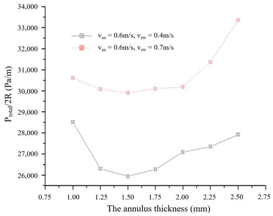
Figure 5.
Relationship between annular layer thickness and pressure drop [34]. ( and are the superficial velocities of water and oil, respectively.)
Jiang et al., used a VOF model and a continuous-surface-stress (CSS) model to numerically simulate CAF through a rectangular bend, as shown in Figure 6. The viscosity of the oil was 0.22 Pa·s. The research shows that for pressure gradient and wall shear stress, its variation is more correlated with oil density, fluid consistency coefficient, and flow behavior index; the flow direction has little impact on it; it has a maximum value when the CAF flows upward. When the aspect ratio L/D (L is the distance between the axes of the two straight pipe sections in a ∏-bend, and D is the pipe diameter) of the bend is 14–21, the oil–water inlet diameter ratio is 0.667–0.75, and the corner radius ratio (the ratio of the radius of the corner elbow to the pipe diameter) is greater than 2.5, a more stable CAF may occur in the ∏-shaped bend [35].
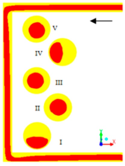
Figure 6.
Rectangular bend [35]. (Red for oil and yellow for water.)
Dehkordi et al., studied the high-viscosity oil–water CAF passing through three pipe diameter configurations of sudden expansion pipes. The viscosity of the oil was 0.838 Pa·s. Numerical simulations were conducted in the paper using ANSYS FLUENT and experimental validation was carried out. Characteristics of the two-phase flow, such as pressure gradient, phase space distribution, and flow regime, were extracted. The research shows that when the oil in the core layer is far from the singularity (location of sharp-edged area change), the sudden expansion pipe will make its eccentricity degree and thickness greater [36].
Coelho et al., studied the CAF flow in a 180° bend by an experimental method. The viscosity of the oil was 2750 mPa·s. The experiments show that the maximum power reduction factor obtained using the CAF method is 2.2, which implies a saving of half the cost of transporting the same volume of oil [37].
Garmroodi and Ahmadpour conducted a numerical simulation of the flow of a high-viscosity oil–water CAF in a gradually expanding inclined pipe. The gradually expanding inclined pipe is shown in Figure 7. The development of CAF is shown in Figure 8. The research shows that for the overall pressure drop, the wax content of 2.3% and 5.5% reduces it by 22% and 80%, respectively; when the expansion angle of the CAF domain is increased from 3.7° to 45°, it increases more than 4 times; when the inclination angle is increased in the downward flow, it has a tendency of monotonic decrease; in the upward flow, it has a local maximum near the inclination angle of 45°; its variation with the inclination angle is 38% in the upward flow and 32% in the downward flow [38].
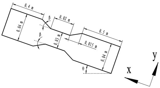
Figure 7.
The gradually expanding inclined pipe [38]. ( is the expansion angle, is the inclination angle.)
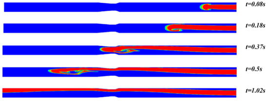
Figure 8.
Development of CAF [38]. (Red for oil and blue for water. The expansion angle and inclination angle are 3.7° and 0°, respectively.)
Jing et al., conducted an experimental study of CAF flow in a horizontal pipe containing a 90° elbow. The viscosity of the oil was 1055.3 mPa·s. The variation in flow patterns and frictional pressure gradients were discussed in the experiment to assess the effect of the elbow on the stability of CAF development. The research shows that the elbow has a negative impact on the downstream, which will make the friction pressure gradient increase and the reduction factor and the transfer efficiency of oil decrease. To ensure a high transfer efficiency, the water input component should preferably be controlled at a critical threshold, while the oil flow rate should be increased to the limit [39].
Dianita et al., applied CFD methods to numerically simulate CAF through pipes of two shape configurations. The pipes were configured with T- and Y-shaped junction pipes. The viscosity of the oil was 0.838 Pa·s. The research shows that for the average value of the pressure gradient and the standard deviation of the pressure drop, the pipe diameter of both the inlet and the outlet has an effect on it, while the connection angle has no effect on it. The design of T- and Y-shaped connection pipes is ideal when the connection angle and outlet diameter are large, and the inlet diameter is small [40].
Jiang et al., studied the interfacial fluctuations of CAF. The viscosity of the oil was 0.697 Pa·s. The research shows that in a straight pipe, the head loss increases when the average velocity increases. In a sudden contraction pipe, due to the change in the flow cross-section, interfacial fluctuations occur in the pipe, reducing energy saving. In a bend, the change in flow direction creates centrifugal forces, which cause large interfacial fluctuations in the pipe and also result in reducing energy saving. The research also shows that changes in pipe cross-section and flow direction should be minimized to maintain good energy saving. Decreasing interfacial tension also contributes to energy saving. Interfacial fluctuations are mainly suppressed by adjusting flow parameters and adding surfactants [9].
3. Stability
As shown in Figure 9, when the CAF changes from a steady to an unsteady state, the oil sticks to the wall, which, in turn, reduces the energy saving effect. CAF maintains long-term stability to show the advantages of CAF oil delivery. Therefore, it is necessary to study the factors affecting the stability of CAF.
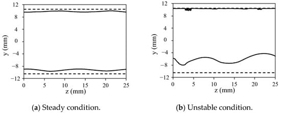
Figure 9.
The transition of CAF state [41]. (The dashed line is the wall; the solid line is the interface.)
Ooms et al., studied the flow of CAF in a horizontal pipe. The viscosity of the oil was 3300 cP. The paper concerned the equilibrium of buoyancy in the core layer. As shown in Figure 10, the core of the flow model is a solid center whose outer layer is a high-viscosity liquid. The development of interfacial waves was calculated using hydrodynamic lubrication theory. The research shows that the interfacial waves produce pressure changes and generate a net force on the oil core. When the pressure gradient over the pipe is large enough, an equilibrium is formed between the buoyancy force and the hydrodynamic force over the core layer, resulting in an eccentric CAF. As the pressure gradient decreases or the buoyancy force increases, the eccentricity of the core layer increases [42].
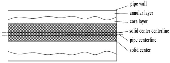
Figure 10.
Flow model [42].
Selvam et al., studied the linear stability of variable viscosity, and miscible CAF. The research shows that the flow is stable at any Reynolds number when the viscosity ratio is less than a critical value. When the viscosity ratio is greater than the critical value, the flow may be unstable even when there is a more viscous fluid in the core layer. For core layers with low viscosity, the corkscrew mode is inviscidly unstable, while for the axisymmetric mode, it is unstable at a small Reynolds number and a high Schmidt number. In the normal mode analysis, the perturbations are assumed to be periodic in the azimuthal direction and β denotes its real wavenumber. The β values for the corkscrew and axisymmetric modes are 1 and 0, respectively. Increasing the interface thickness makes the CAF more stable. The flow is most unstable when the interface between the two fluids is located at about 0.6 times the pipe radius. There is no sudden change in the stability of the radial direction of the interface. The instability mainly originates from the less viscous fluid near the interface [43].
Bassom et al., studied the stability of CAF when the interface of CAF was covered by immiscible surfactants. The concentric CAF fluid layer was around a solid circular rod. The research shows that with proper setting of the basic flow shear rate at the interface, the CAF can flow stably under zero Reynolds number (in this reference, zero Reynolds number is set in the stability analysis, which is not the actual flow state of zero Reynolds number). If the viscosity of the inner fluid is greater than that of the outer fluid, the CAF can flow stably when the inner layer is thin, but not when the outer layer is thin. If the annular layer is thin enough, a conventional rodless CAF can be stable under zero Reynolds number [44].
Ooms et al., studied how to balance the buoyancy forces acting on the core layer in CAF caused by the density difference between the core layer and the annular layer. The viscosity of the oil was 0.601 kg/ms. The research shows that the buoyancy force drives the core layer to start rising, and then it equilibrates with the forces generated by the motion of the waves at the CAF interface. Finally, the core layer reaches the eccentric equilibrium position. When the annular layer flows at high Reynolds number, the levitation of the core layer is caused by inertial forces. This is because in the calculation without the inertia term, the core layer rises until it touches the pipe wall. At low Reynolds numbers, the CAF becomes eccentric and stable in both calculations with and without the inertia term. When there is no inertia term, the viscous (lubricating) force generates pressure to counteract the upward buoyancy force [45].
Chattopadhyay et al., discussed the temporal instability of viscosity stratified miscible CAF in a slippery pipe. The physical mechanism of instability occurring in the double-diffusive (DD) system is explained in the paper by energy budget analysis. The research shows that slip has the dual effect of stabilizing or destabilizing the flow. The study can be extended to consider the unmodular stability analysis of CAF, which makes it possible to quantify wall slip effects [46].
Sahu studied the linear instability properties of CAF consisting of Newtonian fluid and Bingham fluid. The paper focuses on the effect of yield stress on the stability of the annular layer. The linear stability analysis shows that the corkscrew mode is more unstable than the corresponding axisymmetric mode. The stability of the flow seems to be destabilized by the Bingham number by changing the velocity configuration. The energy generated by the viscosity disturbance gradient in the radial direction and the energy transfer from the basic flow to the disturbance through the “Reynolds stress” term are responsible for the instability. The critical Reynolds number for the corkscrew mode also decreases with increasing Bingham number, indicating that the yield stress affects the instability [47].
4. Pipeline System Restart
Peysson experimentally studied the flow, stopping, and restarting of viscous heavy oil. In this case, the heavy oil used water or brine as a lubricant. The viscosity of the oil was 4.75 Pa·s. The research shows that by adding salt to the water phase, the system can stop the flow for a certain time and restart without a large pressure. In the paper, different salts were also tested, and the function between the amount of salt and restart pressure was studied [48].
Strazza and Poesio restarted a CAF pipeline system with oil–water as a stratified state. The viscosity of the oil was 0.9 Pa·s. The paper focused on the cleaning of the pipe with water and studied the maximum pressure drop and the time consumed to clear the fouling in the first phase of the restart. The pressure drop and time were used as a function of the standstill period, initial oil hold-up, and cleaning speed. The research shows that the standstill period and the initial oil hold-up directly determine the initial maximum of the pressure drop. It is possible to lower the pressure drop by gradually increasing the speed of the cleaned water [49].
Alagbe conducted a numerical study of the shutdown and restart of the CAF in a horizontal pipe. The viscosity of the oil was 3.3 and 10 Pa·s. The restart surges were explored in the paper to help in pump specification design and selection. The research shows that compared to the respective surges of oil and water, the surges of CAF are both higher than them after the restart. Surges increase when the oil viscosity decreases [50].
Andrade et al., conducted a numerical study of the physical characteristics of CAF using ANSYS CFX. The viscosity of the oil was 10 Pa·s. The research shows that the annular flow pattern disappears after the pump is turned off, which leads to a rapid increase in pressure drop. The pressure drop in the system continues to increase during 12 s when the water pump is turned off until it reaches a value of 71,240 Pa. When the water pump starts again, the pressure drop appears to oscillate rapidly, peaking at 87,421 Pa, and then begins to return to the annular flow mode. In the annular flow mode, the system pressure drop decreases and remains almost constant after 20 s. After turning off and restarting the pump, the pressure drop remains almost constant at 2826 Pa, which is close to the pressure drop at the beginning of the simulation (2727 Pa at 1 s) [51].
Livinus et al., conducted experiments on the shutdown and restart of a high-viscosity oil transport system in a PVC horizontal pipe of 5.5 m length and 26 mm inner diameter. The results were used to establish correlations for predicting the restart process of CAF. The range of the oil viscosity was 1.9–3.883 kg/ms. In the paper, the correlation was tested for its predictive capability based on measured restart times and pressure drop changes, and slightly higher but still reasonable predictions were obtained [52].
Jiang et al., combined VOF and continuous surface force (CSF) models to simulate the CAF flowing through a valve and analyzed the effect of the open rate of a valve on the vortex and oil distribution characteristics. The viscosity of the oil was 0.22 Pa·s. The research shows that there are many vortices inside and behind the valve. As shown in Figure 11, as the open rate increases, the aggregation rate increases. As the flow rate increases, the rate of change of the vortex position is larger, and the oil aggregation rate decreases. High-viscosity oil has a larger aggregation rate after flowing through the valve, and the change in the vortex core position is relatively slow. When the vortex passes through the oil in the core layer, the oil will be dispersed and cause the CAF to become unstable. The numerical simulations in the paper can provide insight into much information about the oil–water CAF in the ball valve, such as the development of the flow, the distribution of the two phases, the distribution of the pressure, the turbulent kinetic energy, and the distribution of the velocity [53].
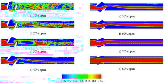
Figure 11.
Comparison of different open rates of the valve [53]. (Red for oil and blue for water.)
5. Nozzle
In the process of transporting viscous oil with water lubrication, both phases (water and oil) are introduced into the oil–water mixing pipe by the nozzle, which, in turn, creates a CAF structure in the oil–water mixing pipe.
Sotgia et al., conducted a set of experiments by varying the shape of the oil–water mixing pipe to determine the dependence of the flow pattern and pressure drop on the CAF inflow method. The dimensions of the original two-phase mixing pipe are shown in Figure 12. The different shapes of the two-phase mixing pipes are shown in Figure 13. The research shows that the change in the shape of the mixing pipe affects the change in pressure drop. In terms of the reduction factor, the reduction factor of the pipe with a progressive shoulder is larger than that of a non-progressive shoulder [54].
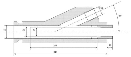
Figure 12.
The dimensions of the original two-phase mixing pipe [54].
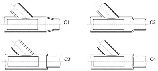
Figure 13.
Two-phase mixing pipes with different shapes [54].
Macías-Hernández et al., studied the effect of nozzles on forming CAF in horizontal pipes by CFD. In the paper, the flow of fluid in the core layer from the nozzle and the process of the two-phase fluid junction were studied, and the relationship between the nozzle and the interface formation was analyzed. The research shows that at the nozzle outlet, the reverse flow of water caused a slight contraction of the core layer. The role of the nozzle becomes vital because of the interfacial shear and entrainment caused by the eccentricity of the core layer to form the interfacial delamination [55].
Jiang’s research group has conducted a lot of research in the field of the effects of nozzles on CAF stabilization, designed several nozzles for stabilizing CAF flow, and filed several patents [56,57,58,59].
An annular flow nozzle was designed to act as a pressure reducer for the CAF. The nozzle structure is shown in Figure 14. A buffer section is set on the oil inlet pipe, and the inner diameter of the buffer section is from small to large to disperse the pressure of the heavy oil in the oil inlet section on the heavy oil in the buffer section, so that the flow of heavy oil tends to be stable. As the outer diameter of the buffer section changes from small to large, when the water flows into the flow gap area where the buffer section is located, the transport space of the water gradually becomes smaller, reducing the flow velocity of the water and reducing the pressure on the water flow in the flow gap area corresponding to the oil outlet section, so that it flows steadily. Both tend to have a stable state, improving the stability of the CAF [56].
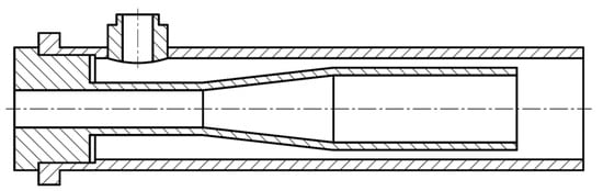
Figure 14.
Nozzle structure [56].
The external and internal structures of a cast annular flow generator are shown in Figure 15. The designed annular flow generator is used to solve some disadvantages of some existing nozzles: the oil inlet pipe is overhanging set inside the outer pipe; when the heavy oil is pumped into the oil–water mixing device, the heavy oil will cause a certain impact on the pipe, and this impact directly affects the stability of the CAF flow pattern. In addition, the operation of the general annular flow generator requires the use of two separate devices to transport heavy oil and water into the pipe, which increases the economic cost of this transport mode, and the inflow of water can cause some impact on the inlet pipe [57].
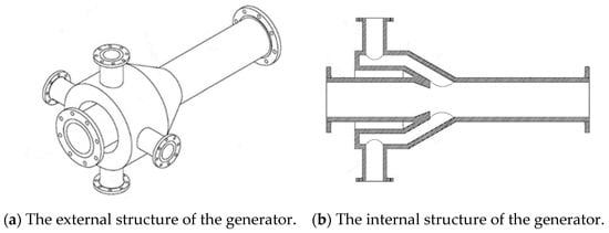
Figure 15.
The structure of the generator [57].
A pulsating wave annular flow generator was designed to maintain the stability of an unstable CAF in a pipe, thereby improving the efficiency of heavy oil transportation. The internal structure of the pulsating wave annular flow generator is shown in Figure 16. The pushing mechanism inside the generator pushes the oil pipe to make a reciprocating motion in its radial direction, which causes a periodic fluctuation in the oil pipe in the opposite direction of the destabilization of the oil phase, thus making the destabilized CAF stable again [58].
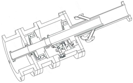
Figure 16.
The internal structure of the pulsating wave annular flow generator [58].
A wedge wave annular flow generator was designed with reference to the principle of fluid dynamic pressure lubricant film. During the water phase operation, the CAF that is about to be destabilized is kept stable by controlling the water flow to strike the pressure plate to generate a wedge wave annular flow, which produces pressure in the opposite direction of the buoyancy force caused by the density difference, thus increasing the stable transport distance of heavy oil and improving the transport efficiency of heavy oil. The wedge wave generator and the CAF generated by it are shown in Figure 17 and Figure 18, respectively [59].
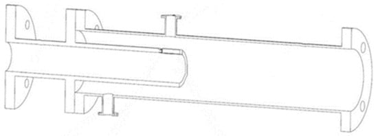
Figure 17.
The wedge wave generator [59].
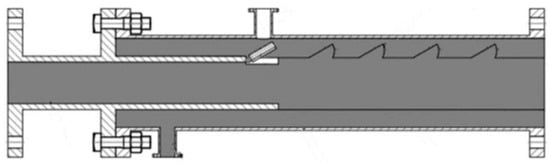
Figure 18.
The CAF generated by the wedge wave generator [59].
6. Fouling
Initially, the fouling adheres irregularly to the pipe wall, and as it gradually accumulates, oil layers are formed. These oil layers may significantly reduce the useful cross-sectional area of the pipe and the oil volume in the pipe, substantially increasing the pressure drop [13].
Da Silva et al., studied a surface modification method to reduce or eliminate the heavy oil adhering to the inner wall of the pipe in the CAF transport method. Oxidation of the surface and changes in wall roughness were conducted, and the effects of these changes were quantified. The paper describes the changes in the wetting behavior of the pipe wall by measuring the contact angle of the oil/water/surface system. The surfaces studied included PVC, stainless steel, enameled steel, galvanized steel, and commercial steel. The effects of salt, pH, and temperature on wetting behavior were also studied in the paper. The research shows that enameled steel, stainless steel with a roughness of 2.5 μm, oxidized polymers, or oxidized commercial steel can make heavy oil transport more efficient. Water with a pH outside the range of 4–8 results in a lower contact angle, making heavy oil transport more efficient. In addition, the addition of sodium meta-silicate helps to avoid fouling [60].
Grassi et al., studied the oil–water flow in pipes with various inclinations. The inclination angles of the pipes were 0°, +10°, −10°, and +15°. The oil–water viscosity ratio was 800. From the experimental analysis, there is no significant difference between the pipeline systems with different inclinations, which may be related to the Eötvös number of the system itself. Fouling only occurs at low oil and water flow rates [61].
Balakhrisna et al., studied the changes in fouling during the process of CAF through a sudden-constriction pipe and sudden-expansion pipe. The research shows that the high-viscosity oil can establish a stable CAF after sudden expansion in a horizontal pipe, but it tends to make the fouling pollute the pipe wall; the sudden contraction of the high-viscosity oil reduces the thickness of the oil core, which decreases the chance of creating fouling [31].
Ghosh et al., conducted a CFD analysis of CAF through a return bend pipe. The viscosity of the oil was 0.22 Pa·s. In the paper, the CAF was mainly considered for upward flow in a U-shaped bend. However, to compare the fouling characteristics, downward flow and horizontal flow cases were also considered. A comparison of the experimental and numerical simulations of oil fouling to the wall in a U-shaped bend is shown in Figure 19. The research shows that as the radius of curvature of the U-shaped bend increases, the advantage of CAF is weakened, and the pressure drop in the pipe is similar to that without the CAF method. Compared with the downward and horizontal flow, CAF has less chance to produce fouling when flowing upward in a U-shaped bend. When the radius of curvature of the U-bend exceeds a certain value, the fouling at the bend increases sharply [62].
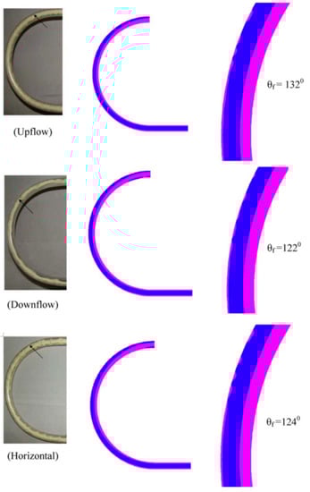
Figure 19.
Oil fouling to the wall in the U-shaped bend [62]. ( is an angle describing the initial point of the fouling. Blue for oil and magenta for water.)
Kaushik et al., studied CAF through a sudden contraction and expansion of pipes. Numerical simulations of the lubricant–water CAF using the VOF model were conducted in the paper, and the simulated data and experimental results are well matched. The viscosity of the oil was 0.22 Pa·s. The paper analyzed the fouling characteristics of the lubricant during the sudden expansion of the pipe. The research shows that increasing the water inflow or pipe diameter helps to reduce fouling [63].
Jiang et al., studied CAF in a U-shaped bend using the VOF model and Eulerian model. The research shows that the wall shear stress of oil at the upper wall surface gradually increases from the midstream of the pipe. The wall shear stress of water is greater at the outer side of the midstream and the lower wall surface located downstream of the U-bend. The two-phase distribution is shown in Figure 20. This phenomenon indicates that with the development of CAF, under centrifugal force, CAF will produce fouling, polluting the wall surface downstream of the pipe [34].
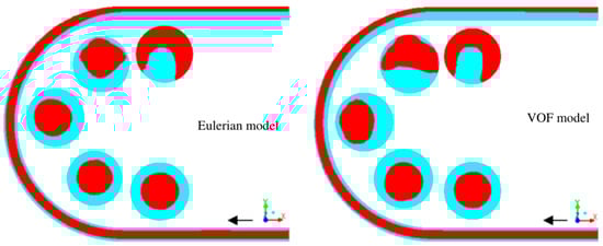
Figure 20.
Two-phase distribution [34]. (Dark color for oil and light color for water.)
Jiang et al., simulated the CAF flow through a ∏-shaped bend. The viscosity of the oil was 0.22 Pa·s. The research shows that increasing the volume fraction of input water, flowing upward in the bend, and using a high-viscosity oil will reduce the chances of producing fouling. The fouling in the pipe is shown in Figure 21. Suitable geometric parameters for a ∏-bend are L/D < 18.75, D1/D about 0.71, R/D = 2–2.5, and e < 0.01 mm, where L is the distance between the axes of the two straight sections in the ∏-bend, D is the pipe diameter, D1 is the oil inlet diameter, R is the radius of the bend’s fillet, and e is the wall roughness [64].
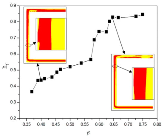
Figure 21.
The fouling in the pipe [64]. ( represents the ratio of the height of the fouling point to the total height of the bend, represents the volume fraction of the input water. Red for oil and yellow for water.)
Ooms et al., studied the possibility of eccentric CAF and the deformation of the CAF interface. The research shows that a stable eccentric CAF is possible and the direction of the eccentric position depends on the normal stresses at the core–circular interface. When these normal stresses differ too much from those in a concentric and circular CAF, the walls produce fouling [65].
Jiang et al., conducted numerical simulations of the CAF flow through an elbow using the VOF model and the CSF model. The viscosity of the oil was 0.2 Pa·s. The research shows that when the oil density and fluid consistency coefficient increase or the flow behavior index decreases, the pressure gradient, the fouling angle, and the wall shear stress increase. The diameter of the bend used in this paper is small, and the flow direction has less impact on the total pressure gradient and fouling angle. When the curvature ratio 2R/D of the bend or the inlet diameter ratio D1/D is higher than a certain value, the total pressure gradient increases and the fouling angle decreases significantly, where R is the radius of curvature of the bend, D is the pipe diameter, and D1 is the oil inlet diameter. The curvature ratio of the bend should be in the range of 16–20 and the inlet diameter ratio should be in the range of 0.67–0.75 to form a more stable CAF when oil–water passes through the bend [66].
Jiang et al., studied the CAF in a U-shaped bend. The effects of inclination angle, inlet diameter ratio, oil properties, and pipe material on fluid dynamics and fouling characteristics were studied in the paper. The viscosity of the oil was 0.22 Pa·s. The research shows that a larger fouling surface results in a higher equivalent two-phase loss coefficient (). When the viscosity of oil in the CAF is higher, the chances of producing fouling are reduced. As the inclination angle of the U-bend increases, the area-weighted average of oil volume fraction () increases, and and the angle of the bend at the fouling point () decrease. Therefore, it is reasonable for CAF to flow upward through a U-shaped bend with a small inclination angle. When the oil–water inlet diameter ratio increases and the water inlet area decreases, , , and will decrease. When the oil–water inlet diameter ratio is 0.6–0.75, the CAF through the U-shaped bend is more stable. In addition, pipe materials with hydrophilic properties can reduce fouling [67].
Coelho et al., studied CAF in a horizontal–vertical–horizontal pipe. The research shows that irregularities in the pipeline route tend to lead to fouling, that irregularities promote the accumulation of fouling downstream of the pipe, and that the pressure in the pipe increases dramatically with time. These irregularities occur from using various accessories, such as valves and junctions [37].
Jiang et al., applied the first-principles prediction method to predict the flow of the CAF and the possible trend of oil contacting the pipe wall. In the paper, the CAF in a horizontal pipe was simulated, and a series of pressure drops and water hold-up fractions were applied to the CAF. The research shows that for each pressure drop (or mixing rate) value, there is a critical value of the watercut below which the oil will contact the pipe wall. In the case of an oil–water viscosity ratio of 1040, the critical value is about 9.6% and that for pipes of 21 mm and 10.5 mm in diameter is 14%, respectively. For larger viscosity ratios, the critical value increases slightly. Oil also contacts the pipe wall when the velocity of the oil–water mixed fluid is too low, and the critical velocity values are about 1.1 m/s and 0.3 m/s for pipes with diameters of 21 mm and 10.5 mm, respectively [41].
Ayuba et al., identified fouling on the upper and lower walls of the circular horizontal pipe during water-lubricated transport by the laminar level-set method on a two-dimensional model, identified by the density magnitude of the oil. The research shows that although fouling is more likely to occur in unsteady flows, such as plug flow, it also occurs in CAF [68].
7. Oil–Water Accumulation
When CAF flows in inclined pipes, oil and water may accumulate at the low water level, which, in turn, affects the energy efficiency of CAF. Therefore, it is essential to study the causes and removal of the accumulation of oil and water.
Song et al., studied the oil–water flow characteristics in a pipe with a diameter of 50 mm and different inclination angles with water accumulating at low water level, and compared the simulation results with the experimental results. The research shows that the backflow effect in the water phase is the main cause of water accumulation at the bottom of the pipe. The initial residual water volume has no impact on the oil–water flow pattern and the water-carrying capacity of the oil. Smaller flow rates and larger inclination angles can lead to a decrease in the water-carrying capacity of oil, which, in turn, leads to water accumulation and causes corrosion inside the pipe [69].
Magnini et al., conducted a study of the displacement of trapped water in a pipe using the fluid calculation software OpenFOAM. The research shows that under hydrophilic pipe wall conditions, the water mass spreads on the bottom surface of the pipe, while forming tight blocks on the wall of the hydrophobic pipe. When the pipe surface is hydrophobic, the critical oil velocity, i.e., the minimum oil velocity required to initiate water withdrawal, decreases as the trapped water volume increases. The water displacement velocity along an upward inclined pipe increases with the increase in contact angle [70].
8. Conclusions
This paper has reviewed the energy saving of CAF and the factors affecting the energy saving of CAF. Among them, the energy saving of CAF is discussed in terms of the pressure drop and change in drag reduction efficiency. The factors affecting the energy saving of CAF mainly concern the stability problem, the restarting issue of a pipeline system, the impact of a nozzle, the impact of fouling in the pipeline on the flow, and the problem of oil–water accumulation. The summary is as follows.
- (1)
- The existing research has studied the changes in pressure drop, drag reduction efficiency, flow pattern, wall shear stress, phase distribution, core layer eccentricity, interface fluctuation, etc., of CAF for a horizontal pipe, vertical pipe, inclined pipe, return bend pipe, T-junction pipe, and Y-junction pipe with geometric parameters (pipe diameter, flow direction, radius, and shape of return bend pipe, inclination angle, etc.), fluid properties parameters (interfacial tension, density, viscosity, etc.), and flow parameters (flow rate, etc.), evaluated the drag reduction efficiency of CAF, and determined the reasonable range of some parameters.
- (2)
- Existing studies have addressed the problems of buoyancy balance and linear stability of the core layer of CAF, and have studied the development of interfacial waves; the effects of viscosity, interfacial thickness, surfactant, and yield stress on stability; the causes of instability.
- (3)
- Existing investigations for CAF shutdown and restart problems have studied the impact of the content and type of salt added to the water phase, water cleaning speed, viscosity, restart time, etc., on pressure drop, restart surge, etc., and also studied the process of pressure drop and flow pattern after system restart.
- (4)
- Existing studies have investigated the impact of shape, etc., on pressure drop, reduction factor, oil–water interface, etc., for nozzles flowing into both phases of CAF.
- (5)
- Existing research has studied the impact of surface modification, the addition of solvents, geometric parameters of pipes (pipe diameter, flow direction, radius and shape of rounded corners of return bend pipes, inclination angle, irregularity of pipes, etc.), fluid properties parameters (density, etc.), flow parameters (flow rate, etc.), pipe materials, etc., on the reduction in CAF fouling, and determined the reasonable range of some parameters.
- (6)
- Existing research has studied the causes and removal of oil and water accumulation at low water levels in pipelines.
As can be seen, existing research has mainly focused on CAF pipe geometry, pressure drop, fluid properties parameters, flow parameters, and heavy oil fouling, while less research has been conducted on CAF stability, pipeline system restart, nozzles, and oil–water accumulation. In future developments, researchers can focus more on CAF stability, pipeline system restart, nozzles, and oil–water accumulation. In addition, more attention can be paid to applying external forces for drag reduction in CAF pipeline systems, such as applying vibration to the pipe, and studying the changes in pressure drop, drag reduction efficiency, and flow pattern of CAF.
Author Contributions
Investigation, B.X., H.L. and M.Z.; writing—original draft preparation, B.X. and F.J.; writing—review and editing, B.X. and F.J.; visualization, F.J. and B.X.; supervision, F.J., Z.G. and J.X.; project administration, F.J., Z.G. and J.X.; funding acquisition, F.J., Z.G. and J.X. All authors have read and agreed to the published version of the manuscript.
Funding
This research was funded by The Guangzhou Science and Technology Planning Project, grant number 202102010386; The Guangdong Science and Technology Planning Project, grant number 2020A1414040037.
Data Availability Statement
All data generated or analyzed during this study are included in this published article.
Conflicts of Interest
The authors declare no conflict of interest.
References
- Woo, S.; Lee, J.; Lee, K. Experimental study on the performance of a liquefied petroleum gas engine according to the air fuel ratio. Fuel 2021, 303, 121330. [Google Scholar] [CrossRef]
- Morah, F.; Inaku, R. Chemical constituents, insecticidal and anthelmintic activities of Gongronema latifolium Leaf Petroleum Ether Extract. Int. J. Adv. Sci. Res. 2021, 6, 1–5. [Google Scholar]
- Roy, S.; Kundu, L.; Roy, G.; Barman, M.; Ray, S. Cytotoxic and Micronuclei Inducing Effects of Petroleum Ether Fraction of Leaf Aqueous Extract of Clerodendrum viscosum Vent. in Allium cepa Root Tip Cells. Cytologia 2021, 86, 261–266. [Google Scholar] [CrossRef]
- Farshori, N.N.; Al-Oqail, M.M.; Al-Sheddi, E.S.; Al-Massarani, S.M.; Alam, P.; Siddiqui, M.A.; Ahmad, J.; Al-Khedhairy, A.A. HPTLC estimation and anticancer potential of Aloe perryi petroleum ether extract (APPeE): A mechanistic study on human breast cancer cells (MDA-MB-231). J. King Saud Univ.-Sci. 2022, 34, 101968. [Google Scholar] [CrossRef]
- Sun, J.; Jing, J.; Brauner, N.; Han, L.; Ullmann, A. An oil-tolerant and salt-resistant aqueous foam system for heavy oil transportation. J. Ind. Eng. Chem. 2018, 68, 99–108. [Google Scholar] [CrossRef]
- Li, S.; Duan, W.; Chen, J.; Wang, J. CFD Simulation of Gas-Liquid-Liquid Three-Phase Flow in an Annular Centrifugal Contactor. Ind. Eng. Chem. Res. 2012, 51, 11245–11253. [Google Scholar] [CrossRef]
- Martínez-Palou, R.; Mosqueira, M.D.L.; Zapata-Rendón, B.; Mar-Juárez, E.; Bernal-Huicochea, C.; Clavel-López, J.D.L.C.; Aburto, J. Transportation of heavy and extra-heavy crude oil by pipeline: A review. J. Pet. Sci. Eng. 2011, 75, 274–282. [Google Scholar] [CrossRef]
- Hart, A. A review of technologies for transporting heavy crude oil and bitumen via pipelines. J. Pet. Explor. Prod. Technol. 2014, 4, 327–336. [Google Scholar] [CrossRef]
- Jiang, F.; Chang, J.; Huang, H.; Huang, J. A Study of the Interface Fluctuation and Energy Saving of Oil–Water Annular Flow. Energies 2022, 15, 2123. [Google Scholar] [CrossRef]
- Isaac, J.D.; Speed, J.B. Method of Piping Fluids. U.S. Patent Application No. 759374, 10 May 1904. [Google Scholar]
- Chilton, E.G.; Handley, L.R. Method and Apparatus for Lubricating Pipe Lines. U.S. Patent Application No. 2821205, 28 January 1958. [Google Scholar]
- Guevara, E.; Zubillaga, V.; Zagustin, K.; Zamora, G. Core Annular Flow: Preliminary Operational Experience and Measurements in a 152 mm* 55 km Pipeline. In Proceedings of the 5th Unitar Heavy Crude and Tar Sands International Conference, Caracas, Venezuela, 4–9 August 1991; Volume 5. [Google Scholar]
- Núñez, G.A.; Briceño, M.; Mata, C.; Rivas, H.; Joseph, D.D. Flow characteristics of concentrated emulsions of very viscous oil in water. J. Rheol. 1996, 40, 405–423. [Google Scholar] [CrossRef]
- Joseph, D.D.; Bai, R.; Chen, K.; Renardy, Y.Y. Core-Annular Flows. Annu. Rev. Fluid Mech. 1997, 29, 65–90. [Google Scholar] [CrossRef]
- Ghosh, S.; Mandal, T.; Das, G.; Das, P.K. Review of oil water core annular flow. Renew. Sustain. Energy Rev. 2009, 13, 1957–1965. [Google Scholar] [CrossRef]
- Bannwart, A.C. Modeling aspects of oil-water core-annular flows. J. Pet. Sci. Eng. 2001, 32, 127–143. [Google Scholar] [CrossRef]
- Bensakhria, A.; Peysson, Y.; Antonini, G. Experimental Study of the Pipeline Lubrication for Heavy Oil Transport. Oil Gas Sci. Technol. 2004, 59, 523–533. [Google Scholar] [CrossRef]
- Asiegubu, C.P.; Asakura, K. Experimental Study on Pressure Loss of Horizontal Core-Annular Flow. J. Solid Mech. Mater. Eng. 2008, 2, 831–841. [Google Scholar] [CrossRef]
- Rodriguez, O.M.H.; Bannwart, A.; de Carvalho, C.H.M. Pressure loss in core-annular flow: Modeling, experimental investigation and full-scale experiments. J. Pet. Sci. Eng. 2009, 65, 67–75. [Google Scholar] [CrossRef]
- Andrade, T.; Silva, F.; Neto, S.; Lima, A. Applying CFD in the analysis of heavy oil-water two-phase flow in joints by using core annular flow technique. Int. J. Multiphysics 2013, 7, 137–152. [Google Scholar] [CrossRef]
- Tripathi, S.; Bhattacharya, A.; Singh, R.; Tabor, R.F. Lubricated Transport of Highly Viscous Non-newtonian Fluid as Core-annular Flow: A CFD Study. Procedia IUTAM 2015, 15, 278–285. [Google Scholar] [CrossRef]
- Desamala, A.B.; Dasamahapatra, A.; Mandal, T.K. Oil-Water Two-Phase Flow Characteristics in Horizontal Pipeline—A Comprehensive CFD Study. Int. J. Chem. Mol. Nucl. Mater. Metall. Eng. World Acad. Sci. Eng. Technol. 2014, 8, 6. [Google Scholar]
- Desamala, A.B.; Vijayan, V.; Dasari, A.; Dasmahapatra, A.; Mandal, T.K. Prediction of oil-water flow patterns, radial distribution of volume fraction, pressure and velocity during separated flows in horizontal pipe. J. Hydrodyn. 2016, 28, 658–668. [Google Scholar] [CrossRef]
- Jing, J.; Du, M.; Yin, R.; Wang, Y.; Teng, Y. Numerical study on two-phase flow characteristics of heavy oil-water ring transport boundary layer. J. Pet. Sci. Eng. 2020, 191, 107173. [Google Scholar] [CrossRef]
- Lu, H.; Jiang, F.; Chen, Y.; Qi, X.; Xiao, Z. Design of a Stabilize Device for Heavy Oil Transportation in Water Ring. In Advances in Mechanical Design: Proceedings of the 2019 International Conference on Mechanical Design (2019 ICMD); Springer: Singapore, 2020; pp. 477–492. [Google Scholar] [CrossRef]
- Prada, J.W.V.; Bannwart, A.C. Modeling of Vertical Core-Annular Flows and Application to Heavy Oil Production. J. Energy Resour. Technol. 2001, 123, 194–199. [Google Scholar] [CrossRef]
- Ghosh, S.; Das, G.; Das, P.K. Simulation of core annular downflow through CFD—A comprehensive study. Chem. Eng. Process. Process Intensif. 2010, 49, 1222–1228. [Google Scholar] [CrossRef]
- Bannwart, A.C.; Rodriguez, O.; Biazussi, J.; Martins, F.; Selli, M.; de Carvalho, C.H.M. Water-assisted Flow of Heavy Oil in a Vertical Pipe: Pilot-scale Experiments. Int. J. Chem. React. Eng. 2012, 10. [Google Scholar] [CrossRef]
- Cavicchio, C.A.M.; Biazussi, J.; de Castro, M.; Bannwart, A.; Rodriguez, O.; de Carvalho, C.H.M. Experimental study of viscosity effects on heavy crude oil-water core-annular flow pattern. Exp. Therm. Fluid Sci. 2018, 92, 270–285. [Google Scholar] [CrossRef]
- Brauner, N. Two-phase liquid-liquid annular flow. Int. J. Multiph. Flow 1991, 17, 59–76. [Google Scholar] [CrossRef]
- Balakhrisna, T.; Ghosh, S.; Das, G.; Das, P.K. Oil-water flows through sudden contraction and expansion in a horizontal pipe—Phase distribution and pressure drop. Int. J. Multiph. Flow 2010, 36, 13–24. [Google Scholar] [CrossRef]
- Sharma, M.; Ravi, P.; Ghosh, S.; Das, G.; Das, P.K. Studies on low viscous oil-water flow through return bends. Exp. Therm. Fluid Sci. 2011, 35, 455–469. [Google Scholar] [CrossRef]
- Sharma, M.; Ravi, P.; Ghosh, S.; Das, G.; Das, P.K. Hydrodynamics of lube oil-water flow through 180° return bends. Chem. Eng. Sci. 2011, 66, 4468–4476. [Google Scholar] [CrossRef]
- Jiang, F.; Wang, Y.; Ou, J.; Chen, C. Numerical Simulation of Oil-Water Core Annular Flow in a U-Bend Based on the Eulerian Model. Chem. Eng. Technol. 2014, 37, 659–666. [Google Scholar] [CrossRef]
- Jiang, F.; Long, Y.; Wang, Y.; Liu, Z.; Chen, C. Numerical Simulation of Non-Newtonian Core Annular Flow through Rectangle Return Bends. J. Appl. Fluid Mech. 2016, 9, 431–441. [Google Scholar] [CrossRef]
- Dehkordi, P.B.; Azdarpour, A.; Mohammadian, E. The hydrodynamic behavior of high viscous oil-water flow through horizontal pipe undergoing sudden expansion—CFD study and experimental validation. Chem. Eng. Res. Des. 2018, 139, 144–161. [Google Scholar] [CrossRef]
- Coelho, N.M.D.A.; Taqueda, M.E.S.; Souza, N.M.O.; de Paiva, J.L.; Santos, A.R.; Lia, L.R.B.; de Moraes, M.S.; Júnior, D.D.M. Energy savings on heavy oil transportation through core annular flow pattern: An experimental approach. Int. J. Multiph. Flow 2020, 122, 103127. [Google Scholar] [CrossRef]
- Garmroodi, M.R.D.; Ahmadpour, A. A numerical study on two-phase core-annular flows of waxy crude oil/water in inclined pipes. Chem. Eng. Res. Des. 2020, 159, 362–376. [Google Scholar] [CrossRef]
- Jing, J.; Yin, X.; Mastobaev, B.N.; Valeev, A.R.; Sun, J.; Wang, S.; Liu, H.; Zhuang, L. Experimental study on highly viscous oil-water annular flow in a horizontal pipe with 90° elbow. Int. J. Multiph. Flow 2021, 135, 103499. [Google Scholar] [CrossRef]
- Dianita, C.; Piemjaiswang, R.; Chalermsinsuwan, B. CFD simulation and statistical experimental design analysis of core annular flow in T-junction and Y-junction for oil-water system. Chem. Eng. Res. Des. 2021, 176, 279–295. [Google Scholar] [CrossRef]
- Jiang, F.; Li, H.; Pourquié, M.; Ooms, G.; Henkes, R. Simulation of the hydrodynamics in the onset of fouling for oil-water core-annular flow in a horizontal pipe. J. Pet. Sci. Eng. 2021, 207, 109084. [Google Scholar] [CrossRef]
- Ooms, G.; Vuik, C.; Poesio, P. Core-annular flow through a horizontal pipe: Hydrodynamic counterbalancing of buoyancy force on core. Phys. Fluids 2007, 19, 092103. [Google Scholar] [CrossRef]
- Selvam, B.; Merk, S.; Govindarajan, R.; Meiburg, E. Stability of miscible core–annular flows with viscosity stratification. J. Fluid Mech. 2007, 592, 23–49. [Google Scholar] [CrossRef]
- Bassom, A.P.; Blyth, M.; Papageorgiou, D.T. Using surfactants to stabilize two-phase pipe flows of core-annular type. J. Fluid Mech. 2012, 704, 333–359. [Google Scholar] [CrossRef]
- Ooms, G.; Pourquie, M.; Beerens, J.C. On the levitation force in horizontal core-annular flow with a large viscosity ratio and small density ratio. Phys. Fluids 2013, 25, 032102. [Google Scholar] [CrossRef]
- Chattopadhyay, G.; Usha, R.; Sahu, K.C. Core-annular miscible two-fluid flow in a slippery pipe: A stability analysis. Phys. Fluids 2017, 29, 097106. [Google Scholar] [CrossRef]
- Sahu, K.C. Linear instability in a miscible core-annular flow of a Newtonian and a Bingham fluid. J. Non-Newton. Fluid Mech. 2019, 264, 159–169. [Google Scholar] [CrossRef]
- Peysson, Y.; Bensakhria, A.; Antonini, G.; Argillier, J.F. Pipeline Lubrication of Heavy Oil: Experimental Investigation of Flow and Restart Problems. SPE Prod. Oper. 2007, 22, 135–140. [Google Scholar] [CrossRef]
- Strazza, D.; Poesio, P. Experimental study on the restart of core-annular flow. Chem. Eng. Res. Des. 2012, 90, 1711–1718. [Google Scholar] [CrossRef]
- Alagbe, S. Numerical Investigation of Restart Process on High Viscosity Oil Transport in Pipe. LAUTECH J. Eng. Technol. 2014, 8, 94–99. [Google Scholar]
- De Andrade, T.; Neto, S.; Lima, A.; Silva, C.; de Lima, W. Operation control of fluids pumping in curved pipes during annular flow: A numerical evaluation. Int. J. Multiphysics 2014, 8, 271–284. [Google Scholar] [CrossRef]
- Livinus, A.; Yeung, H.; Lao, L. Restart time correlation for core annular flow in pipeline lubrication of high-viscous oil. J. Pet. Explor. Prod. Technol. 2017, 7, 293–302. [Google Scholar] [CrossRef]
- Jiang, F.; Li, S.; Wu, Q.; Liu, Z. Vortex and Oil Distribution of Oil-Water Annular Flow through Ball Valve. Iran. J. Chem. Chem. Eng.-Int. Engl. Ed. 2018, 38, 239–252. [Google Scholar]
- Sotgia, G.; Tartarini, P.; Stalio, E. Experimental analysis of flow regimes and pressure drop reduction in oil–water mixtures. Int. J. Multiph. Flow 2008, 34, 1161–1174. [Google Scholar] [CrossRef]
- Macías-Hernández, M.J.; Dávila-Maldonado, O.; Guzmán-Vargas, A.; Sotelo-Boyás, R.; Zarazua-Villalobos, L. CFD simulation of interfacial instability from the nozzle in the formation of viscous core-annular flow: CFD Simulation of Interfacial Instability from. Can. J. Chem. Eng. 2016, 94, 2004–2012. [Google Scholar] [CrossRef]
- Jiang, F.; Li, S.; Xiao, X.; Tang, J.; Yao, Z. An Annular Flow Nozzle. Chinese Patent Application No. 201620484117.6, 12 October 2016. [Google Scholar]
- Jiang, F.; Chen, M.; Huang, H.; Huang, H.; Wen, J.; Shen, J.; Zhu, T. An Annular Flow Generator. Chinese Application No. 202010970492.2, 22 January 2021. [Google Scholar]
- Jiang, F.; Huang, J.; Yan, J.; Feng, T.; Huang, Y. A Pulsating Wave Annular Flow Generator. Chinese Application No. 202110593769.9, 10 August 2021. [Google Scholar]
- Jiang, F.; Huang, J.; Xie, B.; Yan, J. A Wedge-Shaped Wave Annular Flow Generator. Chinese Application No. 202210103521.4, 3 May 2022. [Google Scholar]
- da Silva, R.C.R.; Mohamed, R.; Bannwart, A.C. Wettability alteration of internal surfaces of pipelines for use in the transportation of heavy oil via core-flow. J. Pet. Sci. Eng. 2006, 51, 17–25. [Google Scholar] [CrossRef]
- Grassi, B.; Strazza, D.; Poesio, P. Experimental validation of theoretical models in two-phase high-viscosity ratio liquid-liquid flows in horizontal and slightly inclined pipes. Int. J. Multiph. Flow 2008, 34, 950–965. [Google Scholar] [CrossRef]
- Ghosh, S.; Das, G.; Das, P.K. Simulation of core annular in return bends—A comprehensive CFD study. Chem. Eng. Res. Des. 2011, 89, 2244–2253. [Google Scholar] [CrossRef]
- Kaushik, V.V.R.; Ghosh, S.; Das, G.; Das, P.K. CFD simulation of core annular flow through sudden contraction and expansion. J. Pet. Sci. Eng. 2012, 86–87, 153–164. [Google Scholar] [CrossRef]
- Jiang, F.; Wang, Y.; Ou, J.; Xiao, Z. Numerical Simulation on Oil–Water Annular Flow through the Π Bend. Ind. Eng. Chem. Res. 2014, 53, 8235–8244. [Google Scholar] [CrossRef]
- Ooms, G.; Pourquie, M.; Westerweel, J. Numerical study of laminar core-annular flow in a torus and in a 90° pipe bend. AIChE J. 2015, 61, 2319–2328. [Google Scholar] [CrossRef]
- Jiang, F.; Wang, K.; Skote, M.; Wong, T.; Duan, F. Simulation of non-Newtonian oil-water core annular flow through return bends. Heat Mass Transf. 2018, 54, 37–48. [Google Scholar] [CrossRef]
- Jiang, F.; Wang, K.; Skote, M.; Wong, T.; Duan, F. The Effects of Oil Property and Inclination Angle on Oil-Water Core Annular Flow through U-Bends. Heat Transf. Eng. 2018, 39, 536–548. [Google Scholar] [CrossRef]
- Ayuba, N.; da Silva, L.S.; Lopes, T.J. Fouling monitoring in oil-water flow using density profile. J. Pet. Sci. Eng. 2022, 208, 109319. [Google Scholar] [CrossRef]
- Song, X.; Yang, Y.; Zhang, T.; Xiong, K.; Wang, Z. Studies on water carrying of diesel oil in upward inclined pipes with different inclination angle. J. Pet. Sci. Eng. 2017, 157, 780–792. [Google Scholar] [CrossRef]
- Magnini, M.; Ullmann, A.; Brauner, N.; Thome, J.R. Numerical study of water displacement from the elbow of an inclined oil pipeline. J. Pet. Sci. Eng. 2018, 166, 1000–1017. [Google Scholar] [CrossRef]
Disclaimer/Publisher’s Note: The statements, opinions and data contained in all publications are solely those of the individual author(s) and contributor(s) and not of MDPI and/or the editor(s). MDPI and/or the editor(s) disclaim responsibility for any injury to people or property resulting from any ideas, methods, instructions or products referred to in the content. |
© 2023 by the authors. Licensee MDPI, Basel, Switzerland. This article is an open access article distributed under the terms and conditions of the Creative Commons Attribution (CC BY) license (https://creativecommons.org/licenses/by/4.0/).