Abstract
This work proposes a structural enhancement and a new technique to design the loop filter (LF) of a third-order phase-locked loop (PLL) to enhance the PLL dynamic performance under abnormal grid conditions. The proposed PLL combines a moving average filter (MAF) and an arbitrarily delayed signal cancelation (ADSC) for structural enhancement to achieve DC-offset rejection and harmonics elimination. The window length of the MAF is selected to be one-sixth of the fundamental grid period to remove non-triple odd harmonics and speed up the PLL dynamic response. The triple harmonics are eliminated, adopting the line-to-line voltage concept, while the ADSC operator rejects the DC offset. The LF design is based on a modified third-order polynomial tuned using stochastic optimization to minimize the settling time of the frequency deviation, offering better dynamic performance over the symmetrical optimum method (SOM) and achieving synchronization within one grid cycle. The PLL mathematical model, small-signal model, and LF design based on the modified polynomial are discussed. Finally, the proposed PLL performance is verified numerically and experimentally with comparisons with other PLLs to demonstrate the effectiveness of the proposed work.
1. Introduction
The feasible control of the grid-connected converters is of prime importance when renewable energy sources are connected to the grid. Therefore, grid synchronization is of interest due to more and more renewable energy sources tied up to the grid using power electronic converters in recent years [1].
The phase-locked loop (PLL) is a technique that can effectively synchronize the phase, frequency, and amplitude of the grid-connected inverters with the grid [2,3]. By maintaining synchronization, PLL helps to ensure that the renewable energy source can be safely and efficiently integrated into the grid. Additionally, PLLs can also be used to optimize the power output of the renewable energy source, further increasing its efficiency [4]. Conventional PLLs work effectively in ideal conditions. However, PLLs face significant challenges in estimating the phase and frequency under abnormal conditions [5,6,7,8,9,10]. PLLs should keep up the synchronization process in the presence of disturbances such as DC offset, phase jump, frequency jump, and the harmonics and return to the steady state within two grid cycles [11]. Therefore, a robust and accurate PLL with high filtering capability to achieve grid synchronization has attracted much attention in the literature [12,13,14,15,16,17]. In addition, the PLL loop filter is responsible for both the system static noise and dynamic performance to be set while considering the constraints imposed by the other system elements [18]. Hence, properly tuning the parameters of the loop filter (LF), including the proportional-integral (PI) controller’s parameters, is one of the most important issues in the PLL design [19]. There are many methods to design the PLL’s LF based on its small-signal model. If the system is third-order, one of the most used methods to design the LF is the symmetrical optimum method (SOM) [20,21,22], whereas if the system is a second-order system, the damping factor and natural frequency of a standard second-order system are used to design the gains [7,23,24]. An adaptive feedforward mechanism can adjust the filter gains according to the estimated grid frequency [25]. In general, the value of the gains is selected targeting a 2% criteria settling time. All the papers above rely on the small-signal model of the PLL to design the LF gains, giving a local nature to the solution. In contrast, the LF gains are designed in this paper based on the actual PLL model without approximations using stochastic optimization.
On the other hand, the filtering capability of DC offset and harmonics are associated with the MAF window length that can be used as a prefilter or as an in-loop filter [24,26]. The DC offset and harmonics are rejected if the window length is the same as the fundamental grid period, but this will add a delay. In [13], the MAF is used as a prefilter in the αβ-reference frame; this speeds up the response because no delay is introduced in the loop. However, under off-nominal frequencies, a phase shift is introduced; hence, a phase error correction must be created, increasing the system’s complexity. Another choice of window length is half of the nominal period. In general, when the window length decreases, the speed of the response increases, affecting the filtering capability such that the DC offset cannot be rejected.
A quasi-type1 (QT1) PLL uses the MAF as an internal filter, although utilizing the filter inside the control loop decreases the response speed. The response can be enhanced by utilizing a P-controller with a feedforward term [14]. However, the performance of this PLL degrades under frequency drift with the presence of harmonics and takes more than two grid cycles to settle down. Another approach in [15], similar to [14], adopts the same window length for the MAF to remove the impact of the odd harmonics and uses αβ delayed signal cancellation (DSC) with a fixed time delay to remove the effect of the DC offset and the even harmonics. Under frequency deviation, a phase shift is created; hence, phase error correction is needed. A combination of MAF and DSC in the paralleled filter (PF) is suggested in [16]. The MAF extracts the fundamental frequency negative sequence (FFNS) at 100 Hz and the fundamental frequency positive sequence (FFPS) at 0 Hz, while the modified DSC (MDSC) extracts the FFNS only. Thus, the PF benefit passes the FFNS through MAF and MDSC with a reversed phase. Finally, the FFNS can be removed by an arithmetic operation. The MAF can remove the other harmonics, where the window length equals one-sixth of the nominal period, speeding the response speed more than the previous techniques. However, this PLL suffers from oscillation in the estimated grid information under frequency drift; it also has no dc offset rejection capability.
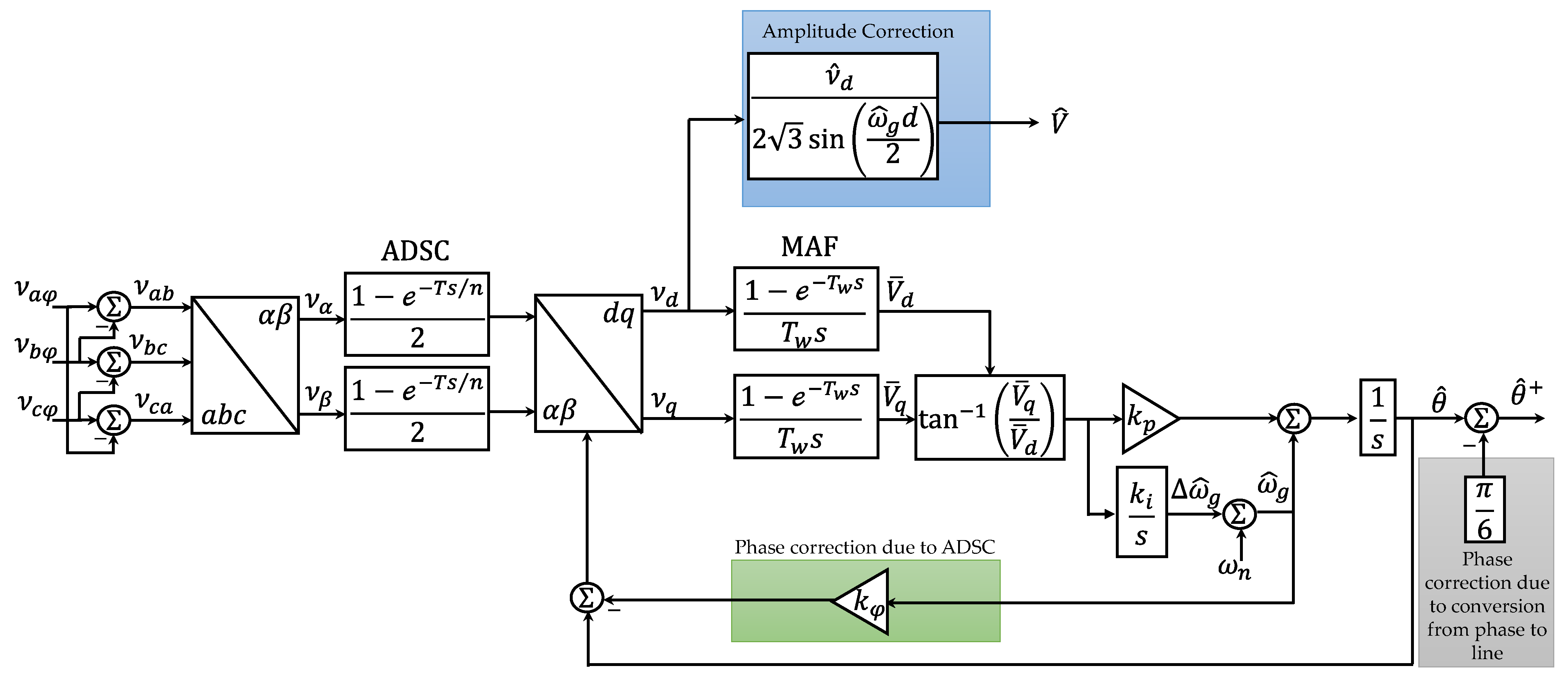
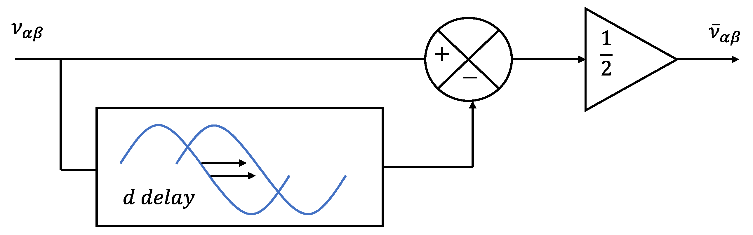
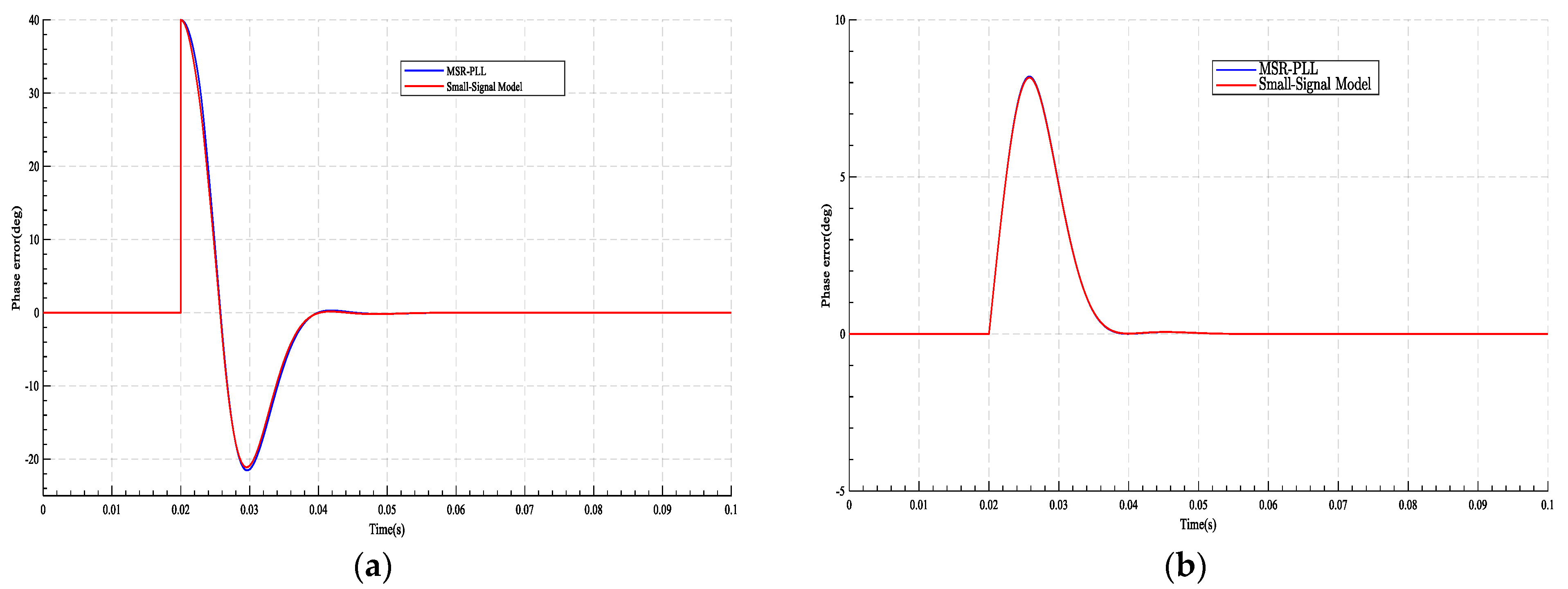
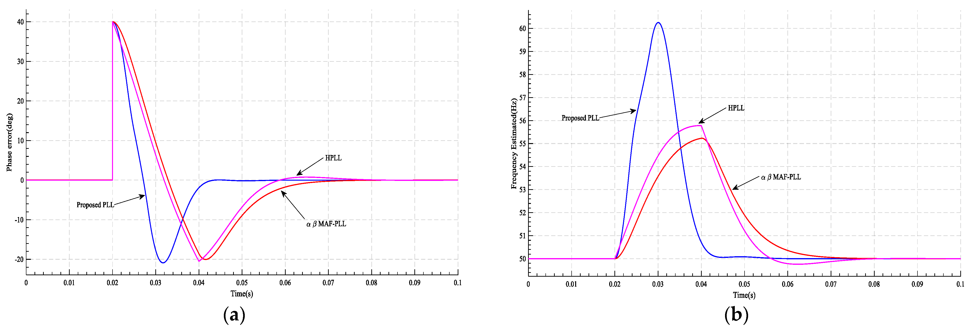
This paper proposes a new approach to design the loop filter (LF) of a third-order phase-locked loop (PLL), offering contributions in terms of the structural improvement of the three-phase PLL and a method for the optimal loop filter design. Without loss of generality, the proposed PLL combines an MAF with an arbitrarily delayed signal cancellation (ADSC) for structural enhancement to achieve DC-offset rejection and harmonics elimination. The window length of the MAF is selected to be one-sixth of the fundamental grid period to remove non-triple odd harmonics and accelerate the PLL response. The triple harmonics are eliminated, adopting the line-to-line voltage concept, while the ADSC operator rejects the effect of the DC offset. Moreover, different optimization methods are adopted to design the gains of the LF targeting the 2% criterion settling time in grid frequency deviation. The effectiveness of the proposed PLL and the adopted loop filter design method is verified by comparing their performance with other related PLLs and verifying the offered improvements numerically and experimentally.
2. The Proposed Method
2.1. PLL Structure Enhancement
PLL structure improvement includes the phase-to-line voltage transformation to block the triple harmonics. The ADSC, which is not restricted to a specific time delay, blocks the DC offset and the MAF with a window length of one-sixth of the fundamental grid period to block the non-triple odd harmonics.
The schematic diagram of the proposed PLL is shown in Figure 1, where , , and are the phase voltages; , , and are the line voltages; is the nominal angular frequency; is the phase error correction; is the deviation in the estimated grid frequency; is the estimated phase angle; is the estimated grid frequency.
Figure 1.
The block diagram of the proposed PLL.
2.1.1. Elimination of Odd Triple Harmonics
Typically, the grid-connected converters’ phase at neutral voltage is a source of odd triple harmonics. Thus, a transformation to line voltage is adopted in the proposed PLL to eliminate the odd triple harmonics out of the box without any additional cost or complexity, allowing for the decrease in the MAF window length, hence speeding up the PLL dynamic response. To verify the elimination, assume the input voltages of three-phase has odd triple harmonics as:
where is the phase, is the amplitude of the grid voltage, and is the amplitude of the odd triple harmonics. After some mathematical simplification, (1) to (3) can be written as shown in (4) to (6).
It can be noticed from (4) to (6) that the conversion from phase to line voltages eliminates the odd triple harmonics. However, it is worth mentioning that this conversation adds a phase shift of rad and scales the magnitude by .
2.1.2. Moving Average Filter (MAF)
The MAF is a linear phase filter that is deemed as a low-pass filter (LPF) [27,28]. Its transfer function can be written as in Equation (7):
where is the window length of the MAF; the block diagram of the MAF in the discrete domain is shown in Figure 2 [13].
Figure 2.
The block diagram of the MAF.
In Figure 2, is the input signal, is the output signal, and is the number of samples within the nominal period. The transfer function in the discrete domain can be expressed as:
The magnitude and phase can be found by substituting (s = jω) into Equation (7)
The harmonic () positive-sequence harmonic in the αβ-frame is transformed into a harmonics order in the -frame. In addition, the () negative-sequence harmonic in the αβ-frame is transformed into a harmonic in the -frame, where is the order of harmonics, and is the nominal grid frequency. Therefore, the most common αβ harmonics that appear in the input voltages of , , , , , and are transferred , , and in the -frame.
Based on Equation (9), the MAF has a unity gain at zero frequency and zero gains at frequencies = . The harmonics rejection in the MAF is associated with its window length, which is adjusted to trade-off between noise reduction and response time, depending on the application’s specific requirements. If the window length equals the nominal period, the DC-offset and the harmonics are rejected. In contrast, only odd harmonics are rejected if the window length is half the nominal period. The non-triple odd harmonics are rejected if the window length is adjusted to one-sixth of the nominal period [27]. This work adopts the window length of the sixth fundamental grid period allowing the PLL to block the non-triple odd harmonics while the line voltage blocks the triple harmonics.
2.1.3. Arbitrary Delayed Signal Cancellation (ADSC)
The ADSC blocks the DC offset in the αβ reference frame [11,23]. It is represented in (10) and shown in Figure 3.
where is the time delay in s, T is the nominal grid period, and n is an arbitrary positive number. The transfer function of the ADSC can be expressed as in (11).
which has the following magnitude and phase in the frequency domain:
Figure 3.
The block diagram of the ADSC operator.
2.1.4. Mathematical Model
The grid line voltages can be written as
where , , , and . is the fundamental grid frequency; is the phase angle; and are the initial phase angles of FFPS and FFNS, respectively; and are the initial phase angles of positive-sequence and negative-sequence harmonics, respectively; and are the amplitudes of FFPS and FFNS, respectively; and are the amplitudes of positive-sequence and negative-sequence harmonics, respectively. , , and are the amplitudes of the DC offset components. Now, to convert from -frame to -frame:
where
The DC components are canceled after using arbitrary delay signal cancellation (ADSC).
where is the DC-offset component, and are the other components of .
Now, to convert from -frame to -frame:
where
is the transformation matrix, and . Based on Equation (20), is zero and the amplitude is scaled by . Moreover, the ADSC introduces a phase shift that can be corrected through feedback. In addition to that, the line-to-line transformation introduces a phase of that can be simply subtracted from the estimated phase to compensate for it, as shown in Figure 1. The is multiplied by to compensate for the amplitude.
2.1.5. Small-Signal Model
The small-signal model can be written using and substituting into (20).
After some approximations, with some trigonometric identities and using the MAF transfer function, can be expressed as in Equation (22).
The small-signal model of the proposed method is shown in Figure 4.
Figure 4.
The block diagram of the small-signal model for the proposed PLL.
2.2. The Loop Filter Design
The LF is designed based on a modified third-order polynomial (25), in which the polynomial coefficients are tuned using stochastic optimization with the objective function and constraints to minimize the settling time of the frequency deviation.
The stability of the modified polynomial is determined using the Routh–Hurwitz criterion, from which the coefficients of the modified polynomial must obey the following conditions:
Based on the small-signal model, the closed-loop transfer function is shown in (29):
Comparing (25) with the characteristic equation of (29), and can be rewritten in terms of the coefficients of the modified polynomial as:
where is the window length, is the phase delay, and and determine the optimum parameter of the LF proportional-integral (PI)-gains. The optimization formulation is shown in (32). The flowchart that summarizes the optimization process is shown in Figure 5.
where the objective function () is the settling time () of the frequency deviation, OS is the overshoot, and and are the coefficients’ boundaries that are selected to be and .
Figure 5.
Flow chart of the optimization method.
Different optimization methods were investigated for the selection of the coefficients and : Particle swarm optimization (PSO), genetic algorithm (GA), bee algorithm (BA), and cuckoo optimization algorithm (COA) [29,30,31]. The results of the aforementioned optimization methods are shown in Table 1.
Table 1.
Optimization method comparison.
The results of the COA optimum parameters are adopted without loss of generality. The corresponding PI-controller gains for all values are listed in Table 2. It can be noticed that is constant for any . This is because (30) depends on the window length and the coefficient only, which is a constant independent of .
Table 2.
The optimum PI-controller.
Figure 6 shows the response of the actual model along with its small-signal model under a phase jump and a 6 Hz frequency jump from a 50 Hz grid frequency, validating the small-signal model in predicting the response of the actual PLL at a distinct phase delay.
Figure 6.
The proposed PLL and its small-signal model at t = 0.02 s under (a) + at and (b) Hz at .
3. Simulation Results
The performance of the utilized PLL adopting the proposed third-order optimized polynomial with DC-offset and harmonics rejection is verified using numerical simulation. It is compared with MAF-PLL [13] and hybrid-PLL (HPLL) [15]. The nominal grid frequency is , and the parameters of the compared PLLs are summarized in Table 3, while the grid harmonics are listed in Table 4. Several case studies were considered for a fair comparison, as shown below:
Table 3.
Control parameter values.
Table 4.
Parameters of distortion in input voltage.
- Case 1: A phase jump of at 0.02 s and , and . The results are shown in Figure 7, Figure 8 and Figure 9, respectively, and summarized in Table 5.
Figure 7. The results of case 1 at and at t = 0.02 s: (a) PLL’s phase error; (b) the frequency estimated by PLL.
Figure 8. The results of case 1 at and at t = 0.02 s: (a) PLL’s phase error; (b) the frequency estimated by PLL.
Figure 9. The results of case 1 at and at t = 0.02 s: (a) PLL’s phase error: (b) the frequency estimated by PLL.
Table 5. The results of case 1 (Phase Jump). - Case 2: A frequency jump in the grid from 50 to 56 Hz at 0.02 s and , and . The results are shown in Figure 10, Figure 11 and Figure 12, respectively, and summarized in Table 6.
Figure 10. The results of case 2 at and at t = 0.02 s: (a) the frequency estimated by PLL; (b) PLL’s phase error.
Figure 11. The results of case 2 at and at t = 0.02 s: (a) the frequency estimated by PLL; (b) PLL’s phase error.
Figure 12. The results of case 2 at and at t = 0.02 s: (a) the frequency estimated by PLL; (b) PLL’s phase error.
Table 6. The results of case 2 (Frequency Jump). - Case 3: Only DC-offset is added to the grid voltage by 0.1 pu of phase a, −0.1 of phase b, and 0.05 of phase c at 0.02 s, and , and . The results are shown in Figure 13, Figure 14 and Figure 15, respectively, and summarized in Table 7.
Figure 13. The results of case 3 at and at t = 0.02 s; (a) the frequency estimated by PLL; (b) PLL’s phase error.
Figure 14. The results of case 3 at and at t = 0.02 s: (a) the frequency estimated by PLL; (b) PLL’s phase error.
Figure 15. The results of case 4 at and at t = 0.02 s: (a) the frequency estimated by PLL; (b) PLL’s phase error.
Table 7. The results of case 3 (DC-Offset). - Case 4: A frequency jump of 5 Hz with DC-offsets similar to case three with harmonics, listed in Table 4, is added at 0.02 s for , and . The results are shown in Figure 16, Figure 17 and Figure 18, respectively, and summarized in Table 8.
Figure 16. The results of case 4 at and t = 0.02 s: (a) the frequency estimated by PLL; (b) PLL’s phase error.
Figure 17. The results of case 4 at and t = 0.02 s: (a) the frequency estimated by PLL; (b) PLL’s phase error.
Figure 18. The results of case 4 at and t = 0.02 s: (a) the frequency estimated by PLL; (b) PLL’s phase error.
Table 8. The results of case 4 (Frequency Jump with Harmonics and DC-Offset).
4. Discussion
Table 5, Table 6, Table 7 and Table 8 summarize the performance comparisons between the proposed PLL, the αβMAF-PLL, and HPLL. The comparison is made considering the phase settling time, the frequency settling time, the overshoot, the estimated frequency peak, and the phase error peak. In the first case, it can be noticed that the proposed PLL has the fastest dynamic response reaching the steady state in less than 0.02 s for any delay factor except for which it needs about 1.1 grid cycles, while the other PLLs need about two grid cycles to settle down. The phase percent overshoot is slightly better than those of the other methods. In the case of frequency jump, the proposed PLL has the fastest dynamic response and reaches the steady state in less than one grid cycle without overshooting for any delay factor. Concerning DC offset, the proposed method rejects the DC offset two times faster than the other methods. The peak frequency and phase errors are almost the same as the other methods. In the last case—the frequency jump with DC-offset and harmonics—the proposed PLL achieves the fastest response with less peak phase error with respect to other methods, synchronizing with the grid in a fraction of a grid cycle.
5. Experimental Verification
To demonstrate the performance enhancement of the proposed PLL and the LF design with comparisons to HPLL and αβMAF-PLL, digital implementation of all the PLLs is made utilizing the DE2-115 development and education board from Altera. An AC power supply is used to generate the voltage signal. The experiment maintains the grid voltage amplitude (V) and sampling frequency () at 1 pu and 10 kHz, respectively. The nominal grid frequency is 50 Hz. The results are captured using RIGOL MSO5354 mixed-signal oscilloscopes. Two cases are considered adopting without loss of generality.
- Case A: From the ideal grid condition, three disturbances occur simultaneously, including the dominant harmonics listed in Table 4 with DC-offset (0.1 pu to phase a, −0.1 pu to phase b, and 0.05 pu to phase c) and a frequency jump by 6 Hz. The results of the phase error and the estimated grid frequency of all the PLLs are shown in Figure 19.
Figure 19. The results under case A: (a) the phase error and (b) the estimated grid frequency. - Case B: The frequency jump in case A is replaced by a phase jump of 45° while keeping the harmonic and DC-offset. The results of the phase error and the estimated grid frequency of all the compared PLLs are shown in Figure 20.
Figure 20. The results of case B: (a) PLL’s phase error and (b) the estimated grid frequency.
The experimental results agree with the simulation, which validates the proposed method.
6. Conclusions
A new approach for designing the loop filter of a third-order phase-locked loop is proposed in this paper. The proposed PLL consists of a moving average filter and an arbitrarily delayed signal cancelation. The arbitrary delay signal cancelation blocks the DC offset. In contrast, the moving average filter, with a window length of one-sixth of the fundamental grid period, blocks non-triple odd harmonics. The remaining triple harmonics are blocked utilizing the line voltage. The loop filter design is based on a modified third-order polynomial derived from stochastic optimization with the settling time of the frequency deviation as the objective function. The effectiveness of the proposed PLL and the adopted loop filter design method is verified by comparing their performance with other related PLLs, demonstrating the offered improvements. The simulation and experimental results show that the proposed PLL achieves synchronization within one grid cycle two times faster than the other PLLs. Therefore, the proposed PLL can be used to ensure that the renewable energy source can be safely and efficiently integrated into the grid.
Author Contributions
Conceptualization, I.A.S.; Software, H.A.K.; Validation, I.A.S. and H.A.K.; Investigation, H.A.K. and I.E.A.; Writing—Original Draft, H.A.K.; Writing—Review and Editing, I.A.S. and I.E.A.; Visualization, I.E.A.; Supervision, I.A.S.; Funding Acquisition, I.E.A. All authors have read and agreed to the published version of the manuscript.
Funding
This research received no external funding.
Data Availability Statement
Not applicable.
Conflicts of Interest
The authors declare no conflict of interest.
References
- Yang, L.; Cao, T.; Chen, H.; Dong, X.; Zhang, S. Robust Control and Optimization Method for Single-Phase Grid-Connected Inverters Based on All-Pass-Filter Phase-Locked Loop in Weak Grid. Energies 2022, 15, 7355. [Google Scholar] [CrossRef]
- Stojić, D. Improved observer-based quadrature signal generator. Electr. Eng. 2021, 103, 3063–3073. [Google Scholar] [CrossRef]
- Luhtala, R.; Alenius, H.; Roinila, T. Practical Implementation of Adaptive SRF-PLL for Three-Phase Inverters Based on Sensitivity Function and Real-Time Grid-Impedance Measurements. Energies 2020, 13, 1173. [Google Scholar] [CrossRef]
- Chahine, K.; Tarnini, M.; Moubayed, N.; El Ghaly, A. Power Quality Enhancement of Grid-Connected Renewable Systems Using a Matrix-Pencil-Based Active Power Filter. Sustainability 2023, 15, 887. [Google Scholar] [CrossRef]
- Aldbaiat, B.; Nour, M.; Radwan, E.; Awada, E. Grid-Connected PV System with Reactive Power Management and an Optimized SRF-PLL Using Genetic Algorithm. Energies 2022, 15, 2177. [Google Scholar] [CrossRef]
- Wang, Z.; Fu, P.; Huang, L.; Chen, X.; He, S.; Zhang, X.; Yang, J. Performance improvement of a three-phase PLL under distorted grid conditions based on frequency adaptive hybrid prefiltering. IET Power Electron. 2022, 5, 1429–1440. [Google Scholar] [CrossRef]
- Luo, W.; Wei, D. A frequency-adaptive improved moving-average-filter-based quasi-type-1 PLL for adverse grid conditions. IEEE Access 2020, 8, 54145–54153. [Google Scholar] [CrossRef]
- Wang, J.; Liang, J.; Gao, F.; Zhang, L.; Wang, Z. A method to improve the dynamic performance of moving average filter-based PLL. IEEE Trans. Power Electron. 2014, 30, 5978–5990. [Google Scholar] [CrossRef]
- Smadi, I.A.; Fawaz, B.H.B. Phase-locked loop with DC offset removal for single-phase grid-connected converters. Electr. Power Syst. Res. 2021, 194, 106980. [Google Scholar] [CrossRef]
- Garg, R.; Mahajan, P. Control of Grid Integrated Photovoltaic system using new Variable Step Size Least Mean Square adaptive filter. Electr. Eng. 2021, 103, 2945–2959. [Google Scholar]
- Smadi, I.A.; Sultan, W. A phase-locked loop with an improved dynamic response under abnormal grid conditions. Comput. Electr. Eng. 2022, 97, 107645. [Google Scholar] [CrossRef]
- Xie, M.; Zhu, C.; He, L.; Wen, H. An experimental study of MAF-SRF-PLL with comb compensator. In Proceedings of the 2017 IEEE Applied Power Electronics Conference and Exposition (APEC), Tampa, FL, USA, 26–30 March 2017; pp. 1310–1313. [Google Scholar]
- Li, J.; Wang, Q.; Xiao, L.; Hu, Y.; Wu, Q.; Liu, Z. An αβ-Frame Moving Average Filter to Improve the Dynamic Performance of Phase-Locked Loop. IEEE Access 2020, 8, 180661–180671. [Google Scholar] [CrossRef]
- Golestan, S.; Freijedo, F.D.; Vidal, A.; Guerrero, J.M.; Doval-Gandoy, J. A quasi-type-1 phase-locked loop structure. IEEE Trans. Power Electron. 2014, 29, 6264–6270. [Google Scholar] [CrossRef]
- Golestan, S.; Guerrero, J.M.; Abusorrah, A.M.; Al-Turki, Y. Hybrid synchronous/stationary reference-frame-filtering-based PLL. IEEE Trans. Ind. Electron. 2015, 62, 5018–5022. [Google Scholar] [CrossRef]
- He, X.; Liu, M.; Li, Y.; Hong, F.; Yang, J.; Jiang, F. Synchronous Reference Frame Paralleled MAF/DSC-Based PLL. In Proceedings of the 2020 Asia Energy and Electrical Engineering Symposium (AEEES), Chengdu, China, 29–31 May 2020; pp. 361–364. [Google Scholar]
- Golestan, S.; Guerrero, J.M.; Vasquez, J.C. A nonadaptive window-based pll for single-phase applications. IEEE Trans. Power Electron. 2017, 33, 24–31. [Google Scholar] [CrossRef]
- Wanchana, S.; Benjanarasuth, T.; Komine, N.; Ngamwiwit, J. PLL equivalent augmented system incorporated with state feedback designed by LQR. Int. J. Control Autom. Syst. 2007, 5, 161–169. [Google Scholar]
- Niu, X.; Li, B.; Ziedan, N.I.; Guo, W.; Liu, J. Analytical and simulation-based comparison between traditional and Kalman filter-based phase-locked loops. GPS Solut. 2017, 21, 123–135. [Google Scholar] [CrossRef]
- Hamed, H.A.; Abdou, A.F.; Bayoumi, E.; EL-Kholy, E.E. Effective design and implementation of GSS-PLL under voltage dip and phase interruption. IET Power Electron. 2018, 11, 1018–1028. [Google Scholar] [CrossRef]
- Golestan, S.F.; Freijedo, F.D.; Guerrero, J.M. A systematic approach to design high-order phase-locked loops. IEEE Trans. Power Electron. 2014, 30, 2885–2890. [Google Scholar] [CrossRef]
- Smadi, I.A.; Bany Fawaz, B.H. DC offset rejection in a frequency-fixed second-order generalized integrator-based phase-locked loop for single-phase grid-connected applications. Prot. Control Mod. Power Syst. 2022, 7, 1. [Google Scholar] [CrossRef]
- Smadi, I.A.; Issa, M.B. Phase Locked Loop with DC-Offset Removal for Grid Synchronization. In Proceedings of the IECON 2019—45th Annual Conference of the IEEE Industrial Electronics Society, Lisbon, Portugal, 14–17 October 2019; Volume 1, pp. 4669–4673. [Google Scholar]
- Golestan, S.; Guerrero, J.M.; Vidal, A.; Yepes, A.G.; Doval-Gandoy, J. PLL with MAF-based prefiltering stage: Small-signal modeling and performance enhancement. IEEE Trans. Power Electron. 2015, 31, 4013–4019. [Google Scholar] [CrossRef]
- Kathiresan, A.C.; PandiaRajan, J.; Sivaprakash, A.; Sudhakar Babu, T.; Islam, M.R. An Adaptive Feed-Forward Phase Locked Loop for Grid Synchronization of Renewable Energy Systems under Wide Frequency Deviations. Sustainability 2020, 12, 7048. [Google Scholar] [CrossRef]
- Hui, N.; Wang, D.; Li, Y. A novel hybrid filter-based PLL to eliminate effect of input harmonics and DC offset. IEEE Access 2018, 6, 19762–19773. [Google Scholar] [CrossRef]
- Mellouli, M.S.; Hamouda, M.; Slama, J.B.H.; Al Haddad, K. A third-order MAF Based QT1-PLL that is robust against harmonically distorted grid voltage with frequency deviation. IEEE Trans. Energy Convers. 2021, 36, 1600–1613. [Google Scholar] [CrossRef]
- Golestan, S.; Guerrero, J.M.; Vasquez, J.C. Three-phase PLLs: A review of recent advances. IEEE Trans. Power Electron. 2016, 32, 1894–1907. [Google Scholar] [CrossRef]
- De Melo Menezes, B.A.; Herrmann, N.; Kuchen, H.; Buarque de Lima Neto, F. High-Level Parallel Ant Colony Optimization with Algorithmic Skeletons. Int. J. Parallel Program. 2021, 49, 776–801. [Google Scholar] [CrossRef]
- Panag, T.S.; Dhillon, J.S. A novel random transition based PSO algorithm to maximize the lifetime of wireless sensor networks. Wirel. Pers. Commun. 2018, 98, 2261–2290. [Google Scholar] [CrossRef]
- Roni, M.H.K.; Rana, M.S.; Pota, H.R.; Hasan, M.M.; Hussain, M.S. Recent trends in bio-inspired meta-heuristic optimization techniques in control applications for electrical systems: A review. Int. J. Dyn. Control 2022, 10, 999–1011. [Google Scholar] [CrossRef]
Disclaimer/Publisher’s Note: The statements, opinions and data contained in all publications are solely those of the individual author(s) and contributor(s) and not of MDPI and/or the editor(s). MDPI and/or the editor(s) disclaim responsibility for any injury to people or property resulting from any ideas, methods, instructions or products referred to in the content. |
© 2023 by the authors. Licensee MDPI, Basel, Switzerland. This article is an open access article distributed under the terms and conditions of the Creative Commons Attribution (CC BY) license (https://creativecommons.org/licenses/by/4.0/).