Article

Optimizing Well Completion for Polymer Flooding in Conjunction with Waterflood Flow Control Valves

by
Camilo Andrés Guerrero-Martin
1,2,*,
Miguel Ángel Moreno López
3,
Laura Isabel Vargas Vargas
3,
Elizabete F. Lucas
4,5,
Wanessa K. Lima e Silva
1,2,
Vando J. Costa Gomes
1,2,
Pedro Paulo de Freitas
1,2,
Raúl Salinas-Silva
1,6,
Stefanny Camacho-Galindo
1,6,
Laura Estefanía Guerrero-Martin
1,6 and
Rubén H. Castro
7,*
1
Grupo de Pesquisa em Energia e Mar, Faculty of Engineering, Federal University of Pará, Salinópolis 68721-000, PA, Brazil
2
Department of Engineering, Federal University of Pará—Campus Salinópolis, Rua Raimundo Santana Cruz, S/N, Bairro São Tomé, Salinópolis 68721-000, Brazil
3
Department of Energy, Universidad de América, Bogotá 110311, Colombia
4
Laboratório de Macromoléculas e Coloides na Indústria do Petróleo, Instituto de Macromoléculas, Universidade Federal do Rio de Janeiro, Rio de Janeiro 21941-594, RJ, Brazil
5
Laboratório de Aditivos Poliméricos Para Produção de Petróleo, Programa de Engenharia Metalúrgica e de Materiais, COPPE, Universidade Federal do Rio de Janeiro, Rio de Janeiro 21941-594, RJ, Brazil
6
Fundación de Educación Superior San José, Usanjose, Bogotá 110311, Colombia
7
Grupo de Investigación en Fenómenos de Superficie—Michael Polanyi, Facultad de Minas, Universidad Nacional de Colombia—Sede Medellín, Medellín 050034, Colombia
*
Authors to whom correspondence should be addressed.
Energies 2023, 16(22), 7565; https://doi.org/10.3390/en16227565
Submission received: 25 June 2023 / Revised: 4 October 2023 / Accepted: 18 October 2023 / Published: 14 November 2023

Abstract

:
This work presents the proposal design for the completion of a polymer flooding injector well with waterflood flow regulator valves (FRV) in a Colombian field, based on experimental evaluations at the laboratory, intending to reduce the mechanical degradation suffered by the polymer solution at the time of injection, which allows to maintain the design parameters of the improved recovery project and reach the expected recovery factor. An analysis of the parameters and variables that influence the mechanical degradation of the polymer solution during the injection process (polymer solution concentration and the diameters of the FRV) was carried out using one laboratory methodology based on the recommended practices for the evaluation of polymers used in enhanced oil recovery operations API RP63. This work focuses on the following highlights: Evaluation of a waterflood flow regulator valve through experimental tests for polymer flooding and the designing of an initial well completion strategy to minimize mechanical degradation. The proposed valve and diameter resulted in a reduction of only 15 percentage points in the mechanical degradation of the polymeric solution when compared to a commercial water valve.

1. Introduction

The significant global demand for oil is driving the industry to revitalize matureoil fields through the implementation of enhanced oil recovery (EOR) projects [1,2]. There are three main methods of recovery: primary recovery, which involves extracting the oil using the reservoir’s natural pressure; secondary recovery, where water or gas is injected to increase reservoir pressure and force oil to the surface; and tertiary recovery, which involves injecting fluids other than those naturally present in the reservoir, such as chemical agents like surfactants, to improve the mobility of the oil and increase the recovery factor [3,4]
During the secondary recovery process, the permeability of the reservoirs tends to decline [5,6]. As a result, the injected fluid tends to flow preferentially through certain areas, leading to oil losses in the porous medium and the formation of channels [6]. This results in low oil recovery and unfavorable economic outcomes [7]. To address this problem, the injection of polymers is one of the most used EOR methods, providing good recovery and increasing areal and vertical sweep efficiency by promoting a more uniform displacement front [8,9].
This method involves injecting polymers into the reservoir to increase the viscosity of the water and improve the mobility of the oil [10,11]. Under pressure, the polymer is injected into the oil well in an aqueous solution, which is then pumped into the reservoir [12]. The polymer dissolves in the water, forming a high molecular weight solution that increases viscosity [13]. The principle behind this method is mobility control, which improves the interaction between the displacing fluid and the oil. However, the criteria for polymer injection and its efficiency depend entirely on reservoir conditions, such as lithology, temperature, salinity, permeability, and others [14].
Furthermore, depending on the type of polymer used, the effective permeability for oil remains relatively unchanged while the effective permeability of the reservoir rock for the aqueous phase is reduced [15]. This reduction occurs due to the adsorption of polymer molecules onto the mineral surface of the rock, and it is considered a non-reversible process. Therefore, even with subsequent water injection, the reduction in effective permeability persists [16].
Although not always active in recovering oil under certain reservoir conditions, xanthan gum and partially hydrolyzed polyacrylamide (HPAM) are among the polymers most frequently used by the industry due to their common commercial prospects in the oil industry. By increasing the viscosity of water, these polymers direct the injected fluid to areas with lower permeability, filling the pores of the medium and mitigating the preferential flow of fluids along paths with higher permeability. As a result, there is an increase in the sweep efficiency of oil [17] (This method leads to the anticipation of oil production and reduces costs associated with the treatment of produced water, making polymeric solution injection more viable than water injection in many cases.
There are three classifications for types of polymer injection: (a) Polymer injection by gravity: In this method, the polymer is added to the reservoir, and then gravity is allowed to mix the polymer with the water [18]. (b) Polymer injection by pressure: For this method, the polymer is added to the reservoir and then pumped into the reservoir using a pressure pump. This ensures even mixing of the polymer with the water [19]. (c) Polymer injection via a dispersion system: Here, the polymer is added to the reservoir and then dispersed using a dispersion system. This allows the polymer to be evenly mixed with the water [20].
Polymer flooding is a widely used EOR method in the world. In Colombia, different pilot projects of this EOR method have been carried out in some oil fields [21]. This is largely due to the low cost process, the availability of the motive fluid, and the oil displacement efficiency [22].
However, the success of polymer flooding process depends mainly on the mobility ratio control that this exerts in the reservoir [23,24], and in turn, this of the adequate viscosity of the injected polymeric solution, as its stability is affected by different factors such as chemical, thermal, biological, or mechanical degradation [25,26], throughout the entire cycle of the injection process, from its preparation on the surface facilities to the displacement in the reservoir [27].
Mechanical degradation is one of the kinds of polymer degradation to which the solution is exposed during the injection process [28,29]. This occurs because the polymer presents a plastic deformation generated by internal friction in an area of high flow associated with abrupt pressure drops [30,31]. In the fluid path in the tubing from the surface to bottom, mechanical degradation occurs by the different accessories like valves and completion components [32,33] since at these points there is an increasing shear rate, which generates a decrease in the viscosity of the solution by polymer chains fractures (Table 1) [34,35].
It is necessary to evaluate the pressure drop points to which the polymeric solution will be subjected throughout the injection string to determine the most suitable configuration of the well completion state, considering the conditions of the injection process according to the operational parameters in the oil field (a type of polymer, concentration, flow rates, and injected volumes).

2. Materials and Methods

2.1. Parameters That Influence the Mechanical Degradation of Polymer Solution

It is observed that the polymer solution tends to vary its viscosity in the presence of shear stresses, which elongate the polymer in an elastic behavior until reaching the maximum deformation rate allowed, that is, the maximum shear stressed the point that the polymer bears according to its design, from which it deforms and exhibits plastic behavior [38].
The polymer’s shear rate is affected by a series of variables that have been studied over time by various authors and these in turn influence the polymer’s mechanical degradation [39,40]. For the case study, it is determined that an experimental design will consist of the evaluation of the polymeric solution viscosity at different concentrations and diameters of injection flow control valves (which is the critical point deformation of the polymeric solution).
The methodology used is based on the API RP63. The procedures were considered for the preparation of the stock solution, the dilutions, the viscosity measurement of each sample, and the mechanical degradation test, varying the concentration of the solution and the diameters of the valves.

2.2. Laboratory Study

The experimental study was carried out which allowed simulation of the FRV conditions for polymer flooding in a Colombian oil field. The polymer employed was a commercial sulfonated polyacrylamide with a molecular weight of 4–6 million g/mol.

2.2.1. Equipment

  • Lab digital scale. To weigh the raw materials required in the preparation of polymer solutions;
  • Beakers. Transparent glass containers were used for the storage of the samples during the process;
  • Mixer. Main equipment for agitation during sample preparation;
  • Brookfield Viscometer. Used for recording the viscosity of samples before and after shearing through the FRV;
  • Mechanical degradation equipment.

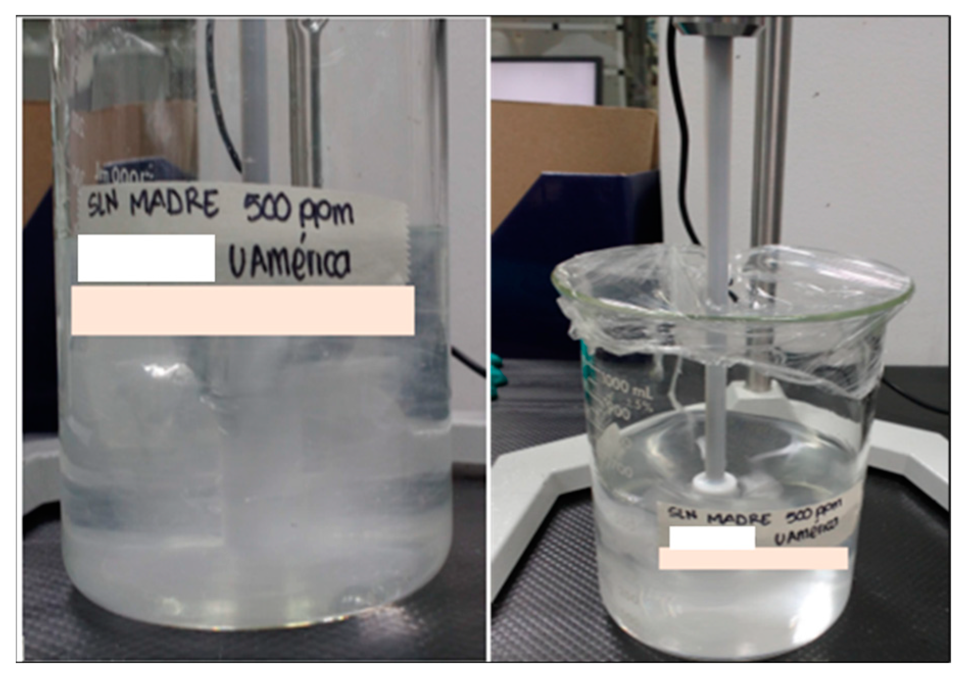
2.2.2. Preparation of the Stock Polymeric Solution from Dried Polyacrylamide Products

Stock solution from dry polyacrylamide products. Under literals 2.2.2, 2.3.3, and 2.3.4 of API RP63 [41], dry polyacrylamide solutions are generally prepared as a stock solution (approximately 5000 ppm) and diluted to test concentrations as required. Vigorous agitation is necessary for the initial dispersion of the dry powder. Concentrated polyacrylamide solutions can be stored at room laboratory temperature in brown glass bottles for 2 to 3 weeks without loss of effectiveness.

2.2.3. Preparation of Dilute Polymeric Solutions from the Polyacrylamide Stock Solution

Polymer solutions from the polyacrylamide stock solution. According to numeral 2.2.1 of the API RP 63 standard, polyacrylamide stock solutions are highly viscous fluids that vary according to the dissolved polymer content, so they must be handled properly when preparing dilute solutions in the laboratory. Likewise, during the procedure, the same type of water is used which works in the field, and the correct amount of stock solution is added according to the concentration needed.

2.2.4. Viscosity Measurement Procedures Using a Low-Viscosity-Adapted Digital Viscometer

These measurements are carried out using a digital viscometer adapted for low viscosities. To measure this process variable, it is necessary to take a sample of the polymer solution sheared or without shearing and provide a minimum volume of the polymer solution of 40 mL to achieve repeatability of the viscosity measurement. Viscosity should be measured in Brookfield equipment at a speed of 6 rpm, a shear rate of 7.3 s−1, and a temperature of 30 °C.

2.2.5. Evaluation of the Mechanical Degradation of Polymer Solutions with VRF

The mechanical degradation test simulates the shear stress suffered by the polymer solution due to its flow through a spring-type FRV; for this, the polymer solution is pressurized to pass through a capillary tube at a specific flow rate, which will cause a shear stress estimated due to the passage of fluid through the equipment used in the injection well.
Shear rates can be calculated by recording the fluid flow rates through the assembly as well as this allows different scenarios to be evaluated by changing the concentration of the polymer solution and by varying the diameter of the FRV.
For the mechanical degradation test, there is an assembly proposed by the API RP63, and adapted by [42]. In this case, the objective is to evaluate the mechanical degradation of polymer solutions through the FRV with different diameters (instead of the capillary). Figure 1 shows the scheme.
The piston-type cylinder works as a storage tank for the polymeric solution. It has an internal plunger that is pneumatically actuated by the nitrogen released from the bullet, causing the solution to flow through different diameters of FRV (with a pressure drop in the system of 100 psi).
The FRV is responsible for regulating the flow that is being injected by varying the diameter of an internal regulator. The pressure drop generated in the mechanism uniformly maintains the flow rate of the fluid that passes through it; however, in a polymer injection process, these accessories are those that are most associated with the degradation of the solution (because they are designed for water injection processes). For this reason, they are the central point of evaluation of this work. There are different FRV configurations for waterflooding and the polymer flooding process, however, the spring type was used.

2.3. Determination of Mechanical Degradation

A percentage is determined by considering the viscosities of the polymer solution measured before and after shearing, as well as the viscosity of the preparation water (0.74 cP and 30 °C) and applying the following formula of mechanical degradation (Equation (1)) [37],
D e g   ( % ) = μ _ S h e a r e d μ _ i n i t i a l μ _ i n i t i a l μ _ H 2 O 100

2.4. Recommendation of the Configuration of the Mechanical State for Optimal Well Completion

The laboratory results are used to determine the optimum diameter of the FRV configuration to be installed in the polymer injector well for a guaranteed mechanical degradation of less than 15%.

3. Results and Discussion

3.1. Laboratory Study

3.1.1. Preparation of Polymer Solutions

Polymer solutions were prepared to be used for the water injection of the study field. For the experimental setup in the laboratory, dilutions were made at 300, 500, and 1000 ppm from the stock solution that was previously prepared (5000 ppm).
Figure 2 shows the photographic record of the preparation of the polymer solution.
At the beginning of the stirring, the speed is adjusted so that the vortex extends 75% in the solution (approx. 200 rpm). Polymer is sprinkled on the shoulder of the vortex using a continuous blow for of 30 s, and no large lumps or “fisheyes” are observed. The change from Newtonian fluid to pseudoplastic with the inversion of the vortex is observed in this procedure.
The solution is left under continuous stirring to allow it to hydrate overnight (approx. 12 h). The next day it is checked to ensure that there is no presence of undissolved particles.

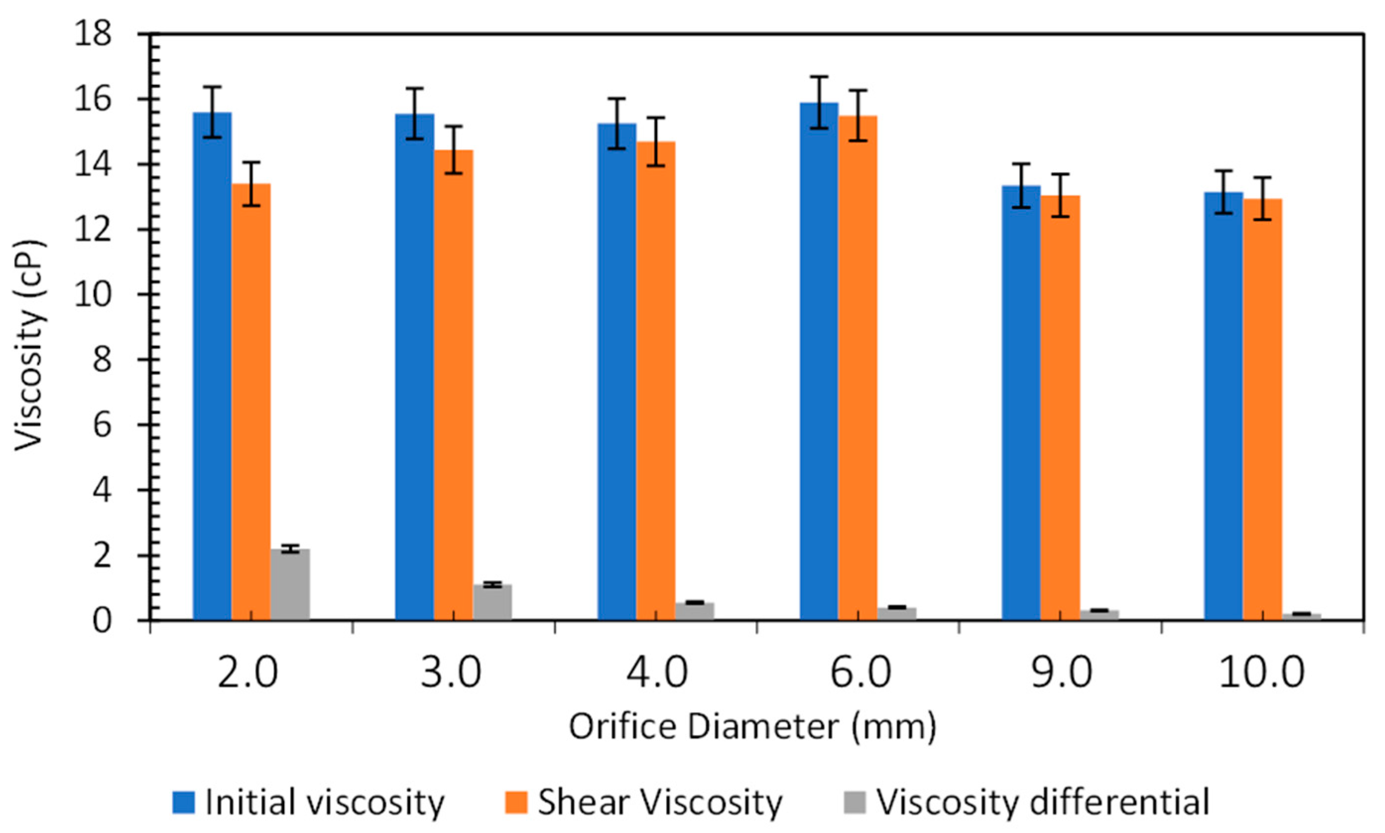
3.1.2. Viscosity Measurements of the Polymer Solutions

Polymer viscosity sheared or without shear should be measured (in duplicate) in Brookfield equipment at a speed of 6 rpm, a shear rate of 7.3 s−1, and a temperature of 30 °C.

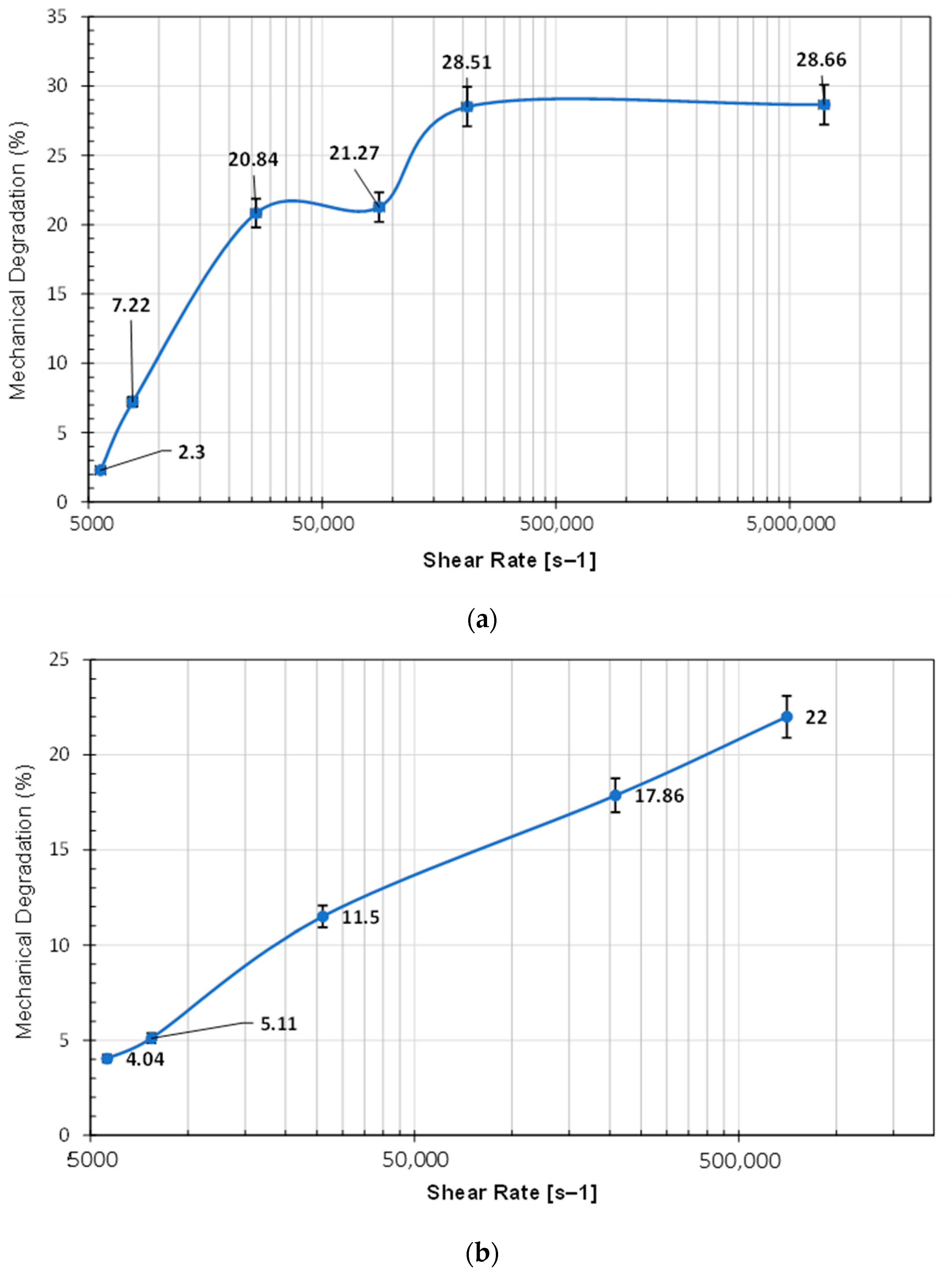
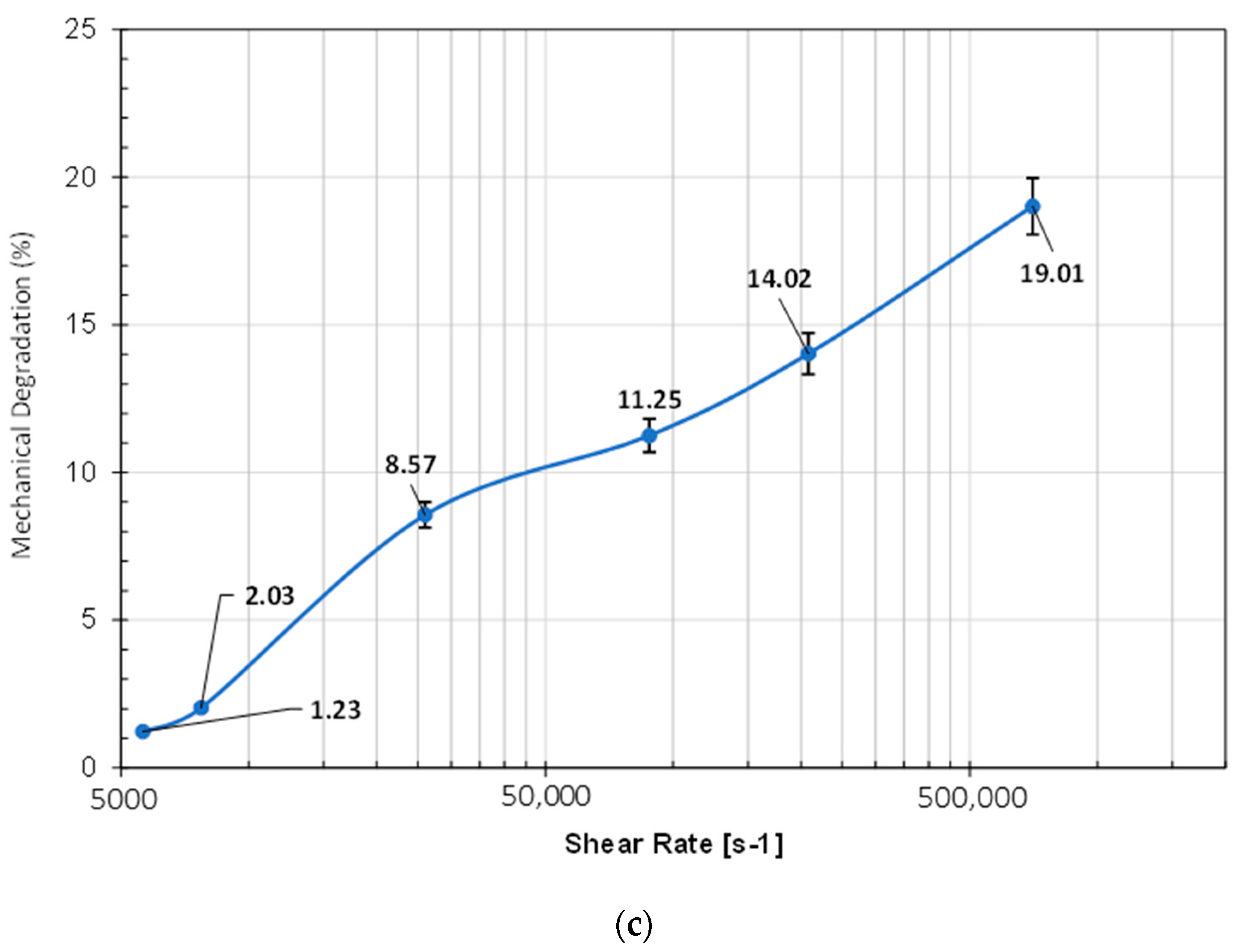
3.1.3. Mechanical Degradation Test

Laboratory experimental tests were carried out for the evaluation of the polymeric solutions through the flow regulator valve based on 2, 3, 6, 9, and 10 mm diameters.

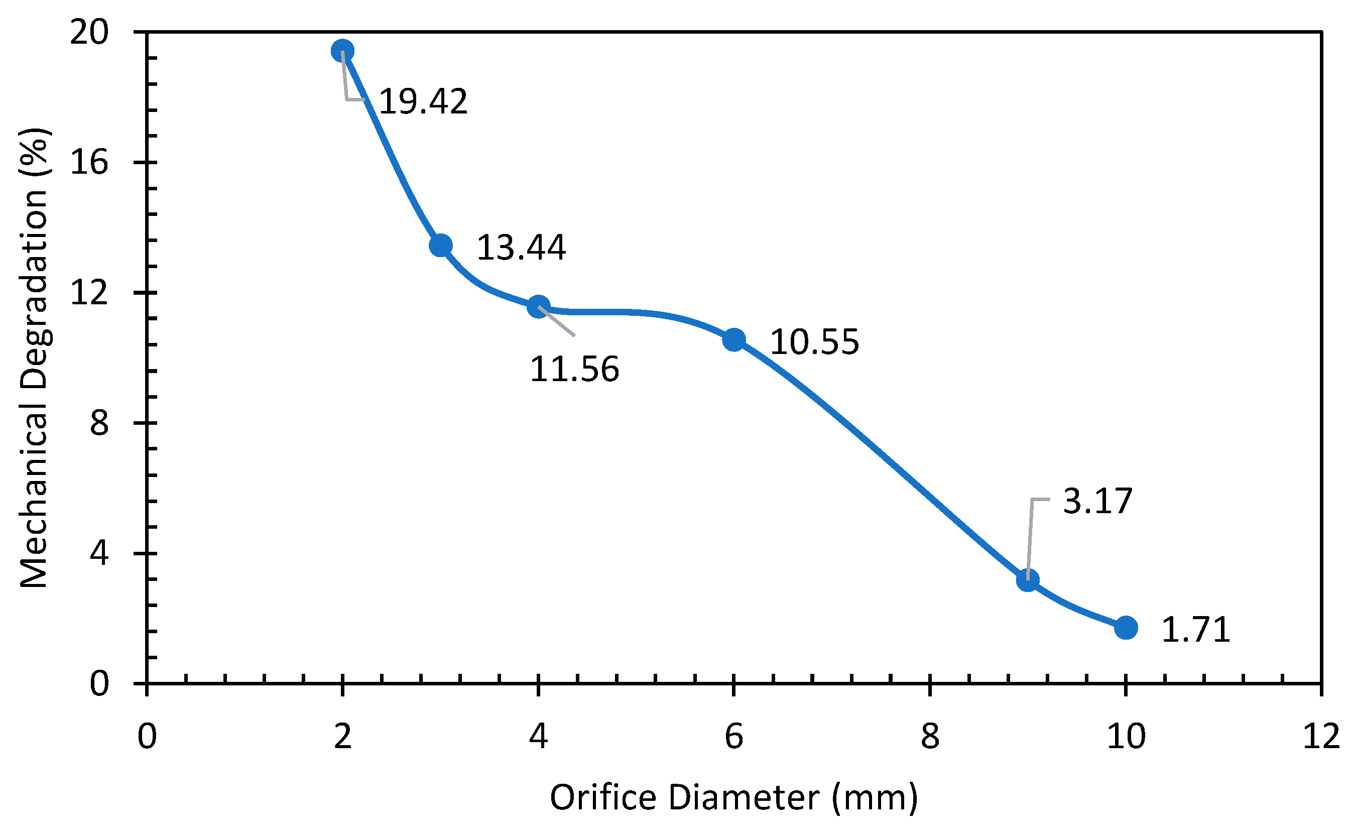
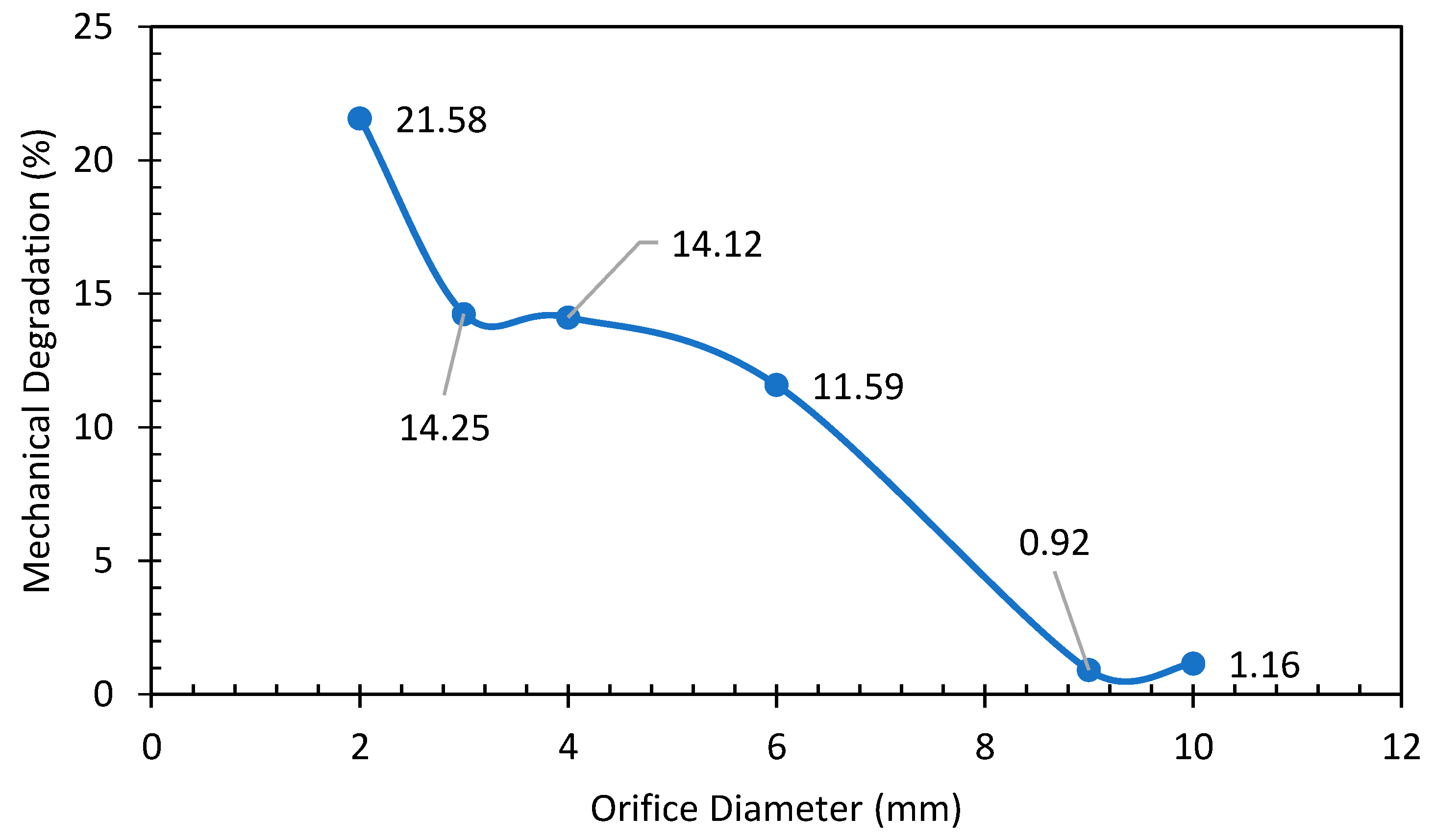
3.1.4. Determination of Mechanical Degradation

Table 2 presents the tabulation of experimental results. The results obtained are first classified by concentration and then according to diameters evaluated (with a pressure drop in the system of 100 psi).
Upon data collection from each conducted test, mechanical degradation of the polymer solution was quantified through calculations. The laboratory-scale experiments employed a spring-type valve. The resulting experimental data were organized into a tabular format, classifying the samples into three primary categories corresponding to the examined concentrations (300, 500, and 1,000 ppm). For each concentration level, data were collected for five different valve diameters (2, 3, 4, 9, and 10 mm) (see Table 3).
On the other hand, laboratory tests offer a higher degree of data control due to the precise preparation of the polymer solution and viscosity measurements within a controlled environment. However, certain limitations arise during these tests due to assembly conditions, including pressure and low constraints. The pressures, flow rates, polymer cylinder volume, and pumping conditions impose limitations on the flow rate of the solution through the flow regulating valve. Increasing the flow rate would necessitate enlarging the polymer cylinder and the nitrogen bullet to boost the test’s pressure. Nevertheless, a larger measurement volume could introduce errors in flow rate calculations, even with an increased deformation rate. The test evaluates the pressure at 600 psi with a pressure differential of 100 psi.
The subsequent graphs depict mechanical degradation and viscosity alterations of polymer solutions across various concentrations evaluated using a spring-type flow control valve, each tested at different diameters. Figure 3 and Figure 4 show the behavior of percentage and the viscosity for a 300 ppm solution.
The results are consistent with theoretical expectations, indicating an inverse relationship between mechanical degradation and pipe diameter. In other words, smaller diameters exhibit higher degradation percentages. Similarly, it is evident that viscosity loss after shearing decreases as the diameter of the flow regulating valve (FRV) increases.
Figure 5 and Figure 6 show the behavior of percentage and the viscosity for a 300 ppm of solution.
It can also be seen that the results in Figure 5 show a trend that agrees with the theory, which is an adequate behavior.
Figure 7 and Figure 8 show the behavior of percentage and the viscosity for a 300 ppm solution.
The results align with both theoretical expectations and the tests conducted for the 300 ppm solution, as Figure 3 and Figure 5 illustrate.
In summary, the evaluation of mechanical degradation as a function of the flow regulating valve (FRV) diameter at the laboratory scale predominantly reveals degradations below 15%. The maximum degradation varies with the concentration of the polymeric solution, ranging from 15.07% for the 300 ppm concentration to 21.58% for the 1000 ppm concentration.
However, to analyze and select the optimal VRF diameter, data indicating a degradation not exceeding 15% will be considered. This threshold is regarded as an acceptable intermediate level of degradation in polymer injection processes, as outlined by Solorzano, Pedro, et al [43].
Figure 9a–c depicts the shear rate profiles and their corresponding mechanical degradation under various conditions of concentration and diameters for the spring-type VRF. It can be observed that the results agree with the theory, where the shear rate and the degradation of the polymeric solution are directly proportional; in addition, it presents an exponential behavior according to a non-Newtonian fluid, where the maximum degradation point (28.66%, 22%, 19.01%) is reached at an approximate value of 702,878.2 S−1.
Figure 10 presents the mechanical degradation vs. diameter of FRV for polymer solutions of 300, 500, and 1000 ppm. The optimum diameters were determined to obtain a mechanical degradation of less than 15% at a low shear rate and a target injection rate of 300 BPD. For analysis of the results, the data corresponds to the 500 ppm concentration (Table 4).
It is determined that the minimum diameter of the flow regulating valve that is installed in the polymer injector, which guarantees the condition of the injection rate and a mechanical degradation of less than 15%, is 4 mm.

3.2. Configuration Proposal

The polymer injection process carried out in the field of study has 2000 psi of injection pressure and 300 BPD of an average injection rate.
Next, the general recommendations of the mechanical state are made for a type well, which is a vertical injector well whose main function is to contribute to the polymer injection pilot.

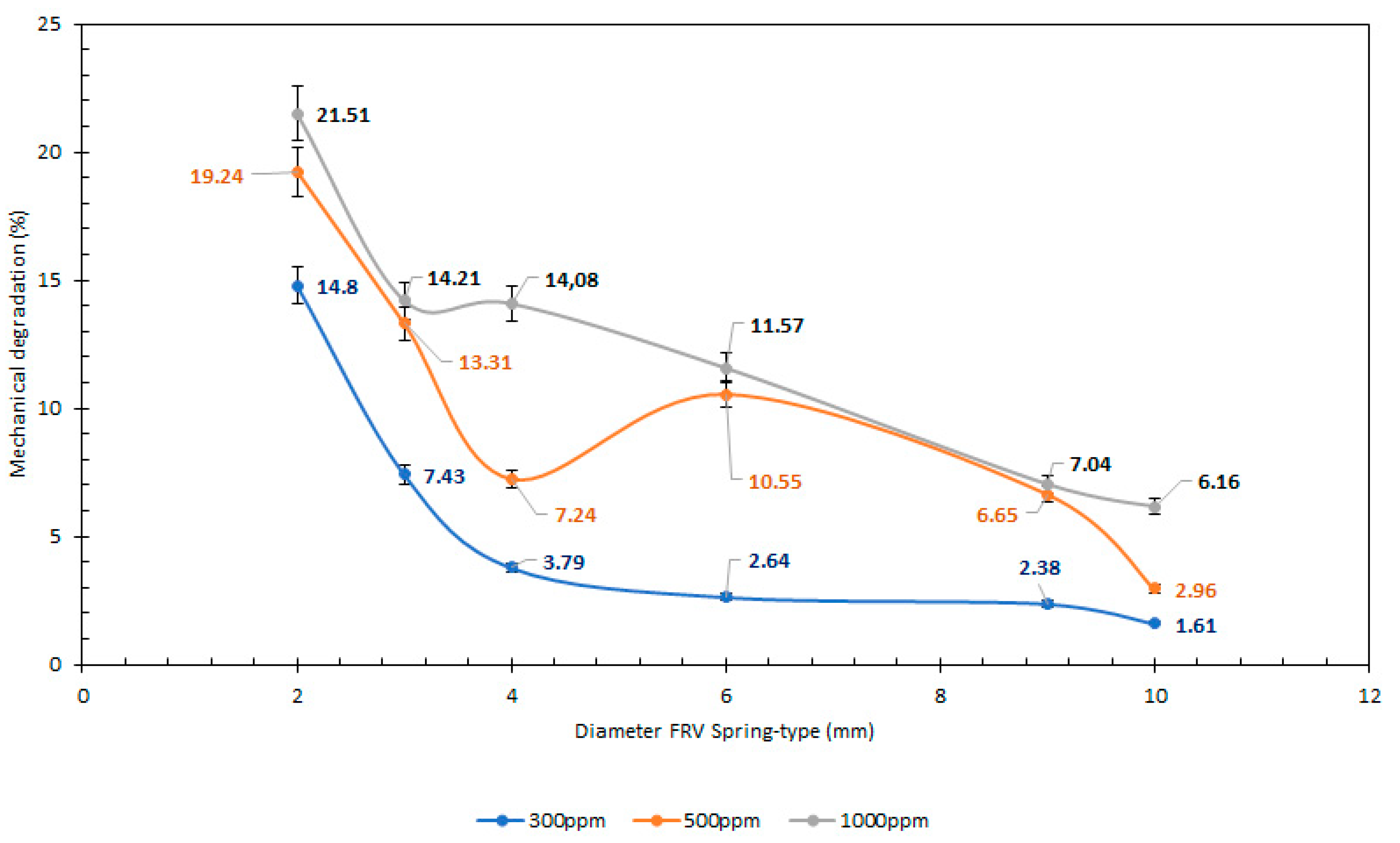
3.2.1. Determination of Mechanical Degradation
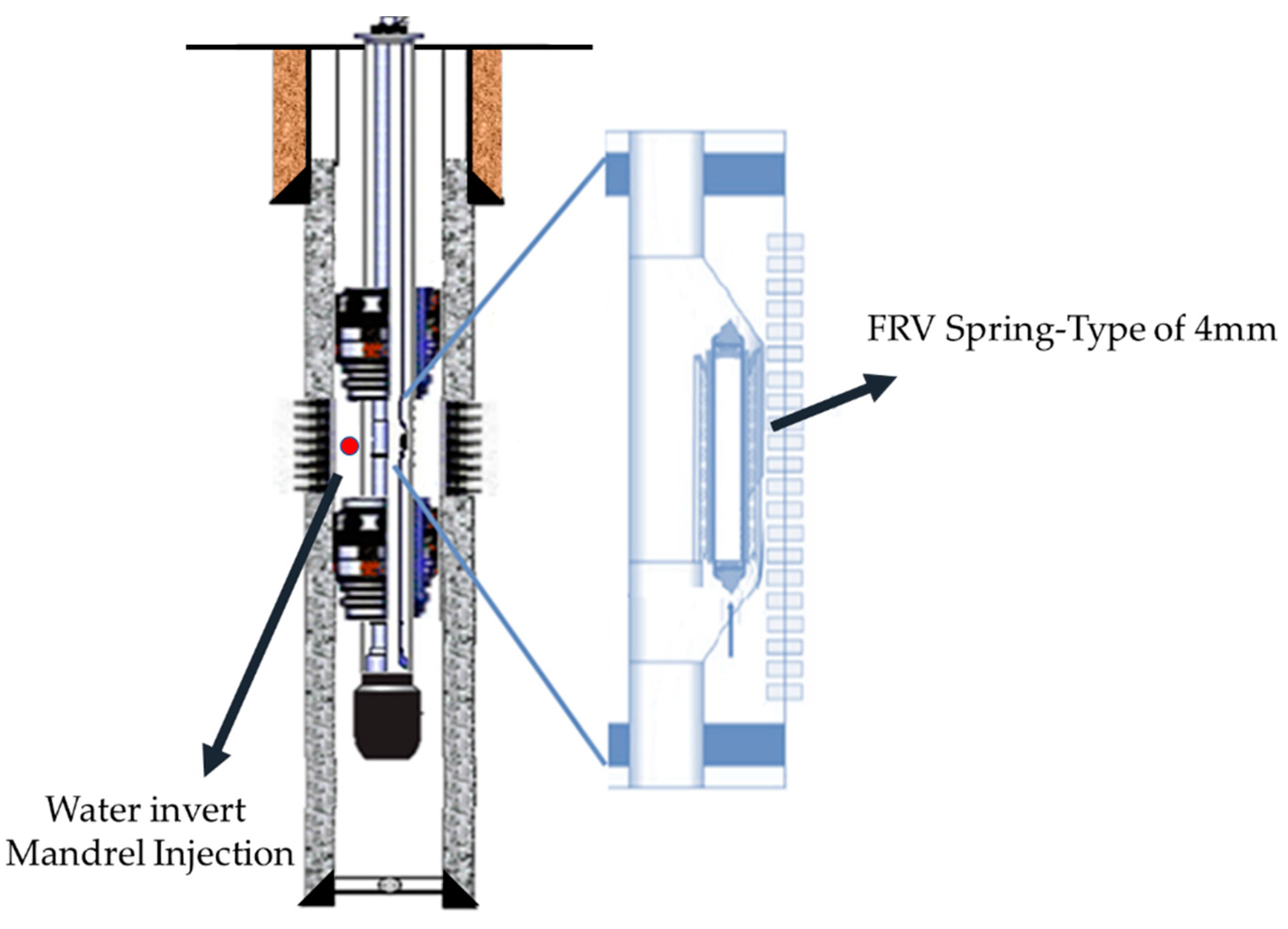
To improve the efficiency of vertical injection and the distribution of the injected fluid, it is necessary to propose the implementation of a selective injection process with flow regulators to improve the vertical efficiency in the reservoir by restricting the rate of water injected into each layer independently. For this, it is necessary to implement the following equipment in the mechanical state.

Mandrel

The mandrel selected to complete the well is with an internal pocket, to protect the flow regulating valve that is installed inside it. For the selection of this, it is necessary to consider that the dimensions must coincide with the diameter of the injection pipe; also, the technical specifications must support the pressure and flow rate conditions of the injection well. Additionally, a commercial high-pressure injection system design is used to improve the injection profile in a uniform way, in which the regulating valve is installed oppositely, filling it in the opposite direction to the flow. Therefore, it is recommended to use this type of technology which also reduces the degradation of the solution.

Flow Regulator Valve

It is recommended to complete the polymer injector with a minimum diameter for the FRV of a 4 mm spring-type valve, which was shown to be capable of reducing the degradation of the polymeric solution below 15%; in addition, this diameter regulating flow rates was proposed according to the technical specifications of the valve with a low flow spring.

3.3. Well Completion Proposal

Figure 11 and Table 5 show the recommended scheme of the polymer injector well, with the items explained above. The proposed completion corresponds only to selected sand for the polymer flooding process; however, it can be a duplicated mandrel and FRV in depth according to the number of reservoirs of interest. This well completion proposal applied only for the same pressure drop of the experimental study.
Is important to know that the proper completion of a well for polymer injection in the oil industry provides several significant advantages. In the first instance, there is improved oil recovery efficiency. This is due to the fact that polymers reduce water mobility in the reservoir, leading to a better oil sweep and an increased volume of oil recovered. On the other hand, there is increased reservoir life. By enhancing oil recovery efficiency, proper well completion extends the productive life of the reservoir, allowing for more oil extraction in a sustainable and cost-effective manner. In addition, there is viscosity reduction of the injection water. Polymers lower the viscosity of the injection water, facilitating its movement through the reservoir. This improves injection uniformity, water distribution, and sweep efficiency [44].
Another advantage of this completion is the reduced water consumption because polymer injection decreases water mobility, reducing the total amount of water required for oil recovery. This is particularly advantageous in water-scarce or expensive regions. As well, water mobility control by polymers helps to control the movement of water in the reservoir, preventing the bypassing of productive zones and improving sweep efficiency. Injection water is directed more effectively to areas with oil, maximizing recovery. Finally, there is a reduction of unwanted water production, because proper well completion with polymers helps minimize unwanted water production in producing wells. This reduces costs associated with handling and treating produced water.

3.4. Proposed Injection Parameters

Based on the results obtained and following the findings of Gheneim et al. (2017) [45], the following injection parameters are recommended:
Considering the interpretation of the experimental test results, it is advisable to use the lower values of flow velocity and critical deformation rate, which are 5.07 ft/s and 7713.34 s−1, respectively. These values correspond to the 300 ppm concentration, similar to what is injected in the pilot to ensure that degradation does not exceed 15%.
Taking these values as a reference and considering the daily injection volumes for each well, it is recommended to ensure that the deformation rate is not exceeded in each section of the solution flow line. This can be achieved by selecting the appropriate pipe diameter for each specific condition (Table 6).

3.5. The Application of the Regulating Valve in Unconventional Reservoir Polymer Injection Processes

Polymer injection is an advanced enhanced oil and gas recovery technique used to increase production in unconventional reservoirs [46]. These reservoirs, such as shale oil, shale gas formations, and tight oil, present significant challenges due to the low permeability of the rock, making it difficult to extract hydrocarbons [47]. Polymer injection is a strategy designed to address these challenges and improve recovery efficiency [48].
The completion control valve plays a crucial role in polymer injection in tight oil reservoirs, as it controls the flow and pressure of fluids injected into the reservoir. In this context, completion control valves are used to ensure efficient and safe polymer injection in this type of reservoir.
Similarly, completion control valves control the flow of fluids, including polymer solutions, being injected into the reservoir. This is essential to ensure that injection is at the right rate and pressure to maximize the efficiency of tight oil recovery.
Polymer injection in tight oil reservoirs aims to reduce water viscosity in the reservoir to improve the mobility of oil trapped in the rock [44]. This type of reservoir is characterized by: low permeability, high reservoir pressure, complex geology, viscous oil, and fractured reservoirs [49]. Regulating valves allow fine-tuning the flow of the polymer solution to achieve a homogeneous distribution in the reservoir, thus optimizing sweep efficiency and oil recovery [50,51].
In the same way, it is important to mention that in injection operations, it is essential to avoid problems such as well blockage or excessive water entry into the formation (coning). Regulating valves can help prevent these problems by controlling the flow of injection fluids and maintaining proper reservoir pressure. At the same time, safety in injection operations is paramount. Regulating valves must be reliable and capable of operating under adverse conditions, such as high pressures and temperatures, to ensure safe and efficient operation.

4. Conclusions

  • The flow rate of the polymer solution is directly proportional to its mechanical degradation. The stability of the polymer solution depends on the shear rate, type of polymer, water source, surface, and subsurface facilities through which the polymer circulates and the operative conditions of the injection process.
  • It is proposed to implement a selective injection polymer flooding process with flow regulators, which helps by restricting the rate of polymer injected into each layer independently and improving the vertical efficiency in the reservoir by using a configuration of inverted mandrels, which decreases the fluid velocity, improving the injection profile.
  • The flow regulator valve recommended is 4 mm to the injection flow required in the field of study. Pressure drop inter FRV and reservoir must be 100 psi or less; for higher drop pressure, the mechanical degradation will be higher.
  • It is recommended to evaluate in the laboratory and in the field other types of flow regulator valves and devices that have been designed in recent years, especially for polymer injection.
  • Completion control valves play an essential role in polymer injection in tight oil reservoirs. They enable precise control of the flow and pressure of injected fluids, which helps maximize sweep efficiency and oil recovery in low-permeability formations. They also ensure safe and reliable operation of injection operations, which is essential in the oil industry.

Author Contributions

Conceptualization, C.A.G.-M., M.Á.M.L., L.I.V.V., R.H.C., E.F.L., V.J.C.G., P.P.d.F. and S.C.-G.; Data curation, C.A.G.-M. and L.I.V.V.; Formal analysis, C.A.G.-M., M.Á.M.L. and L.I.V.V.; Funding acquisition, R.S.-S. and L.E.G.-M.; Investigation, C.A.G.-M. and L.I.V.V.; Methodology, C.A.G.-M. and M.Á.M.L.; Project administration, V.J.C.G., P.P.d.F., S.C.-G., L.E.G.-M. and R.H.C.; Resources, M.Á.M.L. and R.H.C.; Software, L.I.V.V., E.F.L. and S.C.-G.; Supervision, W.K.L.e.S. and R.S.-S.; Validation, E.F.L. and R.H.C.; Visualization, C.A.G.-M. and R.S.-S.; Writing—original draft, M.Á.M.L., L.I.V.V., W.K.L.e.S. and R.H.C.; Writing—review and editing, M.Á.M.L., L.I.V.V., E.F.L., V.J.C.G., R.H.C., P.P.d.F. and S.C.-G. All authors have read and agreed to the published version of the manuscript.

Funding

This research received no external funding.

Data Availability Statement

Data available on request.

Acknowledgments

The authors would like to acknowledge the institutional agreement 3009582 between Unviersidad de América (Fundación de América) - ECP (Ecopetrol S.A.) - ICP (Instituto Colombiano de Petróleo), for allowing the development of the project. The authors would like to acknowledge the Universidad de América for their technical support in this research thesis. Additionally, the authors thank Ecopetrol S.A., especially the Production Chemistry Laboratory, for making available the resources and equipment for the mechanical degradation tests. In memory of Marcos Lima Cardoso. Thank you for your joy, care, and teachings. Farewell, brother! The publication of this work was supported by PROPESP/UFPA (PAPQ).

Conflicts of Interest

The authors declare no conflict of interest.

References

  1. Lamas, L.F.; Botechia, V.E.; Schiozer, D.J.; Rocha, M.L.; Delshad, M. Application of polymer flooding in the revitalization of a mature heavy oil field. J. Pet. Sci. Eng. 2021, 204, 108695. [Google Scholar] [CrossRef]
  2. Manrique, E.; Thomas, C.; Ravikiran, R.; Izadi, M.; Lantz, M.; Romero, J.; Alvarado, V. EOR: Current status and opportunities. In SPE Improved Oil Recovery Conference? SPE: Richardson, TX, USA, 2010; p. SPE-130113. [Google Scholar]
  3. Gbadamosi, A.O.; Junin, R.; Manan, M.A.; Agi, A.; Yusuff, A.S. An overview of chemical enhanced oil recovery: Recent advances and prospects. Int. Nano Lett. 2019, 9, 171–202. [Google Scholar] [CrossRef]
  4. Rosa, A.J.; Carvalho, R.S.; Xavier, J.A.D. Engenharia de Reservatórios de Petróleo; Interciência: Caracas, Venezuela, 2006. [Google Scholar]
  5. Bai, Y.; Li, J.; Li, Q. Sensitivity analysis of the dimensionless parameters in scaling a polymer flooding reservoir. Transp. Porous Med. 2008, 73, 21. [Google Scholar] [CrossRef]
  6. Bello-Angulo, D.; Mantilla-Duarte, C.; Montes-Paez, E.; Guerrero-Martin, C. Box–Jenkins Methodology Application to Improve Crude Oil Production Forecasting: Case Study in a Colombian Field. Arab. J. Sci. Eng. 2021, 47, 11269–11278. [Google Scholar] [CrossRef]
  7. Castro, M.V. Escoamento de Polímeros em Meios Porosos. Ph.D. Thesis, Pontifícia Universidade Católica do Rio de Janeiro (PUC-RIO), Rio de Janeiro, Brazil, 2009. [Google Scholar]
  8. Firozjaii, A.M.; Saghafi, H.R. Review on chemical enhanced oil recovery using polymer flooding: Fundamentals, experimental and numerical simulation. Petroleum 2020, 6, 115–122. [Google Scholar] [CrossRef]
  9. Al-Anssari, S.; Ali, M.; Alajmi, M.; Akhondzadeh, H.; Khaksar Manshad, A.; Kalantariasl, A.; Iglauer, S.; Keshavarz, A. Synergistic effect of nanoparticles and polymers on the rheological properties of injection fluids: Implications for enhanced oil recovery. Energy Fuels 2021, 35, 6125–6135. [Google Scholar] [CrossRef]
  10. Bera, A.; Shah, S.; Shah, M.; Agarwal, J.; Vij, R.K. Mechanistic study on silica nanoparticles-assisted guar gum polymer flooding for enhanced oil recovery in sandstone reservoirs. Colloids Surf. A Physicochem. Eng. Asp. 2020, 598, 124833. [Google Scholar] [CrossRef]
  11. Guerrero-Martin, C.A.; Montes-Pinzon, D.; da Silva, M.M.M.; Montes-Paez, E.; Guerrero-Martin, L.E.; Salinas-Silva, R.; Camacho-Galindo, S.; Szklo, A. Asphaltene Precipitation/Deposition Estimation and Inhibition through Nanotechnology: A Comprehensive Review. Energies 2023, 16, 4859. [Google Scholar] [CrossRef]
  12. Uranta, K.G.; Rezaei Gomari, S.; Russell, P.; Hamad, F. Application of polymer integration technique for enhancing polyacrylamide (PAM) performance in high temperature and high salinity reservoirs. Heliyon 2019, 5, e02113. [Google Scholar] [CrossRef]
  13. Afolabi, F.; Mahmood, S.M.; Yekeen, N.; Akbari, S.; Sharifigaliuk, H. Polymeric surfactants for enhanced oil recovery: A review of recent progress. J. Pet. Sci. Eng. 2022, 208, 109358. [Google Scholar] [CrossRef]
  14. Sun, F.; Lin, M.; Dong, Z.; Zhang, G. Delayed-crosslink hydrogel for improving oil recovery in differential heterogeneous reservoirs. ACS Omega 2019, 5, 228–235. [Google Scholar] [CrossRef]
  15. Taber, J.J.; Martin, F.D. Technical screening guides for enhanced oil recovery. In Proceedings of the 58th Annual Technical Conference and Exhibition, San Francisco, CA, USA, 5–8 October 1983. [Google Scholar]
  16. Muhammed, N.S.; Haq, M.B.; Al-Shehri, D.; Rahaman, M.M.; Keshavarz, A.; Hossain, S.Z. Comparative study of green and synthetic polymers for enhanced oil recovery. Polymers 2020, 12, 2429. [Google Scholar] [CrossRef]
  17. Ferreira, M.Z. Injeção Contínua e Alternada de Água e de Polímeros para a recu-Peração de Petróleo. Master’s Thesis, Universidade Estadual de Campinas, Campinas, São Paulo, Brazil, 2012. [Google Scholar]
  18. Zhong, H.; He, Y.; Yang, E.; Bi, Y.; Yang, T. Modeling of microflow during viscoelastic polymer flooding in heterogenous reservoirs of Daqing Oilfield. J. Pet. Sci. Eng. 2022, 210, 110091. [Google Scholar] [CrossRef]
  19. Rosenkilde, C.; Brakstad, K.; Smith, J.B. Degradation of synthetic polymers during radial injection in a sandstone. In Proceedings of the 78th EAGE Conference and Exhibition 2016: Efficient Use of Technology—Unlocking Potential, Vienna, Austria, 29–30 May 2016. [Google Scholar] [CrossRef]
  20. Li, X.; Zhang, F.; Liu, G. Review on polymer flooding technology. In IOP Conference Series: Earth and Environmental Science; IOP Publishing: Bristol, UK, 2021; Volume 675, p. 012199. [Google Scholar]
  21. Daza, J.; Castro, R. Evaluación Técnico-Financiera de los Pilotos IOR/EOR Ejecutados en Colombia con Tecnología de Inyección de Polímero HPAM; Acipet: Cartagena, Colombia, 2022. [Google Scholar]
  22. Lake, L. Polymer Methods. In Enhanced Oil Recovery; Prentice Hall Inc.: Upper Saddle River, NJ, USA, 1989; pp. 314–353. Available online: https://biblos.uamerica.edu.co/cgi-bin/koha/opac-detail.pl?biblionumber=29170 (accessed on 10 June 2023).
  23. Davarpanah, A. Parametric study of polymer-nanoparticles-assisted injectivity performance for axisymmetric two-phase flow in EOR processes. Nanomaterials 2020, 10, 1818. [Google Scholar] [CrossRef]
  24. Liu, J.; Jiang, L.; Liu, T.; Yang, D. Modeling tracer flowback behaviour for a multifractured horizontal well in a tight oil reservoir using the embedded discrete fracture model. J. Pet. Sci. Eng. 2022, 212, 110347. [Google Scholar] [CrossRef]
  25. Buitrago-Rincon, D.L.; Sadtler, V.; Mercado, R.A.; Roques-Carmes, T.; Marchal, P.; Muñoz-Navarro, S.F.; Sandoval, M.; Pedraza-Avella, J.A.; Lemaitre, C. Silica Nanoparticles in Xanthan Gum Solutions: Oil Recovery Efficiency in Core Flooding Tests. Nanomaterials 2023, 13, 925. [Google Scholar] [CrossRef]
  26. Sorbie, K. Polymer stability. In Polymer-Improved Oil Recovery; Springer: Berlin/Heidelberg, Germany, 1991; pp. 83–125. [Google Scholar] [CrossRef]
  27. Poveda, I.D.; Guerrero-Martin, C.A.; Espinosa, C.; Castro, R.H. Simulación Numérica Estocástica de Tratamientos de Conformance Profundo Usando Polímero de Activación Térmica. 2023. Available online: https://revistas.uis.edu.co/index.php/revistafuentes/article/view/14379 (accessed on 2 June 2023).
  28. Weisman, I.; Thomann, M.; Gamboa, M.; Godino, G.; Gandi, S. Polymer Flooding from Day One: Reservoir Modelling Challenges and Development Strategy Definition. In SPE Latin America and Caribbean Petroleum Engineering Conference; SPE: Richardson, TX, USA, 2023; p. D021S012R001. [Google Scholar]
  29. Shiran, B.S.; Skauge, A. Enhanced oil recovery (EOR) by combined low salinity water/polymer flooding. Energy Fuels 2013, 27, 1223–1235. [Google Scholar] [CrossRef]
  30. Pogaku, R.; Fuat, N.H.M.; Sakar, S.; Cha, Z.W.; Musa, N.; Tajudin, D.N.A.A.; Morris, L.O. Polymer flooding and its combinations with other chemical injection methods in enhanced oil recovery. Polym. Bull. 2018, 75, 1753–1774. [Google Scholar] [CrossRef]
  31. Ding, L.; Wu, Q.; Zhang, L.; Guérillot, D. Application of fractional flow theory for analytical modeling of surfactant flooding, polymer flooding, and surfactant/polymer flooding for chemical enhanced oil recovery. Water 2020, 12, 2195. [Google Scholar] [CrossRef]
  32. Jouenne, S.; Chakibi, H.; Levitt, D. Polymer stability after successive mechanical-degradation events. SPE J. 2018, 23, 18–33. [Google Scholar] [CrossRef]
  33. Corredor, L.M.; Husein, M.M.; Maini, B.B. A review of polymer nanohybrids for oil recovery. Adv. Colloid Interface Sci. 2019, 272, 102018. [Google Scholar] [CrossRef]
  34. Morel, D.C.; Vert, M.; Jouenne, S.; Gauchet, R.; Bouger, Y. First polymer injection in deep offshore field Angola: Recent advances in the Dalia/Camelia field case. Oil Gas Facil. 2012, 1, 43–52. [Google Scholar] [CrossRef]
  35. Saboorian-Jooybari, H.; Dejam, M.; Chen, Z. Heavy oil polymer flooding from laboratory core floods to pilot tests and field applications: Half-century studies. J. Pet. Sci. Eng. 2016, 142, 85–100. [Google Scholar] [CrossRef]
  36. Sheng, J.J. Polymer Viscoelastic Behavior and Its Effect on Field Facilities and Operations. In Modern Chemical Enhanced Oil Recovery: Theory and Practice; Gulf Professional Publishing: Oxford, UK, 2011; pp. 207–238. [Google Scholar] [CrossRef]
  37. Jouenne, S.; Anfray, J.; Cordelier, P.R.; Mateen, K.; Levitt, D.; Souilem, I.; Marchal, P.; Lemaitre, C.; Choplin, L.; Nesvik, J.; et al. Degradation (or Lack Thereof) and Drag Reduction of HPAM Solutions During Transport in Turbulent Flow in Pipelines. Oil Gas Facil. 2015, 4, 80–92. [Google Scholar] [CrossRef]
  38. Herrera, J.J.; Prada, L.C.; Maya, G.A.; Gomez-Vergel, J.L.; Castro, R.H.; Quintero, H.I.; Diaz, R.; Perez, E.E. CFD simulation of HPAM EOR solutions mechanical degradation by restrictions in turbulent flow. CTF Cienc. Tecnol. Futuro 2020, 10, 115–129. [Google Scholar] [CrossRef]
  39. Vanegas, P.A.V.; Ruiz, T.Y.Z.; Macualo, F.H.E.; Martin, C.A.G. Metodología para la formulación de proyectos de recuperación química mediante analogías. Rev. Fuentes Reventón Energético 2019, 17, 29–35. [Google Scholar]
  40. Lu, X.G.; Sun, S.Q.; Shan, G.J.; Lin, L.H. Improved Waterflood Recovery for a Mature Oilfield with Challenging Reservoir Conditions and Complex Development Status. In Abu Dhabi International Petroleum Exhibition and Conference 2023; SPE: Richardson, TX, USA, 2023; p. D021S033R006. [Google Scholar]
  41. API Production Department. Recommended Practices for Evaluation of Polymers Used in Enhanced Oil Recovery Operations, 1st ed.; American Petroleum Institute: Washington, DC, USA, 1990. [Google Scholar]
  42. Herrera, J.J.; Pérez, E.E.; Prada, L.C.; Quintero, H.I.; Gutierrez, M.; Maya, G.A.; Maldonado, L.Y.; Castro, R. Análisis, diseño e implementación de válvulas reguladoras de flujo-VRF para yacimientos multicapas sometidos a procesos de recuperación química de petróleo. In Proceedings of the Congreso Colombiano de Petróleo y Gas Natural, Cartagena, Colombia, 16–18 August 2022; Acipet: Bogota, Colombia, 2022. [Google Scholar]
  43. Solórzano, P.; Ahmedt, D.; Jaimes, C.; Henao, W.; Vega, S.; Guerrero, C.; Meza, E.; León, J.; Dueñas, D. Selectivizing a Singled Bed Reservoir, A Successfully Application to Increase the Vertical Displacement Efficiency in a Heavy Oil Waterflooding Project. In Proceedings of the SPE Trinidad and Tobago Section Energy Resources Conference, Port of Spain, Trinidad and Tobago, 25–27 June 2018; OnePetro: Richardson, TX, USA, 2018. [Google Scholar]
  44. Julia, H.; Prada, L.; Henderson, Q.; Gustavo, M.; Laura, M.; José, G.-V.; Mauricio, G.; Rubén, C.; Pérez, E. Fluid dynamics simulations of pressure and flow control devices in polymer flooding selective use in enhanced oil recovery. Geoenergy Sci. Eng. 2023, 227, 211907. [Google Scholar] [CrossRef]
  45. Gheneim, T.; Azancot, A.; Acosta, T.; Zapata, J.F.; Chaparro, C.; Lobo, A.; Jimenez, A.M.; Perez, G. Enhanced Oil Recovery in a High Stratigraphic Complex Reservoir: Casabe Project Case Study. In Abu Dhabi International Petroleum Exhibition and Conference; SPE: Richardson, TX, USA, 2017; p. D041S115R002. [Google Scholar]
  46. Syed, F.I.; Dahaghi, A.K.; Muther, T. Laboratory to field scale assessment for EOR applicability in tight oil reservoirs. Pet. Sci. 2022, 19, 2131–2149. [Google Scholar] [CrossRef]
  47. Al-Hajri, S.; Mahmood, S.M.; Abdulelah, H.; Akbari, S. An overview on polymer retention in porous media. Energies 2018, 11, 2751. [Google Scholar] [CrossRef]
  48. Zhong, H.; Zhang, W.; Fu, J.; Lu, J.; Yin, H. The performance of polymer flooding in heterogeneous type II reservoirs—An experimental and field investigation. Energies 2017, 10, 454. [Google Scholar] [CrossRef]
  49. Zhou, N.; Lu, S.; Wang, M.; Huang, W.; Xiao, D.; Jiao, C.; Wang, J.; Tian, W.; Zhou, L.; Chen, F.; et al. Limits and grading evaluation criteria of tight oil reservoirs in typical continental basins of China. Pet. Explor. Dev. 2021, 48, 1089–1100. [Google Scholar] [CrossRef]
  50. Alhotan, M.M.; Fernandes, B.R.B.; Delshad, M.; Sepehrnoori, K. A Systemic Comparison of Physical Models for Simulating Surfactant–Polymer Flooding. Energies 2023, 16, 5702. [Google Scholar] [CrossRef]
  51. Fani, M.; Pourafshary, P.; Mostaghimi, P.; Mosavat, N. Application of microfluidics in chemical enhanced oil recovery: A review. Fuel 2022, 315, 123225. [Google Scholar] [CrossRef]
Figure 1. Experimental setup for the evaluation of mechanical degradation on a laboratory scale [42].
Energies 16 07565 g001
Figure 2. Stock solution at 5000 ppm.
Energies 16 07565 g002
Figure 3. Percentage of mechanical degradation vs. diameter of the spring-type VRF for a 300 ppm solution under laboratory conditions.
Energies 16 07565 g003
Figure 4. Variation in viscosity vs. diameter of spring-type VRF for a 300 ppm solution under laboratory conditions.
Energies 16 07565 g004
Figure 5. Percentage of mechanical degradation vs. diameter of the spring-type VRF for a 500 ppm solution under laboratory conditions.
Energies 16 07565 g005
Figure 6. Variation in viscosity vs. diameter of spring-type VRF for a 500 ppm solution under laboratory conditions.
Energies 16 07565 g006
Figure 7. Percentage of mechanical degradation vs. diameter of the spring-type VRF for a 1000 ppm solution under laboratory conditions.
Energies 16 07565 g007
Figure 8. Variation in viscosity vs. diameter of spring-type VRF for a 1000 ppm solution under laboratory conditions.
Energies 16 07565 g008
Figure 9. (a). Percentage mechanical degradation vs. shear rate in spring-type VRF for a 300 ppm solution under laboratory conditions. (b) Percentage mechanical degradation vs. shear rate in spring-type VRF for a 500 ppm solution under laboratory conditions. (c) Percentage mechanical degradation vs. shear rate in spring-type VRF for a 1000 ppm solution under laboratory conditions.
Energies 16 07565 g009aEnergies 16 07565 g009b
Figure 10. Mechanical degradation vs. diameter of FRV for solutions of 300, 500, and 1000 ppm.
Energies 16 07565 g010
Figure 11. Well completion proposal.
Energies 16 07565 g011
Table 1. Parameters influencing mechanical degradation.
Elements of Polymer
Injection
Parameters Influencing
Mechanical Degradation
Relationship with DegradationModifiable/
Not Modifiable
Polymer solution
(Sheng, 2011) [36],
(K. S. Sorbie, 1991) [26]
Polymer type (synthesis)The degree of resistance to shear rate depends on this.Not modifiable
Critical shear rateIt is associated with the type of polymer and its own design.Not modifiable
Polymer concentrationIt presents a behavior directly proportional to the degradation.Modifiable
Flow lines and mechanical
condition (Jouenne et al., 2018) [32]
Pipe diametersIt is directly proportional to the critical velocity and inversely proportional to the degradation.Not modifiable
Pressure drops
(accessories)
They generate a sudden increase in the flow velocity of the polymer, so they will be considered as critical points.Modifiable, main
parameter of
evaluation in the FRV
Injection process
(Jouenne et al., 2015) [37]
Flow ratesDirectly proportional to pressure drops and polymer degradation.Not modifiable
Injection temperatureIt does not represent a significant mechanical degradation factor.Not modifiable
Source: The author.
Table 2. Tabulation of laboratory-scale experimental results of the evaluation of the spring-type valve.
Concentration (ppm)Diameters (mm)Initial Viscosity (Cp)Final Viscosity (Cp)Deg
(%)
300215.613.414.8
315.5514.457.43
415.2514.73.79
615.915.52.64
913.3513.052.38
10 (full open)13.1512.951.61
500228.823.419.24
330.826.813.31
42725.17.24
630.627.4510.55
927.8266.65
10 (full open)26.725.16.16
1000283.565.721.51
385.973.814.21
484.973.0514.08
685.4575.6511.57
981.7767.04
10 (full open)78.576.22.96
Table 3. Average Inlet Viscosity vs Average Mechanical Degradation.
Average Inlet Viscosity (cP)Average Shear Viscosity (cP)Average Overall Viscosity Loss (%)Average Mechanical Degradation Number of Tests
300 ppm12
2 mm2
15.613.414.10%15.07%2
3 mm2
15.5514.457.06%7.54%2
4 mm2
15.2514.73.59%3.84%2
6 mm2
15.915.52.52%2.68%2
9 mm2
13.3513.052.22%2.40%2
10 mm full open2
13.1512.951.52%1.65%2
500 ppm11
2 mm1
28.823.418.75%19.42%1
3 mm2
30.826.813.00%13.44%2
4 mm2
29.828.73.69%3.81%2
6 mm2
30.627.4510.21%10.55%2
9 mm2
27.7526.93.06%3.17%2
10 mm full open2
26.3525.91.65%1.71%2
1000 ppm12
2 mm2
83.565.721.32%21.58%2
3 mm2
85.973.814.09%14.25%2
4 mm2
84.973.0513.95%14.12%2
6 mm2
85.4575.6511.46%11.59%2
9 mm2
79.778.850.91%0.92–4.13%2
10 mm full open2
78.2577.351.14%1.16%2
Table 4. Optimal injection diameters of a polymer solution of 500 ppm for a spring-type FRV.
Diameter of the FRV (mm)Deg (%)
Laboratory
Shear Rate
Evaluated
(s−1)
Regulated Flow
Spring Low Flow
(+/−10%) (BPD)
Regulated Flow
Spring High Flow
(+/−10%) (BPD)
219.24%702,87857138
313.31%208,260151258
47.24%87,859245421
610.55%26,0336161170
96.65%771310631918
106.16%5623No Reg.No Reg.
Table 5. Proposed wellbore mechanical condition.
I
T
EM
O.D (IN)I.D (IN)Length (Ft)Depth from (ft)Depth to (ft)QuantityDescription
102.8752.4413110.32-3093.90136Tubing Joint 2-7/8″ Pin × Box 22 Ft
92.8752.4416.13093.903100.00 Pup Joint 2-7/8″ Pin × Box × 6 ft.
2 Rubber Top
86.0632.43803100.003100.001Hydraulic Packer 7″ × 2-7/8”
2 Rubbers Down
72.8752.44130.533100.003130.531Tubing Joint 2-7/8″ Pin × Box 30 Ft
65.1872.4418.823130.533139.351Water Mandril Injection 2-7/8”
52.8752.44191.483139.353230.834Tubing Joint 2-7/8″ Pin × Box 22 Ft
2 Rubber Top
46.0632.43803230.833230.831Hydraulic Packer 7″ × 2-7/8”
2 Rubbers Down
32.8752.44122.873230.833253.701Tubing Joint 2-7/8″ Pin × Box 22 Ft
22.8752.44122.873253.703276.5712 7/8″ Wireline Entry Guide Shoe
12.8752.44122.873276.573299.4412 7/8” Blind Nipple
Table 6. Recommended injection parameters.
Injection ParameterValueUnit
Maximum pressure2000Psi
Solution concentration320Ppm
Maximum injection capacity3000STBPD
Maximum average injection flow rate per well300STBPD
Disclaimer/Publisher’s Note: The statements, opinions and data contained in all publications are solely those of the individual author(s) and contributor(s) and not of MDPI and/or the editor(s). MDPI and/or the editor(s) disclaim responsibility for any injury to people or property resulting from any ideas, methods, instructions or products referred to in the content.

