Abstract
In order to address the issue of battery cell disparity in lithium-ion battery systems, battery balancing techniques are required. This paper proposes an improved battery balancing strategy within a reconfigurable converter system. The strategy is based on the state of charge (SOC) of batteries, and utilizes the reconfigurable converter system to transfer energy from battery modules with high SOC to those with lower SOC. Additionally, it allows for battery module balancing while supplying power to loads. A MATLAB/Simulink simulation model with five batteries was built to validate the effectiveness of the proposed balancing strategy under unloaded and loaded conditions. The simulation results demonstrate that the proposed strategy achieves more efficient and accurate battery module balancing compared to the previous balancing modes.
1. Introduction
Due to the cell-to-cell variation in lithium-ion battery systems, individual cells may become overcharged or over-discharged during charging and discharging processes. Failure to perform timely and effective balancing may result in decreased battery pack lifespan, reduced capacity, performance degradation, and even safety hazards such as fire [1,2]. Therefore, battery balancing plays an important role in improving overall battery pack lifespan, ensuring battery safety and reliability, and increasing energy utilization efficiency [3,4].
Battery balancing methods can be classified into passive balancing and active balancing, depending on whether energy dissipation is involved [5].
Passive balancing is mainly achieved by using resistors to discharge high-energy battery cells, consuming their excess energy in the form of heat to achieve energy consistency among all cells. The advantages of passive balancing include simple and feasible circuit structure, low cost, small circuit volume, and easy control. However, since energy is dissipated in the form of heat, the overall energy utilization efficiency of the battery module is relatively low [6,7].
Active balancing mainly utilizes energy storage components such as capacitors and inductors to transfer energy between cells, which can be achieved with different circuit structures. Active balancing has high energy utilization efficiency, high balancing efficiency, and fast balancing speed. However, it usually comes with complex circuit structures and control strategies, resulting in higher implementation costs [8].
Balancing circuits typically use battery voltage or state of charge (SOC) as the balancing indicators. When using battery voltage as the balancing indicator, the advantage lies in its simplicity and ease of implementation. However, the disparate internal resistance of batteries can lead to suboptimal balancing effects. On the other hand, using SOC as the balancing indicator offers the advantage of superior balancing effectiveness, but it entails complex calculations and greater implementation difficulties.
Many researchers have conducted research on battery balance using battery voltage as the balancing indicator. For example, K. Nishijima et al., 2000.proposed a PWM-controlled DC-DC converter technique that utilized battery voltage as the balancing indicator, which was comparatively simple and efficient [9]. Siqi Li et al.,2012. designed a balancing circuit composed of Metal-Oxide-Semiconductor Field-Effect Transistors (MOSFETs) and a multi-winding transformer. It achieved energy transfer from batteries with higher voltages to those with lower voltages by controlling the turning on and off of the MOSFETs [10].
As technology progresses, battery balancing methods based on SOC as the balancing indicator have gradually become mainstream. Cao et al., 2020 studied a hierarchical SOC balancing control method for battery energy storage systems, which achieved SOC balancing between battery cells and modules. This was accomplished through modulation of the duty cycle proposed for power converter switches [11]. Wang et al., 2022 proposed a layered Model Predictive Control (MPC)-based balancing approach utilizing adaptive estimation. Different balancing topologies were explored, and Hardware-in-the-Loop (HIL) testing was conducted to verify the real-time feasibility of the proposed MPC balancing strategy. Finally, the impact of series-connected battery cell count and the adopted topology on balancing performance were discussed [12]. The balancing scheme proposed by Yun et al. uses SOC as the balancing variable and a closed-loop flyback converter as the energy transfer circuit, which can effectively solve the inconsistency of battery energy [13]. Li et al. proposed a two-layer equalization method using SOC as the equalization index, combining the reconfigurable topology with the converter active equalization method. A simulation circuit of was built consisting of 12 battery cells in MATLAB/Simulink to verify its equalization effect [14]. The MATLAB version used in this paper is version 2022b.
Currently, reconfigurable battery energy storage systems have attracted increasing attention due to their ability to dynamically reconfigure the battery topology in real time to adapt to specific application requirements [15,16,17,18,19]. This can more effectively utilize battery resources, isolate corresponding batteries according to their current state of charge and health status without affecting the charge and discharge processes of other batteries, and extend the battery’s service life while reducing the possibility of module failure [20,21].
The state of charge (SOC) is commonly used to characterize the amount of charge in a battery cell. A battery cell’s SOC is defined by the ratio of the cell’s present amount of charge to its rated charge capacity [22]. There is relatively little research on the combination of reconfigurable and integrated converters for battery systems. In [23], the authors proposed an integrated reconfigurable converter structure that can be used for high-voltage battery systems. In [24,25], the authors proposed load-sharing balancing strategies and distributed balancing control for battery modules based on the circuit structure of the integrated reconfigurable converter. In [26], the authors improved the structure of the integrated reconfigurable converter system and proposed a new balancing strategy. However, this balancing strategy failed to achieve free energy exchange between battery modules and only demonstrated effective balancing when the SOC of batteries followed a strict hierarchical order.
In this paper, we improve on the battery balancing strategy proposed in [26] and conduct a comparative analysis. Due to only discussing the balancing strategy, the structure of the reconfigurable converter is simplified. During the balancing process, this balancing strategy is capable of transferring energy from the battery module with the highest SOC to the one with the lowest SOC. Only the battery modules with the highest and lowest SOC are involved in the balancing process, while other battery modules remain unaffected. This approach effectively avoids repetitive charge–discharge cycles in certain batteries during balancing. As a result, it enhances system stability and prolongs battery lifespan.
This paper is organized as follows: Section 2 introduces the integrated system of reconfigurable battery and converter and illustrates its working principle. Section 3 describes the balancing strategy and design of the control system. Section 4 presents simulation experimental results and analysis. Section 5 discusses the experimental results and equilibrium strategies. Section 6 concludes this paper.
2. Structure and Working Principle of Integrated Reconfigurable Converter
The integrated reconfigurable converter is shown in Figure 1. In the figure, S1–S10 and Sb are IGBT, and D1 and D2 are diodes. L is the inductance, C is the capacitance. B1–B3 are batteries. For simplicity and convenience, three battery modules are used as examples for illustration. However, the same configuration can be applied to systems with a higher number of battery modules. The system consists of a battery module selector and boost converters. The boost converter’s configuration is displayed in Figure 2. The battery modules can be dynamically reconfigured to select different input voltages. Table 1 shows the different battery modules that the battery module selector can choose from. When the input voltage changes, the range of output voltage that the boost converter can provide also changes accordingly. The relationship between the output voltage Vout, input voltage Vin, and the duty cycle D of the boost converter is expressed in Equation (1).
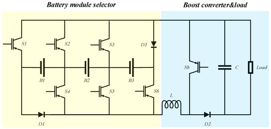
Figure 1.
Integrated reconfigurable converter structure.
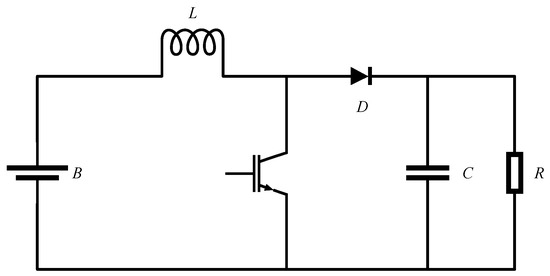
Figure 2.
Boost converter.

Table 1.
Different input modes of battery modules.
The Battery Management System (BMS) can identify battery modules with relatively high States of Charge (SOC), and the battery module selector prioritizes their discharging by switching corresponding switches. The BMS can dynamically reconfigure battery modules to have two different working modes: power supply mode and balancing mode. These two modes will be elaborated on in detail below.
2.1. Power Supply Mode
Figure 3a,b illustrate the configuration of the battery system when they are powering the load. In this mode, the converter operates in boost mode, and the control system can select different battery modules through the battery module selector to discharge at different input voltages. In the case of a failure among switches S1–S6, a flow path is required to release the energy from the inductor to protect the circuit from damage. Figure 4 shows the path along which the inductor current flows. This path can also be used to return the energy from the inductor back to all battery modules, which not only protects the circuit, but also avoids wasting energy.

Figure 3.
Battery system power supply mode: (a) B1 provides power to the load, (b) B2 and B3 provide power to the load.
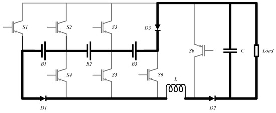
Figure 4.
The freewheeling path for the inductor current.
2.2. Balance Mode
The balancing mode enables energy transfer from battery modules with high SOC to those with lower SOC, and this energy transfer is achieved by utilizing the inductor L. Figure 5a–c demonstrate the leftward energy transfer. Figure 5a shows the energy transfer between one module and another. In this figure, switches Sb and S3 are always on, and by turning on switch S6 and turning off switch S4, the energy in B3 shifts to inductor L. Then, by turning off switch S6 and turning on switch S4, the energy in inductor L is released and charges B2, achieving energy transfer from B3 to B2. The same switching cycle is repeated until the two modules reach equilibrium. Figure 5b illustrates the energy transfer from one module to two modules, and Figure 5c shows the energy transfer from two modules to one module.
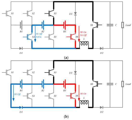
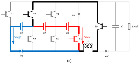
Figure 5.
Illustration of balancing mode during one switching cycle. (a) Module to a module (B3 is discharged into B2). (b) Module to modules (B3 is discharged into B1 and B2). (c) Modules to a module (B2 and B3 are discharged into B1).
3. Balancing Strategy and Control System Design
This section describes the system balancing strategy and the design of the control system.
3.1. Balancing Strategy
The proposed new balancing strategy first identifies the battery module with the highest SOC and charges the inductor. Since the current flowing through the inductor cannot change immediately, the energy on the inductor is transferred to the battery module with the lowest SOC by changing the switch status. This balancing strategy can accelerate the balancing speed and can also be applied when batteries are powering the load. The specific balancing strategies for scenarios with and without load usage are explained below:
When there is no load usage, the balancing measure of the battery system is to have the battery module with the highest SOC store energy in the inductor, and then change the switch status to release the energy stored on the inductor to the battery module with the lowest SOC. As shown in Figure 6a,b, when battery module B3 has the highest charge, while B2 has the lowest, the balancing strategy adjusts such that battery module B3 first charges the inductor through switches S3 and S6, then maintains the closure of switch S3, and turns S4 On and S6 Off to transfer the energy from the inductor to B2. Figure 6b shows the energy transfer from battery module B3 to battery module B1 when B3 has the highest charge while B1 has the lowest.
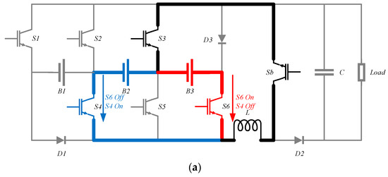
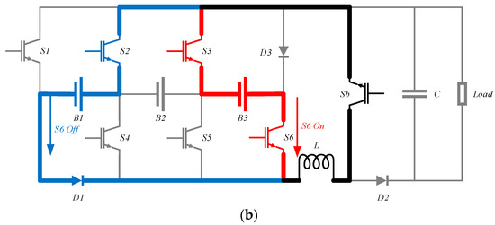
Figure 6.
Balancing strategy when not using load: (a) B3 is discharged into B2. (b) B3 is discharged into B1.
When the load needs to be used, the converter is connected, and the balancing strategy of the battery system is adjusted so that the battery module with the highest charge level supplies power to both the load and the inductor, then, by changing the switch status, the energy stored on the inductor is released to the battery module with the lowest SOC. As shown in Figure 7a,b, when battery module B1 has the highest charge level while B2 has the lowest, with the load operating, the balancing strategy adjusts such that battery module B1 supplies power to the inductor and the load via switches S1 and S4, then maintains the closure of switch S4, and turns switch S3 On and S1 Off to transfer the energy from the inductor to the load and B2. Figure 7b shows the case when battery module B1 has the highest charge level while B3 has the lowest.
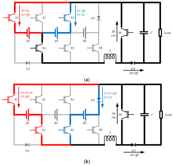
Figure 7.
Balancing strategy when using load: (a) B1 is discharged into B2. (b) B1 is discharged into B3.
Figure 8 illustrates the flow diagram of the balancing system: First, all SOC values of battery modules are obtained and sorted to find the module with the highest and lowest SOC levels. If the difference in SOC between two modules exceeds the threshold value ∆e, the control system controls the corresponding switches of these two modules to transfer excess charge from the highest SOC module to the lowest SOC module. If there is no load during the balancing process, switch Sb remains closed. If the load is used, a PWM signal is used to control the On/Off state of switch Sb to connect the converter, ensuring that a single battery module can provide the required voltage. When the SOC difference between any two modules is lower than the threshold value ∆e, the balancing process ends, and the required battery modules can be connected according to Table 1 to change the working voltage range of the boost converter. Once the SOC difference exceeds the threshold value ∆e, the balancing procedure starts over. This iterative process ensures effective SOC balancing and prevents overcharging or over-discharging, thus improving the overall life and safety performance of the battery.
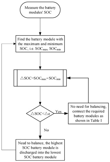
Figure 8.
Flow diagram of the balancing management system.
3.2. Control System Design
This section describes the design of a balancing system with and without load, and the balancing system controllers are both PI controlled.
3.2.1. Controller Design for the Balancing Operation When No Load Is Used
The system diagram of the PI controller without load balancing mode is shown in Figure 9. In order to design the PI controller, the small-signal modeling shown in Figure 10 is first derived.

Figure 9.
Controller design for the balancing operation when no load is used.
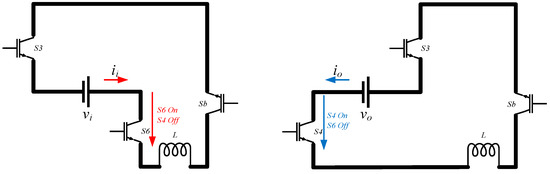
Figure 10.
Simplified topology of the balancing mode without load usage in small-signal modeling.
The average state equation for balancing mode without load usage is as follows:
Introducing AC perturbations into the above equation yields
The small-signal model can then be written as
The above equation can be obtained by applying Laplace transform as follows:
The transfer function of the balancing mode without load usage can be obtained from Equation (5):
The transfer function of the PWM modulator can be modeled as follows:
where is the peak value of the sawtooth carrier signal. Using the small-signal transfer function (6), the PI controller parameters Kp and Ki were calculated to regulate the current on the inductor, namely the balancing current, for achieving the desired open-loop phase margin at the required cutoff frequency. The Bode plot of the control loop in the charging mode is shown in Figure 11a. From the Bode plot, it can be inferred that the system is stable, as the open-loop phase margin (PM) at the cutoff frequency is greater than zero.
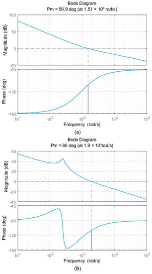

Figure 11.
Bode diagrams of (a) balance mode control circuit when not using load, (b) internal current control circuit when using load, (c) external voltage control circuit when using load.
3.2.2. Controller Design for the Balancing Operation When Load Is Used
In the balancing mode when load is used, the double-loop control system is adopted for regulating the Buck–Boost circuit composed of the battery pack, inductor, and diode D2, as shown in Figure 12. The inner loop is a high-bandwidth current control loop, while the outer loop is a voltage control loop with lower bandwidth and slower response compared to the inner loop. The voltage of the outer loop adjusts the output voltage by providing a reference current signal to the current inner loop, which regulates the current on the inductor. Owing to the faster response of the inner loop, the outer loop can be treated separately in the circuit design process, in order to simplify the controller design.
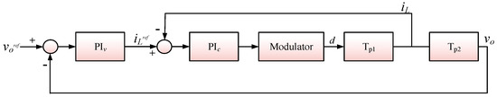
Figure 12.
Controller design for the balancing operation when load is used.
- Design of internal current control loop: In order to design the PI controller, the small-signal modeling as shown in Figure 13 is first derived.
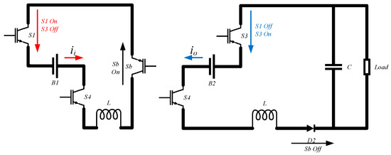 Figure 13. Simplified topology of the balancing mode when using load in small-signal modeling.
The average state equation for balancing mode when using load is as follows:
Introducing AC perturbations into the above equation yields
The small-signal model can then be written as
The above equation can be obtained by applying Laplace transform, as follows:
The transfer function can be obtained from Equations (15) and (16):
Next, the PI controller parameters Kpc and Kic are calculated to obtain the desired phase margin for the inner current control loop. The Bode plot of the inner loop is shown in Figure 11b, and indicates that the system is stable as the open-loop phase margin at the cutoff frequency is greater than zero.
- 2.
- Design of the outer voltage control loop: Due to the high bandwidth and fast current control characteristics of the inner loop, the transfer function of the inner current control loop can be neglected in the design of the voltage controller. Therefore, the duty cycle D can be assumed constant, and its transfer function is
Then calculate the PI controller parameters Kpv and Kiv to obtain sufficient open-loop phase margin at the required cutoff frequency. Figure 11c shows the Bode diagram of the external voltage control circuit. The phase margin at the cut-off frequency is greater than zero, and the system is stable. Parameters of the control system designed as described in Section 3 are given in Table 2.
Table 2.
Parameters of the control system.
4. Simulation Results
To verify the effectiveness of the above SOC balancing strategy, a system model with five battery cells was built and simulated using Simulink for validation, and compared with the balancing strategy described in [26]. The balancing strategy described in [26] can be summarized as the discharge of the battery module with the highest level of charge to the entire battery module, but this will lead to the repeated charging and discharging of the battery module with the highest level of charge. It is worth noting that only three battery modules were used in [26], but in order to better illustrate the balancing strategy, this article uses five battery modules for simulation, and the same settings can be applied to more battery modules. When the control system detects that the difference between the maximum and minimum SOC of the battery module exceeds the set value, the balancing starts until the SOC of all battery modules reaches equilibrium, and the balancing process ends. The simulation model adopts a lithium-ion battery equivalent to 18,650 batteries, with a rated voltage of 3.7 V and capacity of 2000 mAh. The switching frequency is 20 kHz, the inductance is 2 mH, and the capacitance is 220 μF. SOC1~SOC5 are 59.5%, 59%, 60%, 58%, and 58.5%, respectively. The basic parameters of various devices are shown in Table 3. The overall block diagram of the system simulation is shown in Figure 14. Set the system step time simulation to 2.5 × 10⁻⁵ s. Note: the purpose of setting a smaller SOC difference between batteries is to accelerate simulation time to verify the effectiveness of the proposed balancing strategy.
Table 3.
Parameters of simulation experiment.

Figure 14.
System simulation block diagram.
4.1. Balanced Simulation When No Load Is Used
When no load was used, the balancing current was set to 1 A for the simulation experiment. To verify the effectiveness of the proposed new balancing control scheme, a comparison and analysis were conducted with the balancing strategy proposed in [26]. The SOC variation, balancing current, and output voltage of the battery module under the two balancing strategies are shown in Figure 15 and Figure 16, respectively. The equilibrium time and integral of squared error criterion (ISE) of the two balancing strategies are shown in Table 4. Under the new balancing strategy, the battery module SOC reaches equilibrium in approximately 219 s, while the balancing strategy in [26] achieved equilibrium at around 415 s. The proposed balancing strategy improves the balancing speed by approximately 47.2%, with the balancing current remaining stable around 1 A, and its current ripple being relatively small, the ISE is approximately 0.267. Compared with the balance strategy in [26], the ISE is approximately 1.849, indicating that the new balancing strategy has better balancing performance.

Figure 15.
Simulation of the proposed balancing strategy when no load is used: (a) SOC variations of battery modules; (b) balanced current.
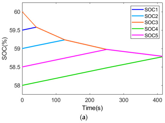
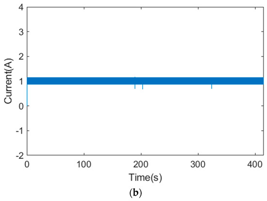
Figure 16.
Balanced simulation when no load is used in [26]: (a) SOC variations of battery modules; (b) balanced current.
Table 4.
Battery equalization time and the size of current ISE when no load is used.
4.2. Balanced Simulation When Using Load
When a load was used, the output voltage was set to 15 V for the simulation experiment. The SOC variation, balancing current, and output voltage of the battery module under the two balancing strategies are shown in Figure 17 and Figure 18, respectively. The equilibrium time and ISE of the two balancing strategies are shown in Table 5. The battery module SOC reaches equilibrium at approximately 242 s with the proposed new balancing strategy, while the balancing strategy in [26] reached equilibrium at around 416 s. The proposed balancing strategy improves the balancing speed by approximately 41.8%. The balancing current in the proposed new balancing strategy remains stable at around 1 A, and the output voltage stays stable at 15 V with relatively small current ripple and voltage ripple, the ISE of the output voltage is approximately 1.686. In contrast, the balancing current in [26] was approximately 1 A, and the output voltage stayed stable at 15 V, and the ISE of the output voltage was approximately 2.517. Therefore, the output voltage ripple of the proposed new balancing strategy is relatively small.
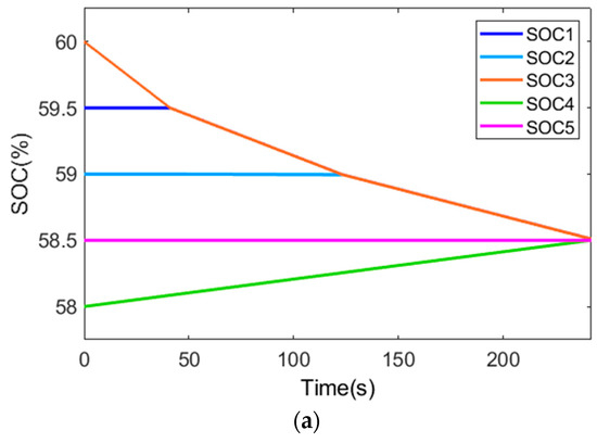
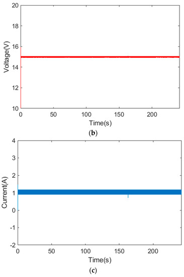
Figure 17.
Simulation of the proposed balancing strategy when using load: (a) SOC variations of battery modules; (b) output voltage; (c) balanced current.
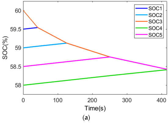
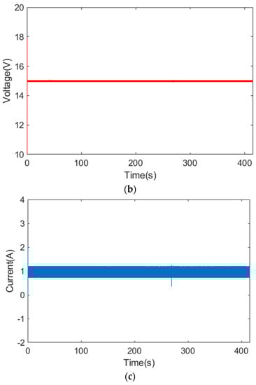
Figure 18.
Simulation of the balancing strategy when using load in [26]: (a) SOC variations of battery modules; (b) output voltage; (c) balanced current.
Table 5.
Battery equalization time and the size of voltage ISE when load is used.
To further validate the effectiveness of the proposed equilibrium strategy, the SOC value of the battery was modified to align with the approach presented in [26]. The SOC values of batteries B1 to B5 are set to 80%, 79.5%, 79%, 78.5%, and 78%, respectively. Subsequently, the simulation was conducted once again. This adjustment was made to ensure consistency and enable a comprehensive evaluation of the proposed strategy’s performance.
In the simulation experiment, when there was no load, the balancing current was set to 1 A. The SOC variations and balancing current of the battery modules are illustrated in Figure 19 and Figure 20, respectively. The equilibrium time and ISE of the two balancing strategies are shown in Table 6. With the new balancing strategy, the battery module’s SOC reaches equilibrium in approximately 218 s, whereas the balancing strategy described in [26] achieved equilibrium at around 411 s. The proposed balancing strategy improves the balancing speed by approximately 47.0%. Additionally, the ISE for the balancing current in the proposed equilibrium strategy is approximately 0.268, whereas the ISE for the balancing current in [26] was approximately 1.845.

Figure 19.
Simulation of the proposed balancing strategy without using load: (a) SOC variations of battery modules; (b) balanced current.
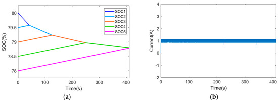
Figure 20.
Balanced simulation of unused load in [26]: (a) SOC variations of battery modules; (b) balanced current.
Table 6.
The second working condition-Battery equalization time and the size of current ISE when no load is used.
In the simulation experiments using a load, the output voltage was set to 15 V. The SOC variations and output voltage of the battery module under the two balancing strategies are depicted in Figure 21 and Figure 22, respectively. The equilibrium time and ISE of the two balancing strategies are shown in Table 7. With the proposed new balancing strategy, the battery module’s SOC reaches equilibrium at approximately 244 s, while the balancing strategy mentioned in [26] achieved equilibrium at approximately 413 s. The proposed balancing strategy improves the balancing speed by approximately 40.9%. In terms of the output voltage, the ISE for the proposed strategy is approximately 1.683, whereas the ISE for the strategy in [26] was approximately 2.514. Hence, the proposed new balancing strategy exhibits relatively small output voltage ripple.
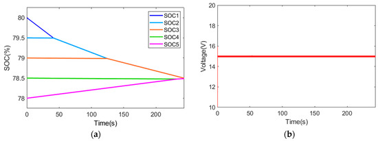
Figure 21.
Simulation of the proposed balancing strategy when using load: (a) SOC variations of battery modules; (b) oOutput voltage.

Figure 22.
Simulation of the balancing strategy when using load in [26]: (a) SOC variations of battery modules; (b) output voltage.
Table 7.
The second working condition-Battery equalization time and the size of voltage ISE when load is used.
Based on the above simulation results, the following conclusions can be drawn:
- The newly proposed equalization strategy results in a significant enhancement of balancing speed, regardless of the presence or absence of load.
- Without utilizing load balancing, the equalizing current remains at 1 A. With the implementation of the new strategy, the current ripple is reduced, indicating an improvement in system stability.
- When using load, where the output voltage on the load is set to 15 V, the new balancing strategy demonstrates diminished voltage ripple, which implies an augmentation in overall system stability.
5. Discussion
The proposed new balancing strategy showed significant improvements in balancing speed compared to the balancing strategy described in [26]. Furthermore, there was a certain enhancement in system stability, indicated by the reduced current ripple and voltage ripple during balancing. This can be attributed to the fact that the balancing strategy operates on a single-cell-to-single-cell basis, transferring energy from the battery with the highest state of charge to that with the lowest state of charge, thereby avoiding repeated charge and discharge cycles in certain batteries. However, the limitation of this balancing strategy lies in the need for a larger duty cycle when load balancing is performed. This is due to the fact that only one battery is supplying power during the process, necessitating a higher duty cycle to meet the requirements of output voltage. However, it should also be noted that this integrated reconfigurable converter system only enables adjacent batteries to be connected in series in order to supply power together, and cannot bypass intermediate batteries. For instance, B1 and B2 can be connected in series to simultaneously supply power to the load, but B1 and B3 are unable to be connected in series with the load by bypassing B2. This limitation provides potential for improvement in future research.
6. Conclusions
In this paper, an improved battery balancing strategy was presented for application in integrated reconfigurable converter systems. The integrated reconfigurable converter system combines a reconfigurable battery system with a converter system, which can be configured into different operating modes based on the battery’s state: supplying power to the load mode and balancing mode. When supplying power to the load without the need for battery balancing, the reconfigurable battery system combined with a boost converter can select the input voltage according to the demand. When there is a significant charge difference between the batteries and the system enters the balancing mode, the improved balancing strategy allows balancing to be performed both during no-load conditions and while supplying power to the load. The balancing mode adopts a PI controller for control, and a simulation model was established using MATLAB/Simulink to validate the effectiveness of the simulation strategy and compare it with previous strategies. The simulation results demonstrate that regardless of the presence or absence of a load during balancing, the balancing speed is improved, and the system’s stability is also enhanced.
Author Contributions
Conceptualization, G.W. and Q.Z.; methodology, G.W. and M.L.; software, G.W.; validation, M.L., S.L., Z.F. and J.L.; formal analysis, Q.Z.; investigation, Z.F.; resources, J.L.; data curation, G.W.; writing—original draft preparation, G.W.; writing—review and editing, Q.Z.; visualization, M.L.; supervision, S.L. and G.L.; project administration, Q.Z.; funding acquisition, Q.Z. and G.L. All authors have read and agreed to the published version of the manuscript.
Funding
This research was funded by the Natural Science Foundation of Shandong Province, China (ZR2021ME163) and the Key Research and Development Program of Shaanxi Province (No. 2022NY-203).
Data Availability Statement
The data that support the findings of this study are available from the corresponding author upon reasonable request.
Conflicts of Interest
The authors declare no conflict of interest.
References
- Daowd, M.; Antoine, M.; Omar, N.; Van den Bossche, P.; Van Mierlo, J. Single Switched Capacitor Battery Balancing System Enhancements. Energies 2013, 6, 2149–2174. [Google Scholar] [CrossRef]
- Zun, C.-Y.; Park, S.-U.; Mok, H.-S. New Cell Balancing Charging System Research for Lithium-ion Batteries. Energies 2020, 13, 1393. [Google Scholar] [CrossRef]
- Xu, J.; Li, S.; Mi, C.; Chen, Z.; Cao, B. SOC Based Battery Cell Balancing with a Novel Topology and Reduced Component Count. Energies 2013, 6, 2726–2740. [Google Scholar] [CrossRef]
- Zhang, D.-H.; Zhu, G.-R.; He, S.-J.; Qiu, S.; Ma, Y.; Wu, Q.-M.; Chen, W. Balancing Control Strategy for Li-Ion Batteries String Based on Dynamic Balanced Point. Energies 2015, 8, 1830–1847. [Google Scholar] [CrossRef]
- Zhang, Y.; Liu, Z.; Chen, Z. Smart-Leader-Based Distributed Charging Control of Battery Energy Storage Systems Considering SoC Balance. Batteries 2023, 9, 18. [Google Scholar] [CrossRef]
- Daowd, M.; Antoine, M.; Omar, N.; Lataire, P.; Van Den Bossche, P.; Van Mierlo, J. Battery Management System—Balancing Modularization Based on a Single Switched Capacitor and Bi-Directional DC/DC Converter with the Auxiliary Battery. Energies 2014, 7, 2897–2937. [Google Scholar] [CrossRef]
- Van, C.N.; Vinh, T.N.; Ngo, M.-D.; Ahn, S.-J. Optimal SoC Balancing Control for Lithium-Ion Battery Cells Connected in Series. Energies 2021, 14, 2875. [Google Scholar] [CrossRef]
- Cui, X.; Shen, W.; Zhang, Y.; Hu, C. A Novel Active Online State of Charge Based Balancing Approach for Lithium-Ion Battery Packs during Fast Charging Process in Electric Vehicles. Energies 2017, 10, 1766. [Google Scholar] [CrossRef]
- Nishijima, K.; Sakamoto, H.; Harada, K. A PWM controlled simple and high performance battery balancing system. In Proceedings of the 2000 IEEE 31st Annual Power Electronics Specialists Conference. Conference Proceedings (Cat. No. 00CH37018), Galway, Ireland, 23 June 2000; IEEE: Piscataway, NJ, USA, 2000; pp. 517–520. [Google Scholar]
- Li, S.; Mi, C.C.; Zhang, M. A high-efficiency active battery-balancing circuit using multiwinding transformer. IEEE Trans. Ind. Appl. 2012, 49, 198–207. [Google Scholar] [CrossRef]
- Cao, Y.; Qahouq, J.A.A. Hierarchical SOC balancing controller for battery energy storage system. IEEE Trans. Ind. Electron. 2020, 68, 9386–9397. [Google Scholar] [CrossRef]
- Wang, Y.-X.; Zhong, H.; Li, J.; Zhang, W. Adaptive estimation-based hierarchical model predictive control methodology for battery active equalization topologies: Part I–Balancing strategy. J. Energy Storage 2022, 45, 103235. [Google Scholar] [CrossRef]
- Yun, Z.; Qin, W.; Shi, W.; Wu, C. Research on active state of charge balance of battery pack based on two controllable flyback converters. J. Energy Storage 2023, 57, 106183. [Google Scholar] [CrossRef]
- Li, Y.; Yin, P.; Chen, J. Active Equalization of Lithium-Ion Battery Based on Reconfigurable Topology. Appl. Sci. 2023, 13, 1154. [Google Scholar] [CrossRef]
- Engelhardt, J.; Zepter, J.M.; Gabderakhmanova, T.; Rohde, G.; Marinelli, M. Double-String Battery System with Reconfigurable Cell Topology Operated as a Fast Charging Station for Electric Vehicles. Energies 2021, 14, 2414. [Google Scholar] [CrossRef]
- Haller, S.; Alam, M.F.; Bertilsson, K. Reconfigurable Battery for Charging 48 V EVs in High-Voltage Infrastructure. Electronics 2022, 11, 353. [Google Scholar] [CrossRef]
- Karunathilake, D.; Vilathgamuwa, M.; Mishra, Y.; Corry, P.; Farrell, T.; Choi, S.S. Degradation-Conscious Multiobjective Optimal Control of Reconfigurable Li-Ion Battery Energy Storage Systems. Batteries 2023, 9, 217. [Google Scholar] [CrossRef]
- Tashakor, N.; Dusengimana, J.; Bayati, M.; Kersten, A.; Schotten, H.; Götz, S. General Decoupling and Sampling Technique for Reduced-Sensor Battery Management Systems in Modular Reconfigurable Batteries. Batteries 2023, 9, 99. [Google Scholar] [CrossRef]
- Wang, S.; Liu, D.; Zhou, J.; Zhang, B.; Peng, Y. A Run-Time Dynamic Reconfigurable Computing System for Lithium-Ion Battery Prognosis. Energies 2016, 9, 572. [Google Scholar] [CrossRef]
- Ci, S.; Lin, N.; Wu, D. Reconfigurable battery techniques and systems: A survey. IEEE Access 2016, 4, 1175–1189. [Google Scholar] [CrossRef]
- Xu, J.; Cao, B.; Wang, J. A Novel Method to Balance and Reconfigure Series-Connected Battery Strings. Energies 2016, 9, 766. [Google Scholar] [CrossRef]
- Han, W.; Zou, C.; Zhou, C.; Zhang, L. Estimation of cell SOC evolution and system performance in module-based battery charge equalization systems. IEEE Trans. Smart Grid 2018, 10, 4717–4728. [Google Scholar] [CrossRef]
- Momayyezan, M.; Hredzak, B.; Agelidis, V.G. Integrated reconfigurable converter topology for high-voltage battery systems. IEEE Trans. Power Electron. 2015, 31, 1968–1979. [Google Scholar] [CrossRef]
- Momayyezan, M.; Hredzak, B.; Agelidis, V.G. A load-sharing strategy for the state of charge balancing between the battery modules of integrated reconfigurable converter. IEEE Trans. Power Electron. 2016, 32, 4056–4063. [Google Scholar] [CrossRef]
- Morstyn, T.; Momayyezan, M.; Hredzak, B.; Agelidis, V.G. Distributed control for state-of-charge balancing between the modules of a reconfigurable battery energy storage system. IEEE Trans. Power Electron. 2015, 31, 7986–7995. [Google Scholar] [CrossRef]
- Zhao, C.; Liu, S.; Fan, B. State of Charge Balancing Control for Battery System Based on the Reconfigurable Converter. In Proceedings of the 2021 IEEE 5th Conference on Energy Internet and Energy System Integration (EI2), Taiyuan, China, 22–24 October 2021; IEEE: Piscataway, NJ, USA, 2021; pp. 4215–4220. [Google Scholar]
Disclaimer/Publisher’s Note: The statements, opinions and data contained in all publications are solely those of the individual author(s) and contributor(s) and not of MDPI and/or the editor(s). MDPI and/or the editor(s) disclaim responsibility for any injury to people or property resulting from any ideas, methods, instructions or products referred to in the content. |
© 2023 by the authors. Licensee MDPI, Basel, Switzerland. This article is an open access article distributed under the terms and conditions of the Creative Commons Attribution (CC BY) license (https://creativecommons.org/licenses/by/4.0/).