Article

Energy Storage Management of a Solar Photovoltaic–Biomass Hybrid Power System

by
Oluwaseun Olanrewaju Akinte
1,
Boonyang Plangklang
1,*,
Boonrit Prasartkaew
2 and
Taiwo Samuel Aina
3
1
Department of Electrical Engineering, Faculty of Engineering, Rajamangala University of Technology Thanyaburi, Pathum Thani 12110, Thailand
2
Department of Mechanical Engineering, Faculty of Engineering, Rajamangala University of Technology Thanyaburi, Pathum Thani 12110, Thailand
3
Department of Computer Science and Technology, University of Bedfordshire, Vicarage St., Luton LU1 3JU, UK
*
Author to whom correspondence should be addressed.
Energies 2023, 16(13), 5122; https://doi.org/10.3390/en16135122
Submission received: 17 January 2023 / Revised: 11 February 2023 / Accepted: 15 February 2023 / Published: 3 July 2023
(This article belongs to the Special Issue Materials and Energy in Negative and Neutral Carbon Society)

Abstract

:
Remote areas that are not within the maximum breakeven grid extension distance limit will not be economical or feasible for grid connections to provide electrical power to the community (remote area). An integrated autonomous sustainable energy system is a feasible option. We worked on a novel multi optimization electrical energy assessment/power management system of a microgrid network that adopted combined dispatch, load-following, and cycle-charging strategies (control system) that acted as a power interface module over the hybrid configuration of energy sources (grid network/downdraft biomass generator/solar photovoltaic), thermal load controller-boiler systems, and hybrid energy-storage technologies (lithium, iron flow, sodium sulfur, and flywheel) to enable the microgrid network to operate in the island (off grid), grid, and island-able (ability to isolate itself when it is connected to the grid network) modes efficiently and effectively. An optimal multitask control algorithm and the storage units of modeled power generation sources were executed with the HOMER software application to improve the energy system’s efficiency, promote effective storage management, minimize energy loss, and improve the lifespan of the microgrid network. The integrated energy system can work for both rural and urban areas.

1. Introduction

The concept of a microgrid is to function as an independent energy source, a power-system-controlled cell from the perspective of utility service, and to have a distribution of energy resources with thermal/electrical loads that can be controlled to meet energy demand requirements, continue in power supply, reduce energy losses from the feeder system, minimize voltage sagging, and improve the system’s efficiency from the consumer’s point of view [1]. The utility grid as an upstream system for electrical power production uses solar photovoltaic plants (PV panels), conventional generators (diesel power plants), hydropower plants, hydrogen/fuel cells, and wind power plants with storage systems such as ultracapacitors, batteries, flywheels, etc. Several studies, including pilot projects whereby the authors installed utility grids in different geographical areas where renewable energy systems are utilized locally to form an integrated hybrid microgrid energy system to supply electricity to houses in a local area at a minimized cost independent of grid connection, have been designed [2,3,4]. The energy cost is reduced compared to conventional (fossil fuel) energy generation, thereby making it comfortable for inhabitants in the isolated community (geographical areas with good telephone networks and utility grid connections with scheduled appointment flight services without access to yearly round roads) whose geographical area location is below 300 km from the nearest center of electrical network services. Alternative energy sources are available or easily replaced on a never-ending, frequent, or repeated-occurrence basis if they can be properly managed. Renewable energy poses some challenges in a technical way such as the degradation in power quality, unstable frequency, sagging of voltage, insecurity in the power system, and issues with reliability [5,6]. For stable operation maintenance, reserve power is required by a conventional generator or energy storage units. The conventional system poses a threat to the human environment by using fossil fuels. A rise in fuel costs and the issue of availability in remote areas make conventional power plant microgrid systems economically unviable.
Due to the enormous capability of energy storage and the market development rise, efforts on several research extensions have been conducted for comprehensive review and research provision on the categories, usage, and system evaluation of energy storage systems in an integrated hybrid power system. Patel and Singal [7] investigated 123 electrified households with an off-grid system in the Rajasthan/Gujarat border in India consisting of a hybrid system (solar PV/biomass gasifier biogas generators/wind turbine/lead–acid battery) using the multivariable linear regression method, particle swarm optimization, and gradient descent algorithm. Ramesh and Saini [8] researched a hybrid solar PV/wind turbine/diesel generator/micro-hydro/lead–acid/lithium-ion battery in Chikamagalur district, India, in an off-grid unelectrified village using HOMER power tool software to provide a minimized energy and net present costs when compared to a controller (cycle charging and load follower)-based system with the lead–acid battery strategy. Upadhyay and Sharma [9] investigated seven electrified off-grid villages with a hybrid configuration of solar PV/micro-hydro power/biomass gasifier/biogas generators/diesel plant/lead–acid batteries by using load following/cycle charging based biogeography optimizer/a genetic process algorithm/particle process swarm optimization strategies at Uttarakhand, India, to obtain based biogeographical algorithm optimization result. Rajanna and Saini [10] researched five unelectrified off-grid villages in Chamarajanagar district, India, with a hybrid configuration of solar PV–wind turbine–microhydro power–biomass gasifier–biogas generators/lead–acid battery/the genetic algorithm processed strategy. Bhatt et al. [11] studied five electrified off-grid villages that were unelectrified in Almora district, India, with a hybrid configuration of solar PV/micro-hydro power/biomass gasifier/biogas generator/diesel plant/lead–acid batteries by applying HOMER power tool software analysis for the net-present cost minimization of the hybrid network. Shezan et al. [12] researched a grid-independent village at the station of Klia Sepang, Malaysia, with a hybrid form of solar PV/wind turbine/diesel plant/lead–acid batteries using HOMER power tool software for the minimization of the net-present cost values of the hybrid network. Durlinger et al. [13] conducted analytical research on solar PV lighting products’ life cycle in Southeast Asia in an off-grid rural area through the application of Simapro power tool software and concluded that solar PV lightings possess below conventional lighting in terms of environmental impact. Pina et al. [14] investigated a grid-independent rural area (electrified) with a hybrid setting of a solar PV/diesel plant/lead–acid batteries using HOMER power tool software to minimize the net-present cost value of the hybrid network in Cambodia. Rodriguez-Gallegos et al. [15] investigated an electrified island (off grid) system in Indonesia with a hybrid form of solar PV/diesel plant/lithium-ion batteries using a genetic algorithm. Kim and Yong [16] investigated an electrified grid-independent remote area with a hybrid formation of solar PV/diesel plant/lead–acid–lithium-ion batteries in Myanmar using HOMER power tool software to minimize the net-present cost value in the hybrid system by obtaining an optimal result from lead–acid batteries. Kohsri et al. [17] investigated an off-grid system through the hybrid formation of solar PV/biomass gasifier/lithium-ion batteries in Thailand by using LabVIEW power tool software. Lozano et al. [18] investigated electrified island (off grid) systems in the Philippines, Cordova, Gilutongan, and Cebu with a hybrid configuration of solar PV/lead–acid batteries using HOMER power tool software to minimize the net-present cost for the hybrid network. Moretti et al. [19] electrified a rural community with the hybrid integration of solar PV/diesel plant/lead–acid–lithium-ion batteries in Sub-Saharan Africa by using a pattern search and integer linear program method to increase the system’s reliability, reduce the cost of energy, and increase the sustainable energy penetration in the network. Ciez and Whitacre [20] conducted research in a rural area (off grid) with a combination of solar PV/diesel plant/lead–acid–lithium-ion batteries using a power flow optimizer with variables in the charging state, renewable energy proportion requirements, the number of batteries to be replaced, types of batteries, and discount ratings through a time-step degradation analysis. Merei et al. [21] conducted research on a rural area with a global system for mobile communication and universal mobile telephone alongside two sites in Quneitra, Syria, and Aachen, Germany with a hybrid system of solar PV/wind plant/vanadium redox-flow lead-concentrated acid–lithium-ion batteries/diesel plant by using a genetic algorithm to generate optimization result from the vanadium redox flow storage unit. Moretti et al. [22] studied an integrated system of solar PV/diesel plant/lead–acid/lithium-ion batteries for locations in Somalia and Garowe by adopting the combination of a heuristic algorithm and integer linear program with the application of energy management in two layers. Kaabeche and Bakelli [23] investigated the hybrid configuration of solar PV/wind plant/lead-acid/lithium-ion and nickel–cadmium batteries through the minimization of electric unit cost by adopting Jaya, grey wolf, Krill herd, and ant lion optimizations at Adrarin state, Algeria, and concluded that the Jaya algorithm/lead–acid/lithium-ion and nickel–cadmium battery provided a feasible solution. Paul et al. [24] studied a hybrid formation of solar PV/wind power plant/diesel plant/lead–acid–lithium-ion batteries in Dodoma, Tanzania by obtaining a minimization of energy cost from lithium-ion batteries through an applied genetic algorithm. Luo et al. [25] investigated 280 households (off grid) with a hybrid configuration of wind power plant/diesel plant/zinc bromide/lead–acid and lithium-ion batteries in Gansu province, China using HOMER power tool software to obtain the optimization for the zinc bromide battery. Synthetic inertia can be provided by battery storage units through a power electronics controller. The stability of voltage, leveling of load consumption, energy reservation, frequency stability, and peak shaving are parts of the applications supported by the battery energy storage unit towards the utility grid system [26,27,28,29]. The application and required system in redundance are a function of the battery’s bank size resulting in different costs for each application [30,31]. The battery energy storage units used for load leveling will attract a higher size and battery bank cost than the storage unit designated for frequency stability and virtual inertia [32,33]. Limitations in the life cycle and the high cost of installation are challenges with battery energy storage systems (BESS). There are elongated years in payback periods for the usage of BESS, which is a function of the application, thereby causing widespread limitation usage in the industrial power sector [34,35]. The charging/discharging rate, operational temperatures, overcharging, and deep discharge depth of batteries have an adverse effect on their performance and lifespan. A decrease in the battery’s performance alongside each cycle with degradation in the electrodes becomes permanent. The increment in the internal resistance of the battery can be applied as a battery life indicator, and hence the tracking and record keeping of the aging of batteries is a challenge while in operation. Chen et al. [36] and Taehoon et al. [37] reviewed the energy of hydrogen history in the power market, energy storage, and thermal industry with the analytical problems encountered in the development of hydrogen energy, and the irreplaceable energy of hydrogen’s position in the future structures of energy was emphasized. Wenchao et al. [38] and Theodosios et al. [39] introduced the latest development of lithium-ion, potassium-ion, and zinc-ion batteries with an update on electrolytes coverage, materials of electrodes, properties, and advantages/disadvantages of ion batteries.
Hybrid power system control in cooperation with solar–wind power similarity and energy storage units were addressed in [40,41]. Focusing on microgrids-based renewable energy power generators with a single battery energy storage system backup, more discussion on the strategies of control for a share in energy and the operations of ancillary services were highlighted. Energy management systems with distributed battery energy storage systems have been practically established [42,43] with a discussion on the voltage and frequency regulations of the utilization of microgrids/smart grids through BESS distribution. Grid stability is a focus of control schemes, operating as regulations in the battery’s charging state without consideration of its state of health or supplying capacity. The discussion in [44] models the battery management system scale of the grid for Li+ (lithium-ion) and Pb2+ (lead–acid) batteries, focusing on regulating the batteries’ strategic control over their state of charge. Aqib et al. [45] reviewed lithium-ion battery development and proposed lithium–air and lithium–sulfur, which can possess better theoretical performance than the traditional lithium-ion battery. Poonam et al. [46] and Bruce et al. [47] summarized the ultracapacitors with respect to their process of development, criteria for classification, and storage mechanism alongside detailed categories of electrode–electrolyte material applications in ultracapacitors and an analysis of corresponding material properties. Kumar and Saini [48] introduced several secondary cell batteries including sodium–sulfur batteries, redox flow batteries, and lithium-ion batteries, and their electrochemical properties, structures, and historical developments were described in detail by comparing their performance with other energy-storage technologies. The above information from the literature review of several authors indicates that the research on an integrated (biomass gasifier/dedicated solar PV plant/flywheel/NaS-Fe flow and Li-NMC oxide batteries/thermal load controller boiler) hybrid energy system’s operation between the thermal/consumer loads, power generation sources, and storage systems are yet to be identified. As most of the previous research deliberated on feasible technology and economic reports by analyzing one or more batteries to continuously supply electric power and have differentiated between robust and convergent power ratios of more than one algorithm proposal.
A new proposal was designed by using a novel optimal multitask control algorithm, control system (load-following, combined dispatch, and cycle-charging) strategy, and a thermal load controller to serve as an interface module over the primary energy sources, storage systems, and AC load capacity in order to achieve efficient power transmission, power optimization, reliable control measure, power quality control, and the minimization of losses within the integrated energy system configuration by applying HOMER PRO power tool software along with the design. The control system of the hybrid power network consisted of a load follower/cycle charging/combined dispatch processor to interface over the grid network, renewable power sources, load demand, and storage units. The power quality device (high-frequency flywheel) played three important roles: a spinning reserve, an additional power system support that improved the power quality by receiving energy from the grid system and renewable power sources as a motor, and a generator to assist in energizing the batteries and AC loads to the hybrid network configuration. Another modeled device called the thermal load controller acted as a thermal energy consumer between the generating sources, storage units, and AC loads. It (generic boiler–thermal load controller) assists in the coordination of electric power supply over the generating sources, load demand, and storage units by limiting the quantity of electricity that the load can absorb from the power sources, thereby providing a guide against unwanted losses. This hybrid power system concept has a multicontrol system function that can conveniently operate in an orderly manner to affect an efficient, reliable, and well-optimized energy transformation positively for both grid-connected, island (off grid), and island-able power systems by reducing emissions to a minimum level.

Scope of the Proposed Research (Aims and Objectives)

A designed algorithm known as novel multitask controller optimization processing was developed for a modeled integrated power network microgrid system to operate either with a grid or an off-grid connection in the Lopburi community, Thailand, through the utilization of the available solar insolation and biomass resources within the community. The aim of modeling this hybrid energy network is to explore the available sustainable energy resources (solar insolation and biomass fuel) and determine the optimization of the energy system’s configuration in meeting the desired energy demand to ensure stability between the generating energy sources (solar PV/biomass), storage unit, and load (peak shaving and load leveling). This will allow the hybrid energy network to achieve real-time stability with nonuniform AC loads on the network (grid/off grid) mode of operation (voltage and frequency regulation) by providing backup power and preventing source outage (emergency energy reserve system) through the application of hybrid energy reserve systems (Li, Fe, NaS batteries and flywheel). It will also eliminate voltage sagging and power fluctuation problems from the microgrid power network, which will allow one to examine the behavioral effect in terms of uncertainty from the components of the storage units on the microgrid system technology by establishing a multi-control system with a multifunctional task. Finally, this will also allow one to prove that the integrated microgrid energy system is more effective than the conventional (fossil fuel) energy system in terms of emission, efficiency, and flexibility.

2. Proposed Control Algorithm Strategy

Figure 1 shows the flow chart of the optimal control algorithm strategy for the integrated hybrid renewable energy microgrid system network, which consists of eight different satisfactory conditions for its successful and efficient outcome in terms of operational delivery from the solar PV, biomass generator, and utility grid when their sources (primary source) of energy are deficient or out of operation. The batteries’ (Li, Fe, NaS) supplying capacities will stabilize the intermittent (unstable solar irradiation penetration) power supply from the solar photovoltaic plant when it is operating below the load capacity. High-energy flywheel storage will improve the power quality transmission and assist in balancing the deficit power between the hybrid power sources and energy demand from the isolated community, respectively.
The hybrid energy sources consist of the solar photovoltaic power plant, biomass gas generator plant, utility power grid (which may have been connected or disconnected from the hybrid renewable energy system), storage units (batteries/flywheel), and microgrid controller (cycle charging, load follower, and combined dispatch).

Power Stability Algorithm for the Integrated Energy System

In the above hybrid power system network, the microgrid controller coordinates the integrated hybrid power generation by monitoring the batteries’ state of charge, depth of discharge, supplying capacities, deficiency, and excessiveness in electric power flow between the energy sources and load demand and operational routine between the grid and off-grid connection to the hybrid network, enabling the high-energy rotating mass flywheel to act as a spinning reserve in supporting the batteries by making them (the batteries) operate beyond the normal temperature range without any damage. The diversion of excess electricity can be channeled to the deferrable loads with the help of a thermal load controller.
The depicted proposed flow chart of the algorithm in Figure 1 below begins by considering the power plants, utility grid, load demand, and input process as the batteries’ state of charge. The processed data with signals of control are purposely generated for the batteries’ operation and flywheel. The eight possible conditions are stated below.
Mode 1: If the electric energy produced by the solar voltaic plant is greater than the AC load consumption during the active grid connection and nonactive biomass plant operations, (PPVs > PLoads and Pugrid ≠ 0, Pbiomass = 0), and if the batteries are partially charged (SChr(n) ≤ SChr-max), the microgrid controller will signal power flow from the solar PV plant to charge the batteries, store energy on the flywheel, and energize the AC loads at the same time. When the batteries’ flywheel is fully charged, the excess energy flow will energize the deferrable AC loads and sell electricity at the same time to the grid system network.
Mode 2: If the electric energy produced from the solar voltaic plant is greater than the AC load consumption during the off-grid and nonactive biomass plant operation, (PPVs > PLoads and Pugrid = 0, Pbiomass = 0), and if the batteries are partially charged (SChr(n) < SChr-max), the microgrid controller will signal excess power flow to charge the batteries, store energy in the flywheel, and energize the loads at equal period.
Mode 3: If the electric energy produced from the solar voltaic plant is greater than the AC load consumption during the off-grid and nonactive operational biomass plant, (PPVs > PLoads and Pugrid = 0, Pbiomass = 0), and if the batteries are fully charged (SChr(n) = SChr-max), the microgrid controller will signal the excess power generation curtailment to the deferrable AC loads.
Mode 4: If the electric energy produced from the solar voltaic equals the load demand at either on/off-grid and active/nonactive biomass plant operation (PPVs = PLoads and Pugrid = or ≠ 0, Pbiomass = or ≠ 0) then the microgrid controller will signal the power flow directly to the AC loads with no charging operation on the batteries and flywheel.
Mode 5: If the electric energy produced from the solar voltaic is less than the AC load’s consumption during the off-grid, active biomass plant operation, (Ppvs < Ploads, Pugrid = 0, Pbiomas ≠ 0), and if the batteries are partially charged (SChr(n) ≤ SChr-min), the microgrid controller will signal the active operation of the biomass generator to energize the AC loads, charge the batteries, and store energy on the flywheel at the same time.
Mode 6: If the electric energy production from the solar voltaic is less than the load in demand during the off-grid and nonactive biomass plant operation, (Ppvs < Ploads, Pugrid = 0, Pbiomas = 0), and if the batteries are not fully discharged (SChr(n) > SChr-min), then the microgrid controller will signal a power flow discharge command from the batteries and flywheel support to energize the AC loads.
Mode 7: If the electric energy production from the solar voltaic is less than the load in demand during the off-grid and nonactive biomass plant operation, (Ppvs < Ploads, Pugrid = 0, Pbiomas = 0), and if the batteries are not fully charged (SChr(n) <= SChr-min), then the microgrid controller will signal for flywheel assistance to energize the AC loads, and if the flywheel is not available, the controller will call for loading shedding; otherwise, the entire system will be shut down.
Mode 8: If the electric energy production from the solar photovoltaic is less than the AC load consumption during the active grid connection and inactive biomass plant operation, (Ppvs < Ploads, Pugrid ≠ 0, Pbiomas = 0), and if the batteries/flywheel are partially discharged (SChr(n) ≥ SChr-min), the microgrid controller will signal the power flow from the grid network to charge the batteries, store electrical energy on the flywheel, and energize the AC loads/deferrable AC loads at the same time. Table 1 gives the properties of the three different batteries being used for the hybrid power system network.

3. Methods and Materials Application

3.1. Area of Study: Tha Sala (Muang Lopburi)

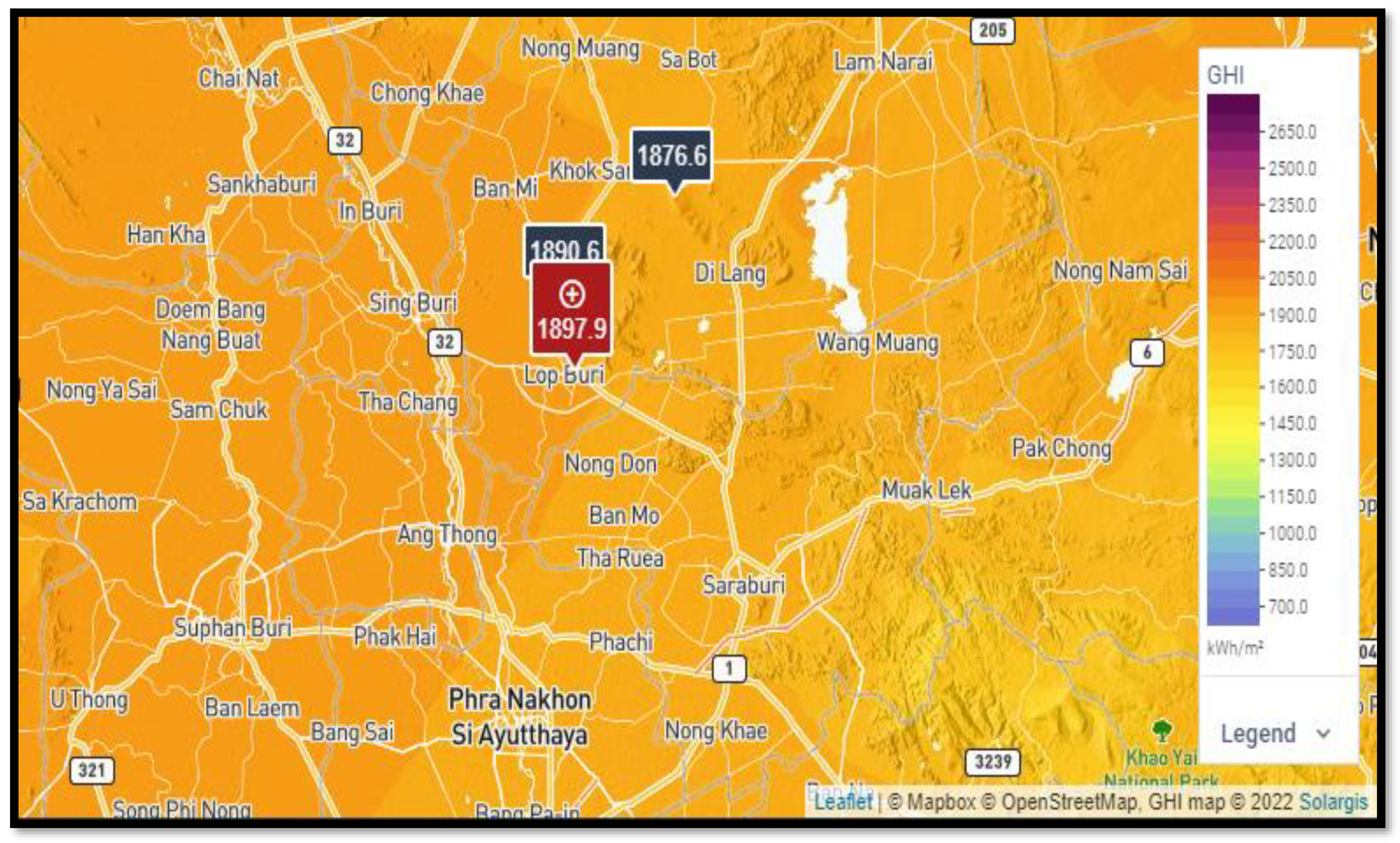
The chosen area of study was based on the potential availability of solar insolation and biomass resources, which was used to design the microgrid network in a grid or island mode (off grid) of operation. The Muang Lopburi district, Lopburi province is located at latitude 14.80° N and longitude 100.65° E in the central region of Thailand as depicted in Figure 2. It has a high concentration of yearly mean solar irradiation of 5.85 kWhm−2day−1 and an ambient temperature of 25.95 °C, as shown in Table 2, with its annual global horizontal irradiation being 1897.9 kWh/m2/yr; the solar radiation hourly data and temperature application were obtained from the Global Solar Atlas database containing the solar irradiation surface assessment, and the biomass resources information was obtained from the Biomass Database Potential and Renewable Energy Outlook in Thailand [49]. The residential, community and commercial loads of the town were obtained from the utility API HOMER Pro microgrid analysis tool and are expressed in Table 3, Table 4 and Table 5 alongside their average loads, peak loads, and load factors.

3.2. Load Profile for Residential, Community, and Commercial Areas of Muang Lopburi

The required energy within the community of Muang Lopburi was assessed through secondary data formulation of the utility API HOMER Pro microgrid analysis tool. The AC load requirement consisted of residential loads, community loads, commercial loads, and deferrable loads. The primary survey data from the Muang Lopburi community gave essential details on domestic appliances being used according to their energy requirements, which were incandescent flood lights, television sets, alternating-current water-pumping machines, direct current mobile charging systems, AC ceiling fans, electric bulbs, water heating elements, etc. The average residential load demand capacity per day was 11.26 kWh/day with an average power rating per day of 0.47 kW. The peak load demand occurred in the month of November at a rated value of 2.09 kW from the seasonal profile. The daily load profile gave a peak demand rating of 1.23 kW at exactly 18:00 p.m. in the residential environment with a load factor of 0.22, which indicated that the maximum (peak) demand was greater than the average demand and that the facilities within the residential area were not operating at full capacity per day, as depicted in the daily profile. Additionally, the load factor value explained an occasional rise in demand within a year.

3.3. Biomass Potential Resources of Lopburi Province

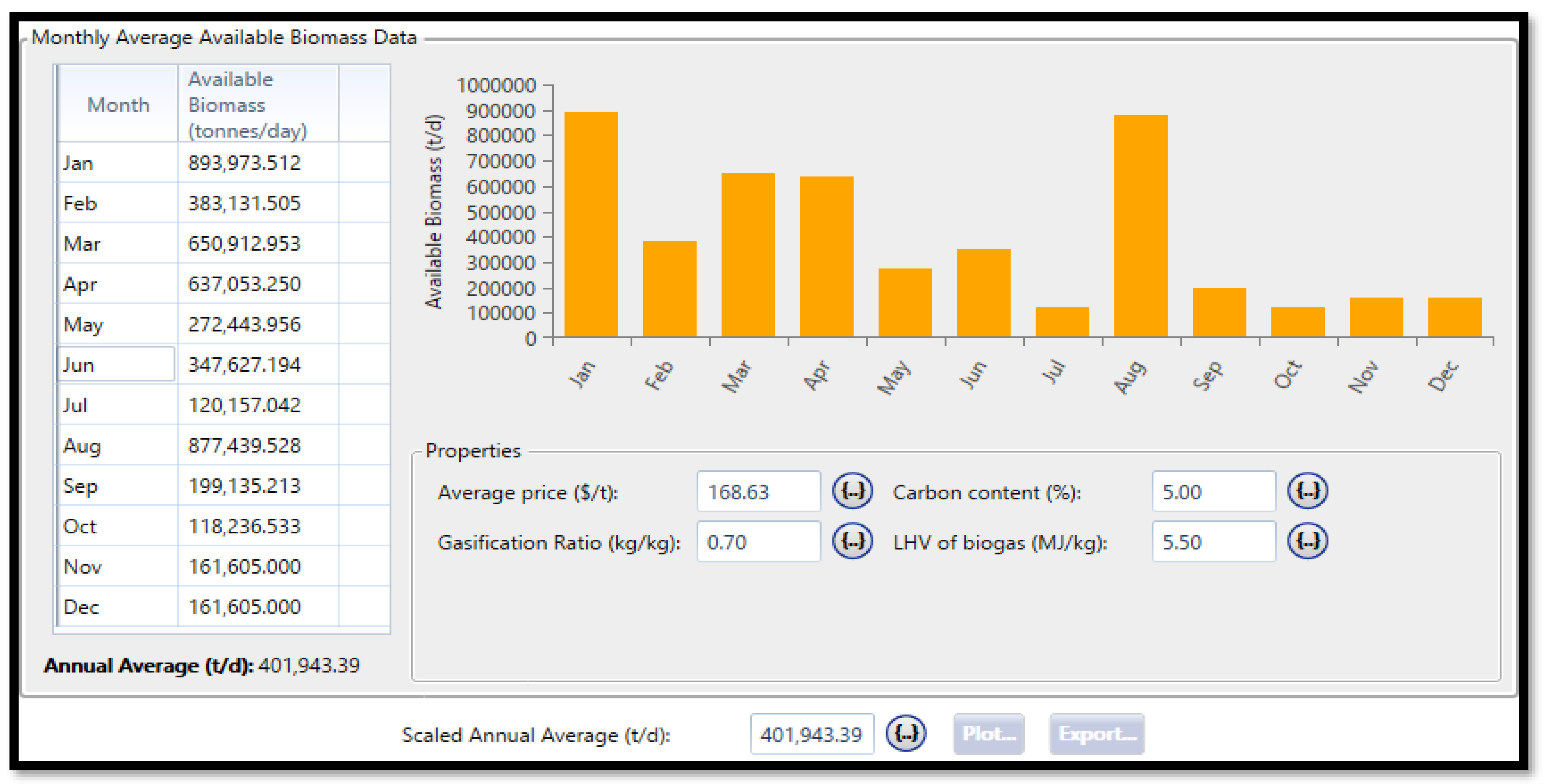
The Lopburi community has a high concentration of biomass resources surrounded by plains and hills for growing sunflowers, millets, sugar cane, tapioca, rice, corn, forests, etc. The monthly biomass resources for this province were given with a yearly biomass average resource of 401,943.39 tonnes/day and an estimation of 146,709,337.35 tonnes generated per year for the biomass fuel potential in the province.
A graphical representation (histogram) of the average monthly biomass resources (rice straw, rice husk, leaves and tops of sugar cane, bagasse, corn stems and leaves, roots of cassava, palm trunk and trees, leaves, branches of palm, empty bunches of palms, palm fibers, deciduous trees, sawdust, slab, swarf rubber wood, forests, branches, stumps, and roots of rubber trees) are also depicted in Figure 3.

3.4. Hybrid Power System Microgrid Network Modeling

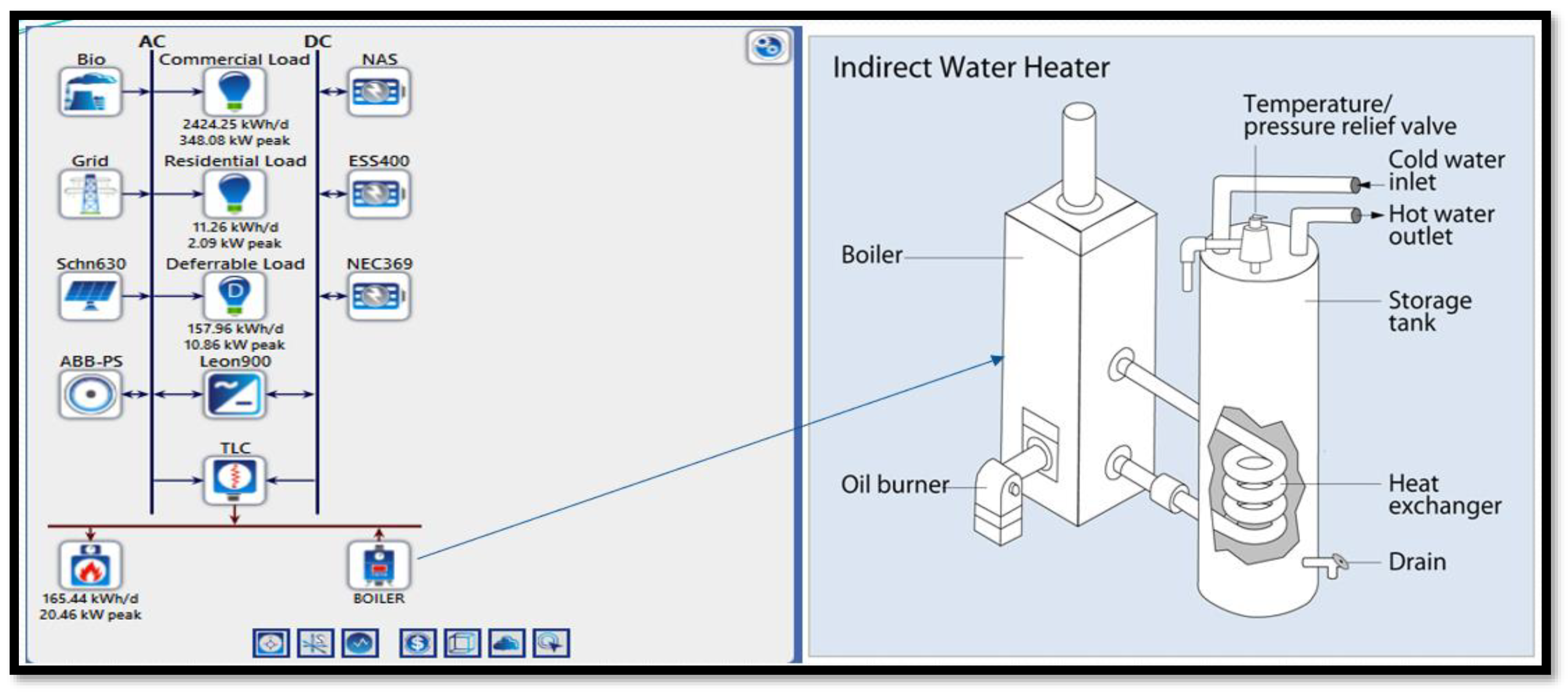
The implementation and validation of the proposed control strategy algorithm for the hybrid system microgrid network were modeled using HOMER power system tool software for the configuration (solar PV plant/biomass gas plant (primary source of energy)/DC optimizer/batteries (Li-NMC, Fe, Nas)/flywheel/utility grid network power provider/power electronics bidirectional converter (AC-DC/DC-AC conversion)/thermal load controller). The potential capacities of the energy system are detailed in Table 6 according to the hybrid power configuration settings from Figure 4.

3.4.1. Solar Photovoltaic Power Plant

There are various solar PV models that are available for the modeling, simulation, and evaluation of the photovoltaic output power. The solar PV plant model with a 630 kW power capacity was chosen from the PV library source of the HOMER software to determine the PV panel output power using Equation (1) below after considering the solar irradiation penetration on the panel per hour and its ambient temperature production per hour in the Lopburi province [51]:
E PVS   ( t ) = E PVr × ( Rt Rreff ) × [ 1 + B T × ( T PC T creff ) ]
where EPVS (t) = the generated output power/hour of the solar photovoltaic array plant (kW), EPVr = the power rating of the photovoltaic panel = 630.03 kW, R(t) = solar irradiation on the panel at the current time step (Wm−2), Rreff = solar irradiation on the panel at S.T.Cs = 1000 Wm−2, BT = temperature coefficient = −0.41%/°C, TPC = nominal operating cell temperature of PV = 45.0 °C, and TCreff = photovoltaic cell temperature at s.t.c = 25 °C.
TPC = Tambt (t) + [2.56 × 10⁻² × R(t)]
where Tambt (t) = ambient temperature produced per hour (°C).
The generated energy by the solar PV panels can be calculated from Equation (2):
SPV (t) = NPVs × EPVs (t) × Δt
where NPVs = the number of PV panels, Δt = the hourly period (1 h), and EPVs (t) = the hourly generated output power from the solar photovoltaic array (kW).
These battery banks were subjected to the following linearity constraints: 0 ≤ Nbatt ≤ Nbatt-max, where Nbatt = the number of batteries used as a storage system.
PSolar PV = ȠSolar PV × PIrra × Aarray
where PSolar PV = the generated power from the solar photovoltaic plant (W), ȠSolar PV = the efficiency of the solar photovoltaic plant = 17.30%, PIrra = the available energy of solar irradiance (Wm−2), Aarray = the area of the PV array (m2).

3.4.2. Biomass Gasifier–Biogas Power Plant

The components of the downdraft gasifier system model comprised a gasification unit of the biomass, a cleaning system for the gases, a cooling system for the gases, and an engine power plant producing the gases. The downdraft gasifier system had a lid of a hopper, dryer zone, pyrolysis zone, zonal combustion, reductional zone, and tank used for removing ashes and smoking valves while the cleaning system of the gases comprised a cyclone system, pan filtering, saw dust filtering, and cotton filtering. The cooling system for the gases comprised chiller’s planting. The output power generated from the biomass gasifier system is expressed mathematically below [51]:
E B . M . G   ( t ) = QB . M . Gs × Ƞ B . M . Gs × CoVB . M . Gs × 1000   DOHB . M . Gs × 365 × 860
where QB.M.Gs = the available biomass quantity (tonnes/year), ȠB.M.Gs = the efficiency of biomass gas = 85%, CoVB.M.Gs = the biomass calorific value = 4.015 × 10³ kilo calorie per Kg, and DOHB.M.Gs = the operation of the biomass gasifier system per day (hours).
The generated output energy of the biomass gasifier system can be calculated as follows:
SB.M.Gs = EB.M.Gs × Δt
where Δt = the operational period of the gasifier system in one hour.

3.4.3. Storage Unit (Li, NaS, Fe batteries) Bank

The batteries (Li, Nas, and Fe) supply electrical power to the loads (residential, community, commercial, and deferrable loads) during demand periods of peak load when the renewable energy sources (solar and biomass plant) are deficient. The batteries are 100% charged when surplus energy from the generating sources is stored in them. The charging/discharging process of the batteries is detailed in the equation(s) below:
If PHRES > PLOAD and SChr < SChr-Max-batt: charging process.
PHRES = power generated from the hybrid renewable energy sources, PLOAD = power from load consumption.
The charging process from the batteries is mathematically written as:
E - battery   ( to ) = [ ( 1 σ s ) × E - batt ery   ( to 1 ) ] + [ EGEN   to ELOAD   to η Converter   ] × [ η Charge - controller × η batt ]
The E-battery (to) and E-battery (to − 1) are the present and previous energy levels of the batteries’ bank at a given period (to and (to − 1)), respectively.
σs = the self-discharge battery rate per hour, EGEN (to) = the hourly generated electrical energy, ELOAD (to) = the hourly electrical load demand, ηConverter = the bidirectional converter’s efficiency (%), ηCharge-controller = the charge controllers’ efficiency (%), ηbattery = the battery round trip efficiency (%).
If PHRES < PLOAD and SChr > SChr-Min-batt: discharging process.
The deficit load in demand will be supplied by the battery bank:
E - battery   ( to ) = [ ( 1 σ s ) × E - battery   ( to 1 ) ] ( [ ELOAD   to   η   Converter ] E GEN   ( to ) ]   ×   1 η battery
EsT = ηscharging × Pcharging × tcharging
where EST = the total energy stored in the BESS (battery energy storage system) during the period, ηcharging = the charging efficiency of the BESS, Pcharging = the absorbed power by the BESS, and tcharging = the charging time operation.
ESupp = ηdischarging × Pdischarging × tdischarging
where ESupp = the total energy supplied by the storage system (batteries) during the period, ηdischarging = the discharging efficiency of the BESS, Pdischarging = the power fed to the load by BESS, and tdischarging = the discharging time operation [51].

Charging State (SChr)

SChr is the stored energy in the batteries:
SChr   ( % ) = EsT E Max × 100 %
where EsT = the total energy stored in the BESS and E-Max = the maximum capacity of the energy stored by the batteries. To prevent the batteries from experiencing deep discharge and overcharge, limitations are put on the state of charge. Battery energy storage systems can only perform operations within the specific lower and upper state of the charge limits. This will ensure that the batteries remain in good health for a longer time.
SChr-Min-battery ≤ SChr ≤ SChr-Max-battery
SChr-Min-battery = 1 − Ddch
SChr-Max-battery = SChr-Min-battery + Ddch
where Ddch = the depth of the battery’s discharge.
The Ddch (discharge depth) is the supplied energy measured by the batteries in the percentage of its peak/maximum capacities form. If the batteries are discharged completely at each life cycle, then there is an adverse effect on the battery’s performance. Batteries discharged by 25% will only provide more cycles in number than a battery’s complete discharge at each cycle.

Supplying Potential of the Battery

The battery energy system with various capacities of energy storage depends on the initial maximum capacity of the batteries and the state of charge. The battery’s age is limited by this behavior.
SUC = Vbattery × (SChr − Schr-Min-battery) × RC
where SUC = the supply capacity at a particular state of charge level, RC = the remaining maximum capacity after age factor incorporation, and Vbattery = the battery’s voltage [51].

Batteries Energy Storage Limitation

The energy storage of the battery’s bank at any given period has a limitation in the following linearity constraints:
E-battry-min ≤ E-batt (to) ≤ E-battry-max
The minimum and maximum energy storage limitations in the battery bank are defined mathematically below:
E - batt - max = Nbattery × Vbattery × C - battery × Schr - max - batt 1000
E - batt - min = Nbattery × Vbattery × C - battery × Schr - min - batt 1000
Vbattery = Battery’s voltage rating (volts).
C-battery = Battery’s rated capacity (Ah).

3.4.4. Integrated Power Conversion–Charging Controller

The bi-directional-charge controller converter performs rectification and inversion modes of operation for electric power generation.
The rectification mode converts the alternating current to a direct current (AC to DC) while the inversion mode converts the direct current to an alternating current (DC to AC). The charging controller (CC) avoids the overcharging/over-discharging stress of the batteries [52].
The power rating of the bidirectional converter–charge controller is given by:
POWERBDC-CC = Et-(MAX) × 1.10
where Et-(MAX) = the maximum transferred energy across the converter unit with a factor of multiplication (1.10), indicating a 10% overloading converter capability tolerance.

3.4.5. Electrical Power Generation ((EGEN (t))

The electrical energy generation is given by [52]:
EGEN (to) = [EDC (to) + EAC (to)] × ȠConverter
The generated energy (DC), EDC (to) = EPVS (to), and generated AC energy is given as EAC (to) = EB.M.Gs (to) + EGRID (to) + EFLYWHEEL (to).

3.4.6. Power Flywheel Storage System (PFSS)

The PFSS is an electromechanical energy storage machine that can act as an electric motor and a generator to store electrical energy during a surplus production of electricity from the power generation sources (solar PV, utility grid network, and biomass gasifier) and release electricity in rapid/quick response for a long duration of hours (high-energy flywheel) when the generation sources are not available or are deficient of an energy supply. Due to its long-life services, low cyclic cost, easiness of control, power quality improvement, higher reliability, long operational cycle, guaranteed safety in peak shaving, and load leveling, the PFSS can effectively maintain stability between the load (energy demand) and power generation unit.
The maximum energy storage capacity of the PFSS is given by the following equation:
EPFSS-max = 0.5 × ꝉ × ω2
where ꝉ = Flywheel moment of inertia (kgm2),
ω = Angular velocity of the flywheel (rad/s)
The maximum peripheral speed of the PFSS can be expressed as,
U MAX = 1 × S / ( K ɕ × ρ )
where S = yield   stress   equivalence   in   mega   pascal ,
K ɕ = coefficient   of   stress   characterizing   resistance   of   structure ,
ρ = density   of   PFSS   system   kgm 3 .
For the batteries’ limit in the state of charge and depth of the discharge cycles, the fatigue criterion (m) is introduced: if m < 1, then there is a change in the maximum output speed of the FESS by the criterion (m) given as:
U MAX - m = m × S / ( K ɕ × ρ )
The maximum speed, UMAX-m, defines the maximum energy stored within the FESS.
The ratio value of the PFSS maximum to minimum speed at steady power and low speed is given by R = [UMAX/UMIN].
R = the ratio value, and at a very low speed and constant power maintenance, there is an energy conversion by the motors’/generator’s high torque.
The extracted useful energy from the PFSS without added losses can be calculated by using the following equation [53]:
E-extract = UMAX × [(1 − R−2)]

3.4.7. Stability Equation of Power Generation and Load Demand

To maintain effective energy flow between the generators and load consumption, stability must occur in the operation of a power system network:
PB.M.Gs + PSOLAR PV + PBATTERIES + PFLYWHEEL + PLOSSES = PCONVERTER-CC + PLOADS + PTHERMALCONTROLLER-Boiler
where PB.M.Gs = power generation from the biomass gasifier system, PSOLAR PV = power generation from the solar plant, PCONVERTER-CC = power flow through the converter unit, PBATTERIES = power supply from the batteries at full capacity, PFLYWHEEL = power supplied by the flywheel energy storage, PLOADS = power absorbed by the loads, PTHERMALCONTROLLER = power consumed by the thermal load controller, and PLOSSES = power losses through the entire system.

4. Results and Discussion

4.1. Fuel Curve and Emissions from Biomass Resources

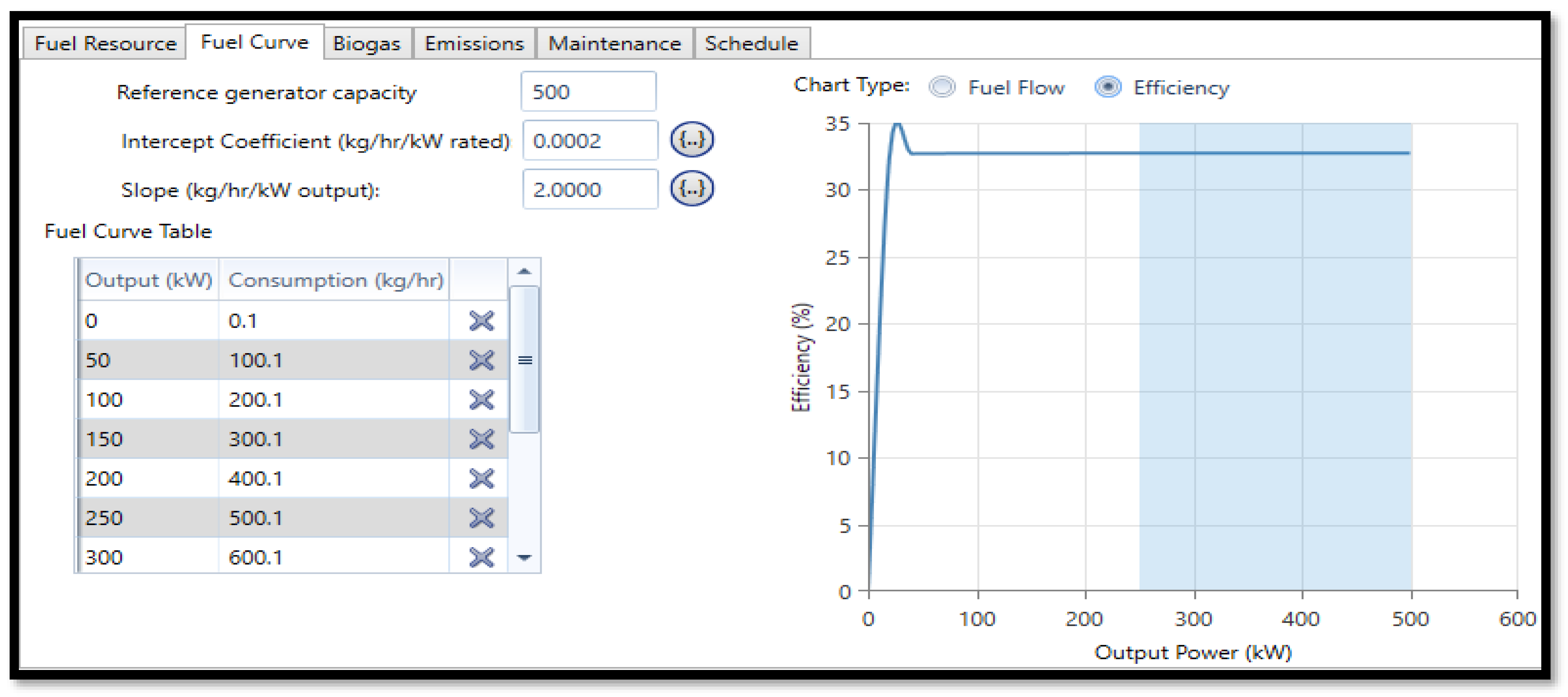
The referenced capacity of the downdraft biomass gasifier generator was 500 kW. Relating the graphical expression of the biomass (fuel) consumption rate and the biomass gasifier generator’s output power, a clear illustration explaining that as the load demand increases, output power increases steadily and the fuel consumption also increases with time was found, while the point of interception from the graph was nearly equal to zero in terms of the fuel consumption rate per generated capacity = 0.1 kg/h/kW from the linear equation expressed below.
P = 2.0X + 0.0001, where X = the output power of the biomass gasifier generator (kW), P = the biomass fuel consumption (kg/h), and the intercept represents the fuel consumption per rated capacity during the operation of the biomass generator which gives a constant value of 0.0001. As x ranges from 0 to 500 kW, P increases from 0.1 to 1000.1 kg/h which is tabulated in Table 7 below.
The efficiency–output power relationship of the biomass gasifier generator from Figure 5 was also another critical issue that was addressed in the hybrid power system unit in terms of stability (steady power production flow) and power maximization. As the output power of the biomass generator increased slightly from the starting point, its efficiency matured exponentially in increasing order alongside an increment in the generator’s speed until it approached its peak efficient value (35%) where the maximum current was drawn from the system to the load. Despite further increments in the output power, the system’s efficiency experienced a drop to 33% and hence became steady at a constant efficiency of 33% as the output power increased from 30 kW–500 kW.
The properties of the 500-kW capacity downdraft biomass gasifier were tabulated in Table 8 below, where the biogas was the acting fuel source for the generator being produced from the gasification of the available biomass resources within the isolated community of Muang Lopburi.
From the analysis in Table 9, the simulated result showed that 2.0 g/kg of carbon monoxide and 1.25 g/kg of nitrogen oxides were emitted from the biomass gasifier system. While there was no particulate matter, burnt hydrocarbons and a proportion of converted fuel sulfur were involved in the emission process with respect to the fuel properties in Table 10. The scheduled maintenance for the generator occurred after every 250 h of operation.

4.2. Integrated Island (Off Grid) Energy System Architecture

A Schneider solar PV model was used with a rated power capacity of 630 kW, a two-axis MPPT (maximum power point tracking) system alongside 20% ground reflectance, and an optimizer (dedicated inverter) of 630 kW designed to operate for 4380 h per year with 12 operational hours between the period of 7.00 a.m. and 18.00 p.m. daily based on the availability of the solar irradiation penetrating it. The biomass gasifier system kick-started when the solar PV and storage units were out of operation or deficient in power supply towards the load demand; therefore, it assisted the hybrid system to charge the batteries, storing energy into the flywheel, and energizing the AC loads effectively.
The entire network system architecture from Table 11 after optimization met the energy demand successfully without any capacity shortage or unmet electric load and thereby produced excess energy beyond the load requirement. It was discovered that the configuration of the solar-BMGs-TLC-boiler-NaS-flywheel system produced the highest amount of excess electricity (1088 kWh/yr) when compared to the other energy systems’ architectures. They (the system architectures) all possessed the same renewable fraction (93.9%) of energy distribution from renewable energy sources (solar PV and biomass generator) with a load-following control strategy in operation. Hence, the entire system configurations were technically efficient and reliable without a fossil fuel generator in support.

4.2.1. Electric Power Consumption

Figure 6 illustrated the annual electric production from the photovoltaic and biomass gasifier plants with values of 937,271 kWh/yr and 31,250 kWh/yr, the total generation was 968,521 kWh/yr, and the simulated results showed that the solar PV contributed a major (96.8%) proportion as compared to the biomass proportion (3.23%) in the renewable power generation. The annual AC load consumption consisted of electrical AC primary loads of 888,961 kWh/yr and deferrable loads (AC) of 32,863 kWh/yr while the excess electricity (67.6 kWh/yr) generated beyond the AC loads requirement was diverted to the grid system for sales; additionally, the load consumption rate (96.4%) had a dominant effect as compared to the deferrable loads (3.57%), and it produced a total energy consumption of 921,825 kWh/yr (100%) annually. The designed algorithm in line with the modeled configuration proved that the excess electricity remaining (0.007%) after the fulfillment of the energy demand was sold back to the grid system with a 93.9% fraction from the renewable sources and 1117% maximum renewable penetration. The monthly electricity production as depicted in the histogram below shows the domineering effective function of the solar PV power plant (regular operating periods) over the biomass generator (seasonal operating periods).

4.2.2. Thermal Consumption

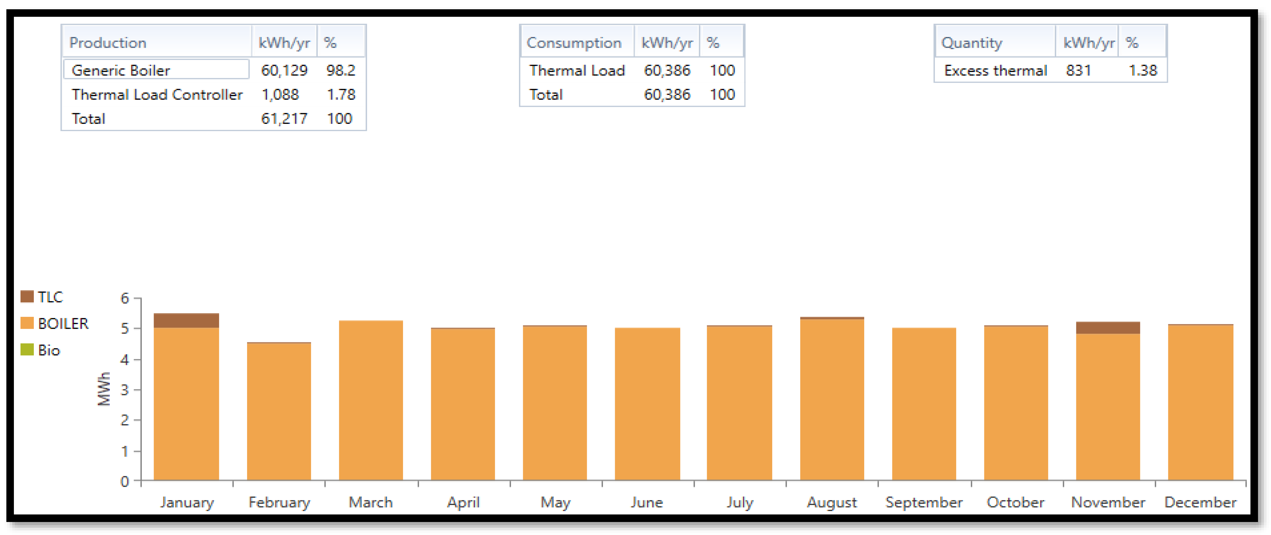
Thermal energy was generated from the TLC, boiler, and downdraft biomass gasifier plant as detailed in the simulated result from Figure 7. A discovery was made from the generic boiler (used for space heating, heat radiator, cooking, etc.) as the largest consumer of heat energy (98.20%) from the hybrid power system with a value of 60,129 kWh/yr (yearly) while the thermal load controller only generated a lower portion of energy (1088 kWh/yr, 1.78%) from the total energy (61,217 kWh/yr) generated annually. The energy consumption from the thermal load within the system was 60,386 kWh/yr, accounting for 831 kWh/yr (1.38%) of excess thermal energy annually, which is proof of a loss minimization and heat regulation within the hybrid power generation system environment.

4.2.3. Sodium–Sulfur (NaS), Iron Flow (Fe-ESS), Lithium Nickel Manganese Cobalt Oxide (Li-NMC), and Flywheel Energy Storage Units

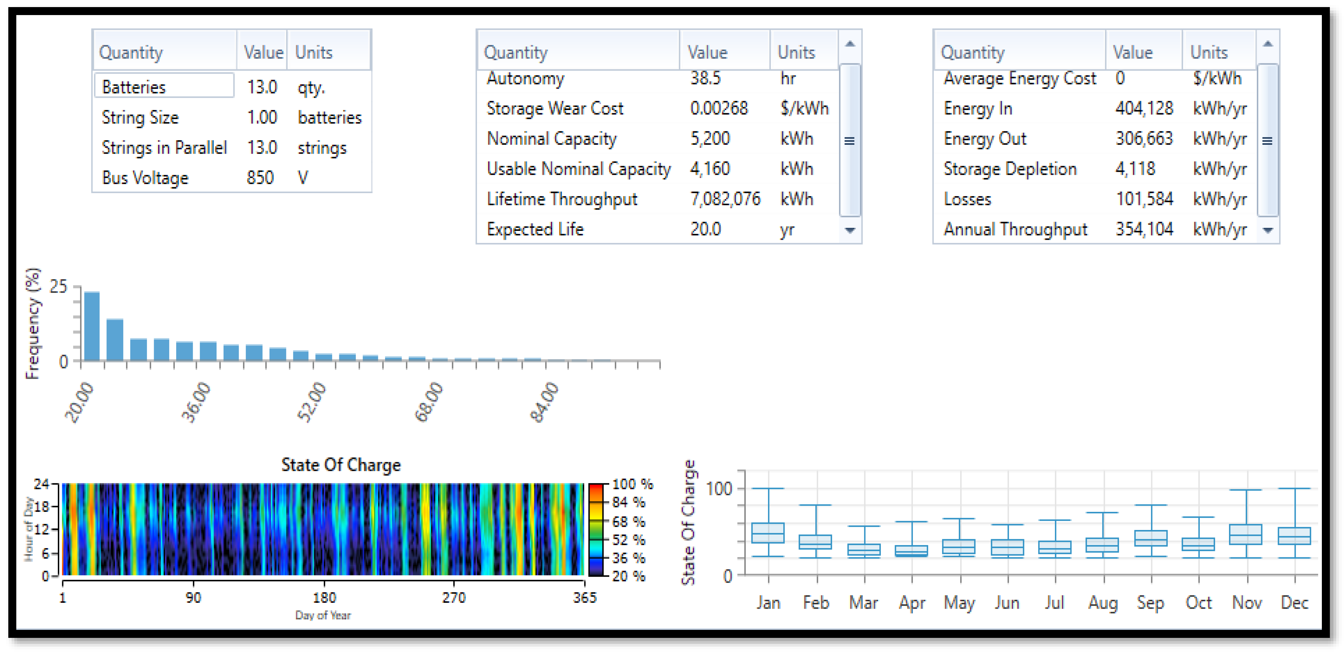
The 38.5 h autonomous iron flow–energy storage system (Fe-ESS) operation from the hybrid modeling consisted of a programmed 20% minimum state of charge and 100% initial state of charge (SOC-max) with a minimum storage life of 5 years. Its nominal designed voltage capacity was 850 V and it had an available nominal energy capacity of 5200 kWh and a usable nominal energy potential of 4160 kWh. It was made up of 13 parallel batteries in a single string where the effective voltage combination was 850 V. The effective voltage (total voltage) was fed to the direct current (DC) bus to supply the DC current to the bidirectional converter for DC to AC current conversion to power the AC loads when the generators were out of service. The simulated inflow and outflow energy of Fe-ESS was 404,128 kWh/yr and 306,663 kWh/yr within a year, which was accountable for a considerable amount of yearly energy losses (101,584 kWh/yr) in the hybrid system. The cyclic energy through the Fe-ESS bank (energy stored and delivered) in a year was measured to be 354,104 kWh/yr. The frequency and periodical usage of the iron flow battery showing its state of charge monthly relationship in a year is depicted in Figure 8. The expected life span was 20 years.
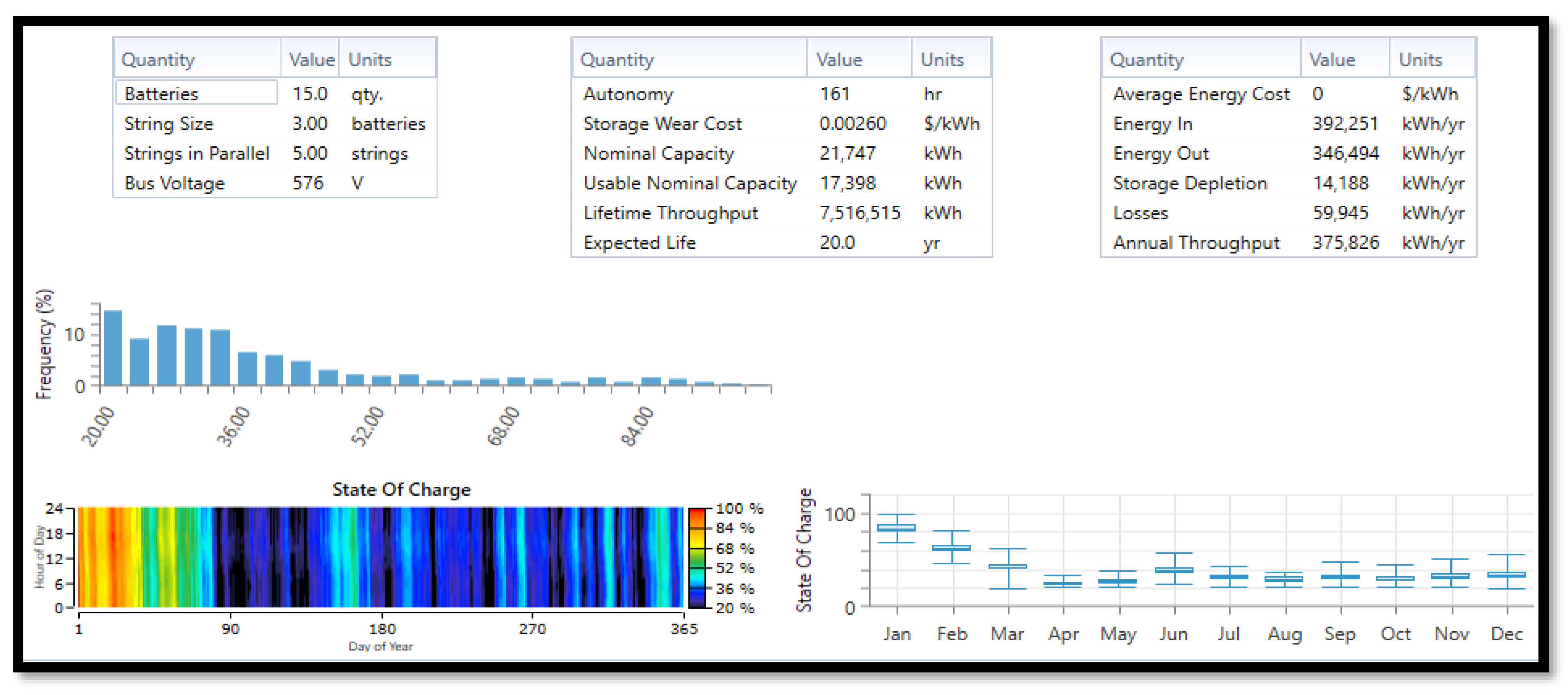
The simulation results from the sodium sulfur (NaS) battery bank indicated that it operated beyond the Fe-ESS autonomously at a rate of 161 h, it had a nominal potential capacity of 192 V with a higher nominal energy value of 21,747 kWh, and it had a usable nominal energy capacity of 17,398 kWh and thereby shared the same life span of 20 years with the Fe-ESS. However, the influx and outflux energies were 392,251 kWh/yr and 346,494 kWh/yr, respectively, with a lower loss of 59,945 kWh/yr, and the lower cyclic energy through the NaS bank (energy stored and delivered) in a year was 375,826 kWh/yr when compared to the iron flow bank (Fe-ESS). Graphically, its frequency and periodical range of operation in relation to the state of charge and monthly usage was lower in comparison to the Fe-ESS, which indicated that NaS, regardless of having the same minimum and maximum S.O.C (20% and 100%) with the iron flow, consumed less energy despite its higher efficiency (85%) than the iron flow. The sizing arrangement (NaS) was made up of nine batteries: three parallel batteries in a string forming three different strings in a series combination to one another with an effective voltage of 576 V that was supplied towards the DC bus for electricity supply to be converted by the bidirectional converter into AC energy.
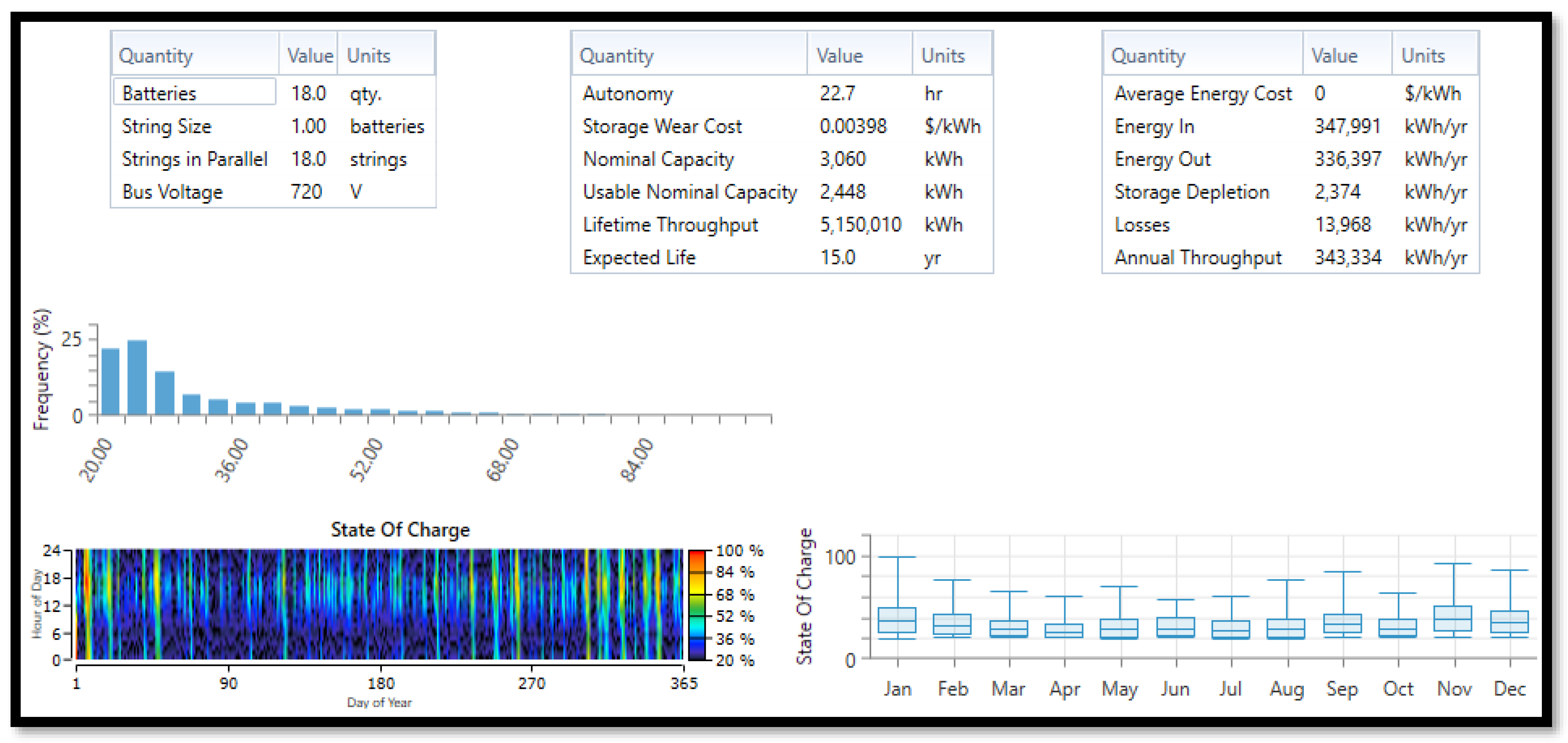
The lithium nickel manganese cobalt oxide (Li-NMC) battery possessed the least in terms of losses (13,968 kWhyr−1), an autonomous hour of operation (22.7 h), lifespan (15 years), least influx and outflux energy flows (347,991 kWh/yr and 336,397 kWh/yr), cyclic stress (energy stored and released) within a year (343,334 kWh/yr) with the lowest nominal energy capacity (3060 kWh), and a usable nominal energy capacity of 2448 kWh out of all the three batteries used in this hybrid system project. A total of 18 Li-NMC batteries were arranged in parallel with each having a nominal designed voltage capacity of 720 V in a single string, which resulted in an effective voltage of 720 V. The simulated graphical waveform depicted its minimum and maximum state of charge (20% and 100%), and its periodical operational frequency fluctuated in a decreasing order.
Further analyses were performed after obtaining the simulation results from the three batteries (Fe-ESS, NaS, and Li-NMC). It was discovered that the Li-NMC, NaS, and Fe-ESS batteries had their input energy capacities in ascending order of magnitude (347,991 kWh/yr, 392,251 kWh/yr, and 404,128 kWh/yr). During the charging process, the Fe-ESS battery tended to draw a larger current than the NaS and Li-NMC batteries while the Li-NMC battery drew the least current from the AC power plant, which indicated that the iron flow battery charged faster than the NaS battery while the NaS battery charged quicker than the lithium-NMC battery. In the discharging process, the NaS battery was the first battery to release energy towards the load demand when the power supply from the generating source of the renewable power plants was low, and as load consumption (energy demand) increased beyond the supply capacity of the NaS battery, the Li-NMC battery became the next battery to give out energy followed by the Fe-ESS battery due to their state of health; thereby, they acted in coordination (second battery) in supplying more current from the storage units to provide further support to the network system while the lower supply capacity among the batteries commenced charging (cycle charging) instantly. In terms of losses, the Li-NMC battery possessed the least energy loss followed by the NaS battery while the Fe-ESS battery had the highest form of losses with their respective cyclic charging and discharging stress in order of magnitude (Li-NMC: 343,334 kWh/yr; NaS: 375,826 kWh/yr; and Fe-ESS: 354,104 kWh/yr). The resultant annual energy (1,144,370 kWh/yr) capacity from the three batteries proved their sufficiency in energy delivery at meeting the AC loads required at their fullest without any interruption or disturbance, which can arise from deficit power of the generator sources (biomass gas plant/solar PV) and inactive operations from the grid network. The flywheel system during the simulation process had a standby power whereby it consumed a parasitic load of 12 kW that was being maintained constantly all throughout the year in the hybrid power system network modeling. Its starting power consumption of 12 kW enabled potential support (through the flywheel’s operating power reserve generation of 458 kW) in the electrical generation/cogeneration processing within the microgrid network, thereby acting as an electric motor for energy storage and a generator for energy supply when there was a shortage in capacity from the power plant sources. Its main function was to act as a spinning reserve, improving the power quality, reducing the cyclic stress towards the batteries, reducing the internal heat of the batteries, and harmonics in the power system network.
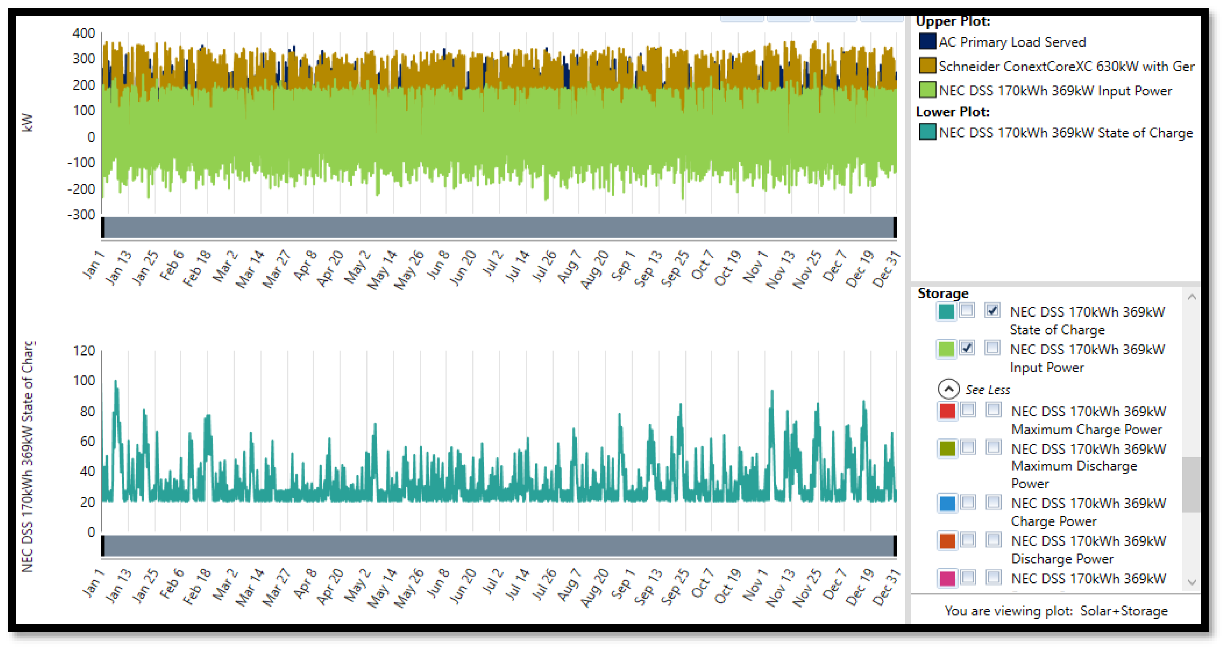
The proposed algorithm and hybrid system network configuration from Figure 1 met all the load requirements under various working conditions in the Mueang community with no shortage in capacity from the energy system’s design and incorporation of a thermal load controller to handle the thermal loads by supplying the adequate thermal energy towards it. The coordination between the AC loads, microgrid hybrid power network services to the loads, and thermal load controller in minimizing heat dissipation, as well as the appropriate allocation/utilization of power production to consumer and storage units were successfully achieved and are displayed in the simulated waveform of Figure 7.

4.2.4. Hybrid Power Grid System Network

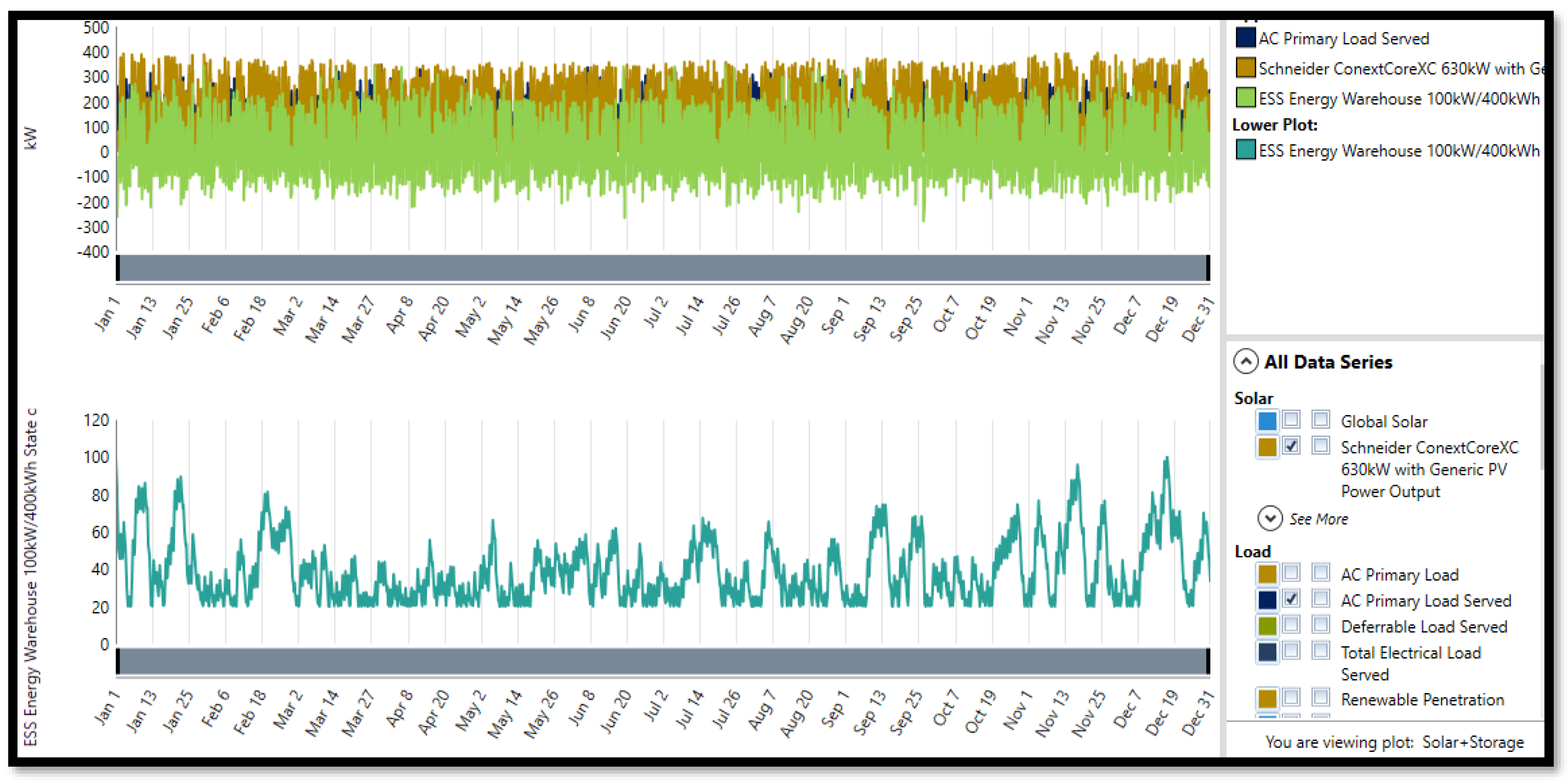
The schematics of the hybrid microgrid network from Figure 4 shows that the utility grid system was integrated into it, meaning the integrated microgrid system could sell or purchase electricity from the grid network. When the electric energy generated from the hybrid renewable power plants was beyond the load capacity at the isolated Lopburi community, it (the generated excess electricity from the community) was sold back to the grid system, but when the energy (electricity) produced from the hybrid power system of the community was below the load capacity, then the hybrid system could buy electric power from the utility grid network as illustrated from the simulated results in Figure 9, Figure 10, Figure 11, Figure 12 and Figure 13. The estimated capital cost and grid power price from the simulation HOMER power tool was USD 11,344/km and USD 0.14/kWh with operational and maintenance costs of USD 160 yr−1km−1.
In this hybrid system, the maximum grid extension distance was 100 km, and beyond this distance (extension) the hybrid network is rendered infeasible for grid connections/extensions. In this design, two control systems known as cycle charging and the load-following strategy were adopted to provide efficient energy utilization between the sending and receiving hybrid power microgrid network. The grid system was an unreliable network that could operate for a period of 24 h within the Muang Lopburi community except for impromptu circumstances where preventive and corrective maintenance were required for a period of at least 8 h depending on the gravity of the external effect on it. Hence, the grid would not be available to provide electricity to the isolated community at that period, and the stand-alone hybrid power system (solar biomass) with its storage units would commence operation immediately to avoid a power interruption or outage within the community with the help of the programmed control system across the microgrid network. The control system incorporated load-following/cycle-charging strategies. The load-following strategy is dispatched when the grid network is operated by producing enough electric power to electrify and energize the required primary AC loads in the community while the objective of lower priority (charging the battery banks, energy storage on the flywheel, and serving the deferrable AC loads) was assigned to be energized by the hybrid renewable power plants which can be ramped up to sell electricity to the grid network based on economic advantages.
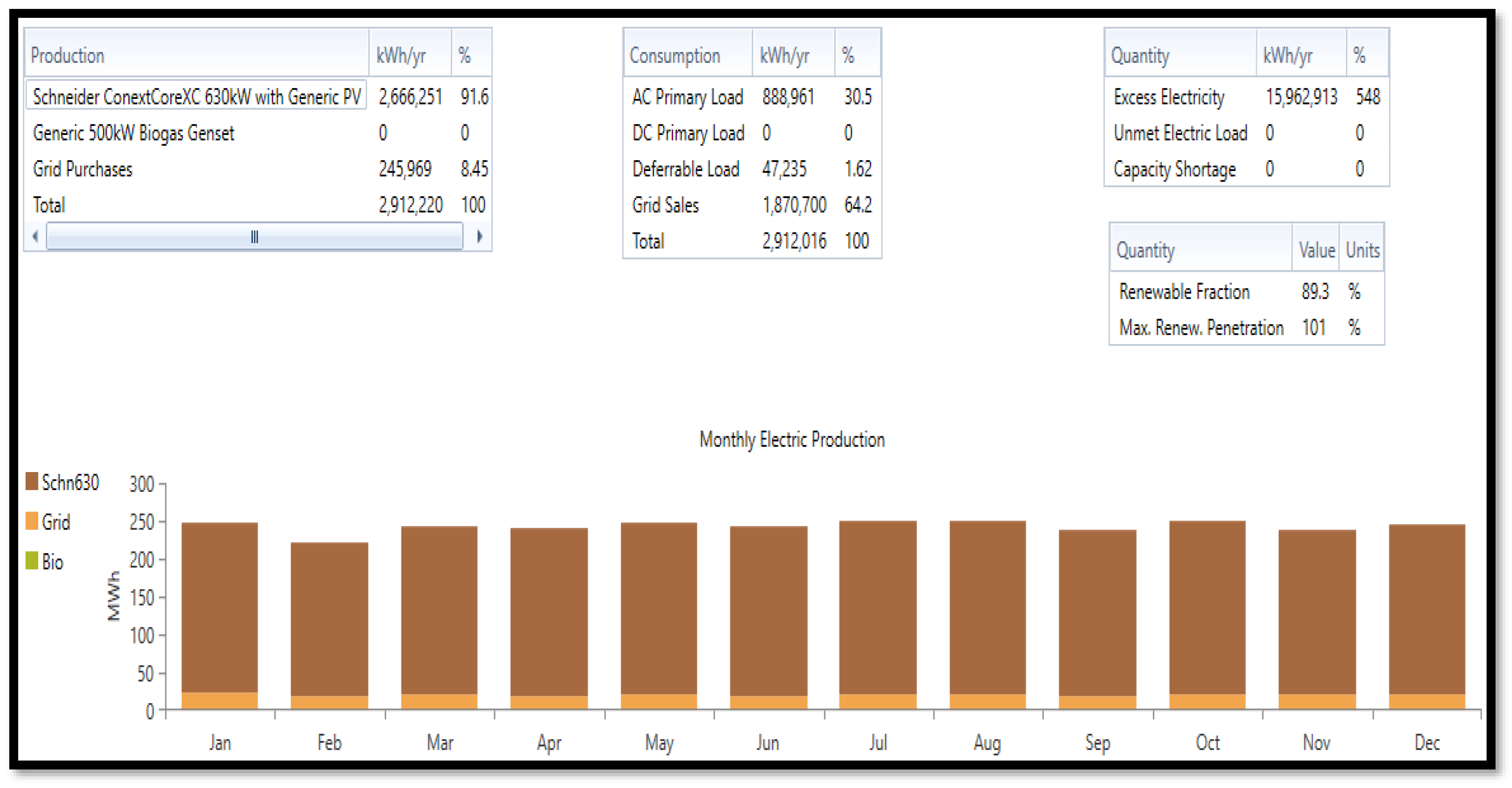
The strategy behind cycle charging is when a power generator serves electricity to the primary AC loads at a full output power operation while the excess electric power production flows to the lower priority objectives (AC deferrable loads, charging the batteries, and storing energy on the flywheel). The configuration of grid/hybrid renewable power sources/LiNMC/flywheel adopted the load-following dispatched strategy in Figure 14. When the microgrid network was in connection with the grid system, the grid/hybrid alternative power sources/Fe/flywheel system configuration adopted a dispatched cycle charging strategy from the control system in Figure 15 and the grid/hybrid renewable power sources/NaS/flywheel system adopted the load-following dispatched strategy in Figure 16, respectively. The hybrid energy systems from Figure 14 and Figure 16 produced the same percentage of excess electricity (549%) despite slight differences in their annual excess energy production (15,962,868 kWh/yr and 15,963,855 kWh/yr). It can be observed from the histogram that the solar photovoltaic plant and grid system were the major primary source of energy operating frequently while the biomass gasifier system was completely out of operation during this period as compared to the island system (off grid) configuration in Figure 6 when it was operating seasonally. The solar PV plant generated the same amount of annual energy from Figure 14, Figure 15 and Figure 16 (2,666,251 kWh/yr) in each system’s configuration at close percentage values (91.6%, 91.6%,91.7%), thereby maintaining steady annual energy sales (1,868,818 kWh/yr; 64.2%) back to the grid system, which is an indication that the solar PV plant produced more annual energy than the grid system. It can also be depicted from Figure 14, Figure 15 and Figure 16 that each hybrid energy system purchased a lesser amount of annual energy (243,877 kWh/yr, 8.38%; 245,969 kWh/yr, 8.45%; 242,871, 8.35%) from the grid system in comparison to their energy sales. Another discovery from the simulated result of the grid-connected systems (Figure 14, Figure 15 and Figure 16) highlighted their renewable fraction (89.4%, 89.3%, and 89.4%) to be lesser in value than the island (off grid) configuration operational system whose renewable fraction was of a constant value (93.9%) from Table 11 in all the energy system’s configuration design.

Breakeven Distance and Grid Extension

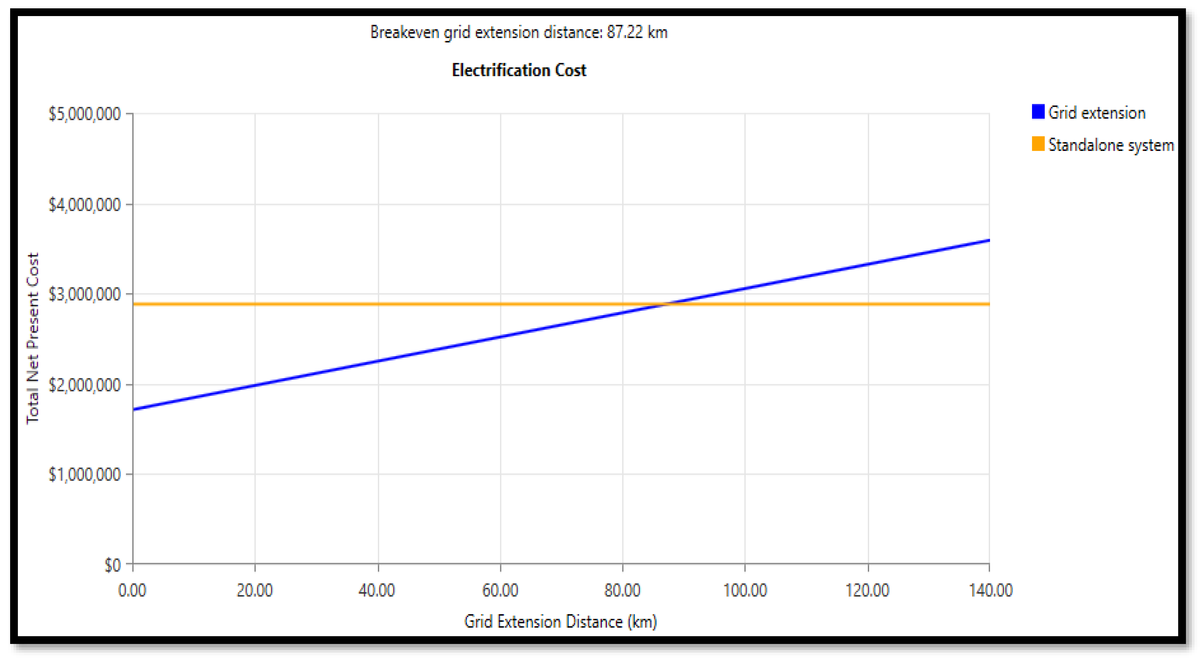
The importance of the breakeven distance and grid extension in accessing electricity towards the unelectrified isolated community in Lopburi shown in Figure 4 is inevitable when comparing the choices between the grid extension connected–conventional system and off-grid (standalone) hybrid power renewable system. The meeting point between the grid extension–conventional system and standalone (independent) hybrid power system gives the breakeven grid extension distance when the total net present cost (measured in dollars) is plotted against the grid extension distance (measured in km) graphically. The total net present cost for the standalone/island (off grid) hybrid power system’s connection is a function of its potential capacity in meeting up the energy demand in the province, while the TNPC (total net present cost) for the grid extension conventional system relied primarily on the path length between the grid point of existence and extension from the grid. The cost of installing grid lines, the loss in the transmission lines due to distance, the operational and maintenance costs allotted yearly, the availability of infrastructural facilities for the network system, and the electrical cost due to the electrical power demand from the Lopburi community affected the TNPC.
The standalone system represents the hybrid (solar–biomass) renewable power network that was independent of the grid network, an autonomous power system (off-grid connection) to the community at a fixed (constant) value of the total net present cost (USD 2,883,070) spread all through the simulated graph plot, denoted by the orange horizontal straight line from Figure 17 after optimizing the designed system configuration. The grid extension line in blue illustrates the linear relationship between the microgrid network system (connection of the grid to the hybrid renewable energy network) and TNPC. As the extension in the grid distance increased, the total net present cost value also increased linearly across the graph, which means that as the load demand varied, the extension in the grid distance varied proportionately. Hence, TNPC was proportional to the microgrid component capacity network configuration. The meeting point (interception) between the grid extension and standalone system yielded a breakeven grid extension distance of 87.22 km, which demonstrates that if the community of Lopburi province was beyond the extension distance value of 87.22 km, a grid connection would not be feasible for the hybrid renewable power system (as it would operate autonomously to power the isolated community). The cost involved with the grid extension distance had no correlation with the load demand. As the energy demand increased, the breakeven grid extension distance was reduced and vice versa.

4.2.5. Bidirectional Converter (GTP519S)

The bidirectional converter model for the microgrid hybrid power network was Leonics GTP519S with a capacity rating of 900 kW, 700 V D.C acting as a rectifier and inverter system depending on the type of current sources generated from the hybrid power plants that are fed into it. The grid network was connected to the bidirectional converter for the purpose of supplying electric charges to the storage units (batteries/flywheel) through the rectification mode process (conversion of AC to DC) while the storage units supplied DC energy to the converter through the inversion mode process (conversion of DC to AC) to be fed to the AC loads/deferrable loads during a deficiency in power from the generating sources. Such a bidirectional converter was a grid-following, large-scaled hybrid power system acting as an intermediary between the AC and DC power sources within the community. The energy system’s behavioral response towards the grid system, hybrid renewable power sources, and storage units was further proof of the influx and outflux of energy production through it.

4.2.6. Microgrid Hybrid Renewable Energy System Impact on Greenhouse Gas Emissions

The downdraft biomass gasifier system utilizes combustion reaction processing to release CO2 (carbon dioxide) emissions for electric current production. The CO2 emissions are carbon dioxide neutral, which is inconsiderate for increments in the emissions of GHGS to the atmospheric environment due to CO2 removal from the atmosphere by the action of plants as a component of the world’s natural carbon cycle. The biomass resources, if not utilized in time to produce electricity, undergo decomposition and thereby emit CO2 into the atmosphere. The solar photovoltaic system does not emit any greenhouse gases (GHGS) because of its carbon-free energy source (fuel); hence, emissions from GHGS to the atmospheric environment can only undergo reduction when the conventional power plants (fossil fuel generators) are out of place. Fossil fuels (coal, oil, gas) have contained locked-up carbon for many centuries, and when they are used for electricity production, the locked-away CO2 within it (the fossil fuels) is added to the atmosphere. The biomass gasifier application as an energy generation source reduces the fossil-based CO2 amount being emitted to the environment by the action of fossil fuel displacement.
The data in Table 12 are the various emission levels of GHGS produced from the optimized microgrid hybrid renewable power system network in accordance with its configuration due to the biodiesel fuel source of the thermal load controller boiler system. The optimized architectural configuration of solar PV/biomass gas/converter/TLC/Li-NMC/flywheel produced the highest emission value of 19,269 kg/yr CO2, 1.91 kg/yr of CO, and 1.20 kg/yr of NOX gases annually while the configuration of solar PV/biomass gas/converter/TLC/NaS/flywheel produced the lowest emission value of CO2: 19,045 kg/yr, the lowest value of CO: 0.260 kg/yr, and the lowest value of NOX: 0.163 kg/yr, with both configurations having closer values of 47.3 and 47.2 kg/yr of SO2 gases emitted annually. No gases from particulate matter and unburnt hydrocarbon were evolved in the entire architectural designed hybrid system during their annual operation. The values of 19,193 kg/yr CO2, 1.03 kg/yr CO, and 0.643 kg/yr of NOX had the highest content of 47.4 kg/yr SO2 gases that were emitted annually from the solar PV/biomass gas/converter/TLC/Fe-ESS/flywheel configuration. The obtained simulated data has proven that the hybrid microgrid/energy storage unit is superior to conventional-only (fossil fuel) energy-generated systems in terms of minimizing environmental pollution, efficiency maximization, and availability. On the contrary, the grid-connected network produced a massive emission of polluted gases (155,452 kgyr−1, 153,495 kgyr−1, and 154,130 kgyr−1 of CO2; 674, 665, and 668 kgyr−1 of SO2; 330, 325, and 327 kgyr−1 of NOX) from each architectural design annually, thereby causing a heat trap from the greenhouse gases and making the community warmer due to fossil fuel generators from the grid network as compared against the standalone (off grid) hybrid power network with low emissions and a clean energy mechanism.
The electromechanical storage device (flywheel) operated as a generator (power supply) and an electric motor (energy storage) at the same time within the hybrid energy network. It improved power quality transmission and resolved harmonics issues from nonlinear loads by minimizing energy losses. The flywheel integration of the energy system architectures from Figure 14, Figure 15 and Figure 16 explained a drop in their excess production of electricity (549%, 548%, and 549%), and their renewable penetration dropped (89.4%, 89.3%, and 89.4%) with uniform grid sales (64.2%) and an average grid purchase of 8.39% when compared to the energy system architectures that were disengaged from the flywheel system in Table 13. It was observed that the excess production of electricity increased (570%) with their renewable penetration (91.4%); additionally, the grid sales experienced an increment (67.3%) while the average grid purchase experienced a drop (6.67%) in value. Hence, the FESS supported the entire energy network in power production and minimized energy loss.
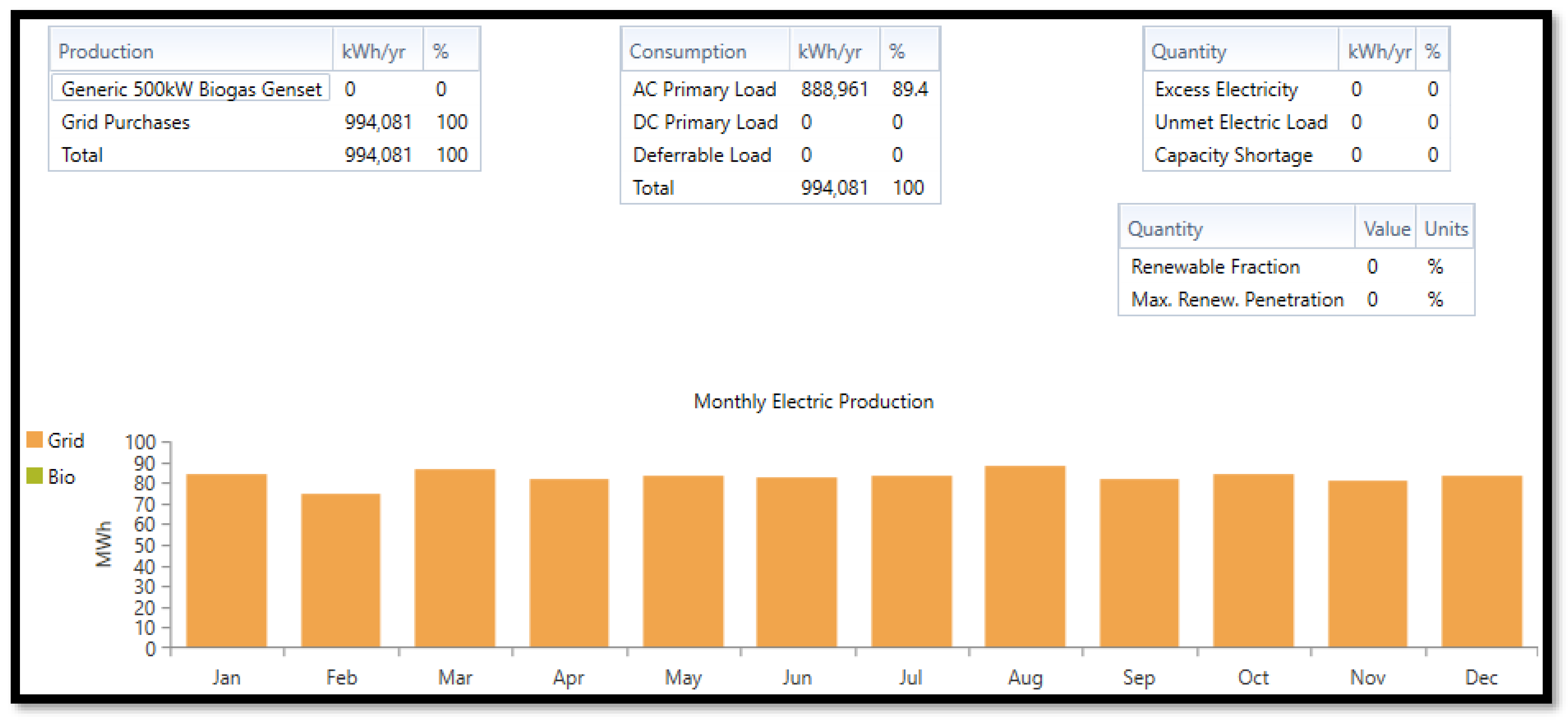
The simulated results obtained from the island-able mode of the hybrid energy network from Figure 18 completely described the isolation ability of the microgrid network from the grid system despite the grid connection mode of the integrated energy system architecture. This was an indication of no renewable penetration (solar PV and biomass generators are completely disconnected from the entire network), no excess energy production available, no energy storage system in activity, and the absence of storage loads (deferrable load). The grid system was solely responsible for the entire annual energy generation (994,081 kWh/yr) towards the load (888,961 kWh/yr) under this critical condition of operation as the flywheel stored the deficit energy consumption (105,120 kWh/yr, 10.6%) through the cycle charging strategy to avoid stability issues that might have interrupted the normal operation of the entire energy network. The entire annual energy was purchased from the grid system with no energy sales in return towards the grid network.

5. Conclusions

The simulated results in Table 11 show that the off-grid architecture of the solar/BMGs/TLC-boiler/NaS/flywheel energy system was the highest producer of excess annual electric energy (1088 kWh/yr) under the load-following control strategy compared to the other system architectures despite their constant fraction of renewable penetration (93.9%). The annual energy production (968,521 kWh/yr) from the independent hybrid alternative energy sources (solar and biomass plants) met beyond the annual energy demand (921,825 kWh/yr) with an excess annual electric energy production of 67.6 kWh/yr without grid system interference, which demonstrated a high penetration of renewable fractions (93.9%). The grid-connected (microgrid) network in Figure 14, Figure 15 and Figure 16 could reduce the energy production burden from the hybrid alternative energy sources (91.6%, 91.7% of renewable energy production, and 8.45% of grid energy production) and thereby contribute towards the increment in the excess annual energy production (549%) for energy storage, deferrable load, and grid sales consumption. The solar/BMGs/Fe/flywheel/grid configuration in Figure 15 adopted a cycle-charging strategy against other grid-connected architectures that adopted the load-following strategy. When the power sources (solar and biomass gasifier) of the network were operating below capacity, the potentials of the energy storage systems (Li, Fe, NaS) produced a resultant annual energy of 1,144,370 kWh/yr as shown in Figure 8, Figure 10, and Figure 12, which was beyond the annual energy demand (921,825 kWh/yr) as a measure of their sufficiency against power interruptions, power outages, and maintaining power stability between the energy sources and load (energy demand). The enablement of the thermal load controller was to regulate (limit) the excess energy that the load could draw from the hybrid energy sources and supply it (the regulated excess energy consumption) to the thermal bus in serving the load to the fullest capacity. The annual thermal energy production shared between the boiler system (60,129 kWh/yr; 98.2%) and thermal load controller (1088 kWh/yr; 1.78%) in Figure 7 demonstrated the potential of TLC to limit the excess heat (thermal) energy from the electric production of the hybrid power sources (grid and solar) to 1088 kWh/yr or 1.38%, and the temperature would be suitable enough to have a positive effect on the building structures of the community. The flywheel operated as a generator in feeding the load during the grid connection mode by reducing the excess electric energy production and renewable penetration. It (the flywheel) operated as a motor by assisting in charging the batteries, increasing the grid purchase, and reducing the grid sales, as shown in Table 13 and Figure 14, Figure 15 and Figure 16. The island-able nature of the microgrid-network-adopted cycle-charging strategy from the grid system (annual energy source of 994,081 kWh/yr) operated as the only source of energy production when the other energy sources (solar, biomass, batteries) were completely isolated from the grid mode during this operation. The primary load and flywheel system consumed the entire energy production from the grid network and have satisfied the load and capacity shortage requirement without excess energy left.
The above modeled and simulated integrated solar photovoltaic plant/downdraft biomass gasifier/energy storage system for an isolated (Lopburi) community in Thailand was shown to operate effectively under grid-connection mode, island-able mode (connected to the grid and acting in an isolated manner), and island mode (completely independent from the grid system) through the adoption of novel multioptimization energy assessment/power management control algorithms with a control system (load following, combined dispatch, and cycle charging) strategy and the application of the HOMER PRO microgrid analysis tool for the architectural energy network.

Author Contributions

Conceptualization, B.P. (Boonrit Prasartkaew); methodology, O.O.A.; software, O.O.A.; validation, B.P. (Boonyang Plangklang) and B.P. (Boonrit Prasartkaew); formal analysis, B.P. (Boonyang Plangklang) and O.O.A.; writing—original draft preparation, O.O.A.; review and editing, B.P. (Boonyang Plangklang) and T.S.A.; visualization, O.O.A. and T.S.A.; supervision, B.P. (Boonyang Plangklang) and B.P. (Boonrit Prasartkaew); investigation, O.O.A.; resources, B.P. (Boonyang Plangklang) and B.P. (Boonrit Prasartkaew). All authors have read and agreed to the published version of the manuscript.

Funding

This research paper was sponsored by the E-CUBE-I RMUTT scholarship towards the Department of Energy and Materials Engineering program at the Faculty of Engineering, Rajamangala University of Technology Thanyaburi, Thailand with no external funding attached to it.

Data Availability Statement

The data acquisition was obtained from biomass database potential in Thailand, global solar atlas database potential, renewable energy outlook in Thailand, IEEE explore library (scholarly articles) source, and hybrid optimization modeling of electric renewable (HOMER) professional (Pro) microgrid analysis power tool software.

Acknowledgments

The authors express their deep gratitude towards the NSRF from the Program Management Unit of Human Resources and Institutional Development Research and Innovation [BIBF660068].

Conflicts of Interest

The authors declared no conflict of interest in this research paper.

References

  1. Renewable Energy Agency. Thailand Renewable Energy Outlook Based on Renewables Readiness Assessment and Remap Analysis; Renewable Energy Agency: Masdar City, United Arab Emirates, 2017. [Google Scholar]
  2. Che, L.; Zhang, X.; Shahidehpour, M.; Alabdulwahab, A.; Abusorrah, A. Optimal interconnection planning of community microgrids with renewable energy sources. IEEE Trans. Smart Grid 2017, 8, 1054–1063. [Google Scholar] [CrossRef]
  3. Lv, T.; Ai, Q. Interactive energy management of networked microgrids-based active distribution system considering large-scale integration of renewable energy resources. Appl. Energy 2016, 163, 408–422. [Google Scholar] [CrossRef]
  4. Jung, J.; Villaran, M. Optimal planning and design of hybrid renewable energy systems for microgrids. Renew. Sustain. Energy Rev. 2017, 75, 180–191. [Google Scholar] [CrossRef]
  5. Khalid, M.; Ahmadi, A.; Savkin, A.V.; Agelidis, V.G. Minimizing the energy cost for microgrids integrated with renewable energy resources and conventional generation using controlled battery energy storage. Renew. Energy 2016, 97, 646–655. [Google Scholar] [CrossRef]
  6. Qamar, A.; Iqbal, J.; Saher, S.; Shah, A.A.; Basit, A. Design of optimized energy system based on active energy-saving technologies in very low-energy smart buildings. Trans. Emerg. Telecommun. Technol. 2022, 33, e3691. [Google Scholar] [CrossRef]
  7. Patel, A.M.; Singal, S.K. Optimal component selection of integrated renewable energy system for power generation in stand-alone applications. Energy 2019, 175, 481–504. [Google Scholar] [CrossRef]
  8. Ramesh, M.; Saini, R.P. Dispatch strategies based performance analysis of a hybrid renewable energy system for a remote rural area in India. J. Clean. Prod. 2020, 259, 120697. [Google Scholar] [CrossRef]
  9. Upadhyay, S.; Sharma, M. Selection of a suitable energy management strategy for a hybrid energy system in a remote rural area of India. Energy 2016, 94, 352–366. [Google Scholar] [CrossRef]
  10. Rajanna, S.; Saini, R. Modeling of integrated renewable energy system for electrification of a remote area in India. Renew. Energy 2016, 90, 175–187. [Google Scholar] [CrossRef]
  11. Bhatt, A.; Sharma, M.; Saini, R. Feasibility and sensitivity analysis of an off-grid micro hydro–photovoltaic–biomass and biogas–diesel–battery hybrid energy system for a remote area in Uttarakhand state, India. Renew. Sustain. Energy Rev. 2016, 61, 53–69. [Google Scholar] [CrossRef]
  12. Shezan, S.; Julai, S.; Kibria, M.; Ullah, K.; Saidur, R.; Chong, W.; Akikur, R. Performance analysis of an off-grid wind-PV (photovoltaic)-diesel-battery hybrid energy system feasible for remote areas. J. Clean. Prod. 2016, 125, 121–132. [Google Scholar] [CrossRef]
  13. Durlinger, B.; Reinders, A.; Toxopeus, M. A comparative life cycle analysis of low power PV lighting products for rural areas in South East Asia. Renew. Energy 2012, 41, 96–104. [Google Scholar] [CrossRef]
  14. Lao, C.; Chungpaibulpatana, S. Techno-economic analysis of hybrid system for rural electrification in Cambodia. Energy Procedia 2017, 138, 524–529. [Google Scholar] [CrossRef]
  15. Rodríguez-Gallegos, C.D.; Gandhi, O.; Bieri, M.; Reindl, T.; Panda, S. A diesel replacement strategy for off-grid systems based on progressive introduction of PV and batteries: An Indonesian case study. Appl. Energy 2018, 229, 1218–1232. [Google Scholar] [CrossRef]
  16. Kim, H.; Jung, T.Y. Independent solar photovoltaic with Energy Storage Systems (ESS) for rural electrification in Myanmar. Renew. Sustain. Energy Rev. 2018, 82, 1187–1194. [Google Scholar] [CrossRef]
  17. Kohsri, S.; Meechai, A.; Prapainainar, C.; Narataruksa, P.; Hunpinyo, P.; Sin, G. Design and preliminary operation of a hybrid syngas/solar PV/battery power system for off-grid applications: A case study in Thailand. Chem. Eng. Res. Des. 2018, 131, 346–361. [Google Scholar] [CrossRef] [Green Version]
  18. Lozano, L.; Querikiol, E.M.; Abundo, M.L.S.; Bellotindos, L.M. Techno-economic analysis of a cost-effective power generation system for off-grid island communities: A case study of Gilutongan Island, Cordova, Cebu, Philippines. Renew. Energy 2019, 140, 905–911. [Google Scholar] [CrossRef]
  19. Moretti, L.; Astolfi, M.; Vergara, C.; Macchi, E.; Pérez-Arriaga, J.I.; Manzolini, G. A design and dispatch optimization algorithm based on mixed integer linear programming for rural electrification. Appl. Energy 2018, 233–234, 1104–1121. [Google Scholar] [CrossRef]
  20. Ciez, R.E.; Whitacre, J. Comparative techno-economic analysis of hybrid micro-grid systems utilizing different battery types. Energy Convers. Manag. 2016, 112, 435–444. [Google Scholar] [CrossRef] [Green Version]
  21. Merei, G.; Berger, C.; Sauer, D.U. Optimization of an off-grid hybrid PV–Wind–Diesel system with different battery technologies using genetic algorithm. Sol. Energy 2013, 97, 460–473. [Google Scholar] [CrossRef]
  22. Moretti, L.; Polimeni, S.; Meraldi, L.; Raboni, P.; Leva, S.; Manzolini, G. Assessing the impact of a two-layer predictive dispatch algorithm on design and operation of offgrid hybrid microgrids. Renew. Energy 2019, 143, 1439–1453. [Google Scholar] [CrossRef]
  23. Kaabeche, A.; Bakelli, Y. Renewable hybrid system size optimization considering various electrochemical energy storage technologies. Energy Convers. Manag. 2019, 193, 162–175. [Google Scholar] [CrossRef]
  24. Paul, S.; Schirmer, T.; Kairies, K.; Axelsen, H.; Uwe, D. Comparison of o ff -grid power supply systems using lead-acid and lithium-ion batteries. Sol. Energy 2018, 162, 140–152. [Google Scholar] [CrossRef]
  25. Luo, F.; Meng, K.; Dong, Z.Y.; Zheng, Y.; Chen, Y.; Wong, K.P. Coordinated operational planning for wind farm with battery energy storage system. IEEE Trans. Sustain. Energy 2015, 6, 253–262. [Google Scholar] [CrossRef] [Green Version]
  26. Dreidy, M.; Mokhlis, H.; Mekhilef, S. Inertia response and frequency control techniques for renewable energy sources: A review. Renew. Sustain. Energy Rev. 2017, 69, 144–155. [Google Scholar] [CrossRef]
  27. Arcos-Aviles, D.; Pascual, J.; Marroyo, L.; Sanchis, P.; Guinjoan, F. Fuzzy logic-based energy management system design for residential grid-connected microgrids. IEEE Trans. Smart Grid 2018, 9, 530–543. [Google Scholar] [CrossRef] [Green Version]
  28. Koller, M.; Borsche, T.; Ulbig, A.; Andersson, G. Review of grid applications with the Zurich 1 MWbattery energy storage system. Electr Power Syst. Re.s 2015, 120, 128–135. [Google Scholar] [CrossRef]
  29. Huang, W.; Qahouq, J.A.A. Energy sharing control scheme for state-of-charge balancing of distributed battery energy storage system. IEEE Trans. Ind. Electron. 2015, 62, 2764–2776. [Google Scholar] [CrossRef]
  30. Oudalov, A.; Cherkaoui, R.; Beguin, A. Sizing and optimal operation of battery energy storage system for peak shaving application. In Proceedings of the 2007 IEEE Lausanne POWERTECH, Lausanne, Switzerland, 1–5 July 2007; pp. 621–625. [Google Scholar] [CrossRef]
  31. Nazaripouya, H.; Wang, Y.; Chu, P.; Pota, H.R.; Gadh, R. Optimal sizing and placement of battery energy storage in distribution system based on solar size for voltage regulation. In Proceedings of the IEEE Power and Energy Society General Meeting, Denver, CO, USA, 26–30 July 2015; Volume 2015. [Google Scholar] [CrossRef]
  32. Wang, X.; Yue, M.; Muljadi, E. PV generation enhancement with a virtual inertia emulator to provide inertial response to the grid. In Proceedings of the 2014 IEEE Energy Conversion Congress and Exposition, ECCE 2014, Pittsburgh, PA, USA, 14–18 September 2014; pp. 17–23. [Google Scholar] [CrossRef]
  33. Hemmati, R. Technical and economic analysis of home energy management system incorporating small-scale wind turbine and battery energy storage system. J. Clean. Prod. 2017, 159, 106–118. [Google Scholar] [CrossRef]
  34. Zakeri, B.; Syri, S. Electrical energy storage systems: A comparative life cycle cost analysis. Renew. Sustain. Energy Rev. 2015, 42, 569–596. [Google Scholar] [CrossRef]
  35. Staffell, I.; Scamman, D.; Velazquez Abad, A.; Balcombe, P.; Dodds, P.E.; Ekins, P.; Shah, N.; Ward, K.R. The role of hydrogen and fuel cells in the global energy system. Energy Environ. Sci. 2019, 12, 463–491. [Google Scholar] [CrossRef] [Green Version]
  36. Chen, Z.; Mi, C.; Fu, Y.; Xu, J.; Gong, X. Online battery state of health estimation based on Genetic Algorithm for electric and hybrid vehicle applications. J. Power Sources 2013, 240, 184–192. [Google Scholar] [CrossRef]
  37. Kim, T.; Song, W.; Son, D.Y.; Ono, L.K.; Qi, Y. Lithium-ion batteries: Outlook on present, future, and hybridized technologies. J. Mater. Chem. 2019, 7, 2942–2964. [Google Scholar] [CrossRef]
  38. Zhang, W.; Liu, Y.; Guo, Z. Approaching high-performance potassium-ion batteries via advanced design strategies and engineering. Sci. Adv. 2019, 5, eaav7412. [Google Scholar] [CrossRef] [Green Version]
  39. Famprikis, T.; Canepa, P.; Dawson, J.A.; Islam, M.S.; Masquelier, C. Fundamentals of inorganic solid-state electrolytes for batteries. Nat. Mater. 2019, 18, 1278–1291. [Google Scholar] [CrossRef]
  40. Tan, K.M.; Babu, T.S.; Ramachandaramurthy, V.K.; Kasinathan, P.; Solanki, S.G.; Raveendran, S.K. Empowering smart grid: A comprehensive review of energy storage technology and application with renewable energy integration. J. Energy Storage 2021, 39, 102591. [Google Scholar] [CrossRef]
  41. Wei, Q.; Shi, G.; Song, R.; Liu, Y. Adaptive Dynamic Programming-Based Optimal Control Scheme for Energy Storage Systems with Solar Renewable Energy. IEEE Trans. Ind. Electron. 2017, 64, 5468–5478. [Google Scholar] [CrossRef]
  42. Xu, Y.; Zhang, W.; Hug, G.; Kar, S.; Li, Z. Cooperative Control of Distributed Energy Storage Systems in a Microgrid. IEEE Trans. Smart Grid 2014, 6, 238–248. [Google Scholar] [CrossRef]
  43. Morstyn, T.; Hredzak, B.; Agelidis, V.G. Control strategies for microgrids with distributed energy storage systems: An overview. IEEE Trans. Smart Grid 2018, 9, 3652–3666. [Google Scholar] [CrossRef] [Green Version]
  44. Lawder, M.T.; Suthar, B.; Northrop, P.W.C.; Sumitava, D.; Hoff, C.M.; Leitermann, O.; Crow, M.L.; Santhanagopalan, S.; Subramanian, V.R. Battery Energy Storage System (BESS) and Battery Management System (BMS) for Grid-Scale Applications. Proc. IEEE 2014, 102, 1014–1030. [Google Scholar] [CrossRef]
  45. Bruce, P.G.; Freunberger, S.A.; Hardwick, L.J.; Tarascon, J.M. LigO2 and LigS batteries with high energy storage. Nat. Mater. 2012, 11, 19–29. [Google Scholar] [CrossRef] [PubMed]
  46. Muzaffar, A.; Ahamed, M.B.; Deshmukh, K.; Thirumalai, J. A review on recent advances in hybrid supercapacitors: Design, fabrication and applications. Renew. Sustain. Energy Rev. 2019, 101, 123–145. [Google Scholar] [CrossRef]
  47. Poonam, K.; Sharma, A.A.; Tripathi, S.K. Review of supercapacitors: Materials and devices. J. Energy Storage 2019, 21, 801–825. [Google Scholar] [CrossRef]
  48. Dunn, B.; Kamath, H.; Tarascon, J.M. Electrical energy storage for the grid: A battery of choices. Science (80-) 2011, 334, 928–935. [Google Scholar] [CrossRef] [Green Version]
  49. Kumar, P.P.; Saini, R.P. Optimization of an off-grid integrated hybrid renewable energy system with different battery technologies for rural electrification in India. J. Energy Storage 2020, 32, 101912. [Google Scholar] [CrossRef]
  50. Global Solar Atlas. Global Solar Atlas 2.0, a Free, Web-Based Application is Developed and Operated by the Company Solargis sro on behalf of the World Bank Group, Utilizing Solargis Data, With Funding Provided by the Energy Sector Management Assistance Program (ESMAP). 2022. Available online: https://globalsolaratlas.info/ (accessed on 25 November 2022).
  51. Ali, A.Y.; Basit, A.; Ahmad, T.; Qamar, A.; Iqbal, J. Optimizing coordinated control of distributed energy storage system in microgrid to improve battery life. Comput. Electr. Eng. 2020, 86, 106741. [Google Scholar] [CrossRef]
  52. Mokhtara, C.; Negrou, B.; Settou, N.; Settou, B.; Samy, M.M. Design optimization of off-grid Hybrid Renewable Energy Systems considering the effects of building energy performance and climate change: Case study of Algeria. Energy 2020, 219, 119605. [Google Scholar] [CrossRef]
  53. Olivier, J.C.; Bernard, N.; Trieste, S.; Bourguet, S.; Aranguren, L.M.; Ireena, L. Techno-economic Optimization of Flywheel Storage System in transportation. In Proceedings of the Symposium de Génie Électrique 2014, Cachan, France, July 2014; pp. 8–10. [Google Scholar]
Figure 1. Flow chart of the power stability algorithm with its operational command.
Energies 16 05122 g001
Figure 2. Biodiversity of resources in Muang Lopburi [50].
Energies 16 05122 g002
Figure 3. Annual biomass resources and diversification.
Energies 16 05122 g003
Figure 4. Schematics of hybrid energy control system network.
Energies 16 05122 g004
Figure 5. The graph of efficiency against output power.
Energies 16 05122 g005
Figure 6. Electricity production from solar–biomass hybrid system.
Energies 16 05122 g006
Figure 7. Thermal energy consumption in the hybrid network.
Energies 16 05122 g007
Figure 8. Energy flow, sizing, and operational period of Fe—ESS battery.
Energies 16 05122 g008
Figure 9. Output power waveform of solar PV and Fe—ESS flow.
Energies 16 05122 g009
Figure 10. Energy flow, sizing, and operational period of NaS battery.
Energies 16 05122 g010
Figure 11. Output power waveform of solar PV and NaS battery.
Energies 16 05122 g011
Figure 12. Energy flow, sizing, and operational period of Li—NMC battery.
Energies 16 05122 g012
Figure 13. Output power waveform of solar PV and Li—NMC battery.
Energies 16 05122 g013
Figure 14. Grid/hybrid power system/Li-NMC/flywheel configuration.
Energies 16 05122 g014
Figure 15. Grid/hybrid power/Fe-ESS/flywheel configuration.
Energies 16 05122 g015
Figure 16. Grid/hybrid power/NaS/flywheel configuration.
Energies 16 05122 g016
Figure 17. Graph illustrating total net present cost against grid extension distance.
Energies 16 05122 g017
Figure 18. Island-able mode of the energy system architecture.
Energies 16 05122 g018
Table 1. Properties of the batteries.
BatteriesNominal
Voltage
Rating (V)
Nominal
Capacity Rating (kWh)
Nominal
Capacity Rating (Ah)
Round-Trip
Efficiency (%)
Maximum Charge
Current
Rating (A)
Maximum
Discharge Current Rating (A)
Sodium Sulfur (NaS)1921450755085.012001410
Iron flow (Fe-ESS)85040047175.0157118
Lithium-NMC72017023696.0628628
Table 2. Solar GHI and temperature [50].
MonthMonthly Mean Solar Global Horizontal Irradiance (GHI) DataDaily Temperature
(°C)
Clearness-IndexRadiation per Day (kWh/m2/dy)
January0.57705.810026.640
February0.57705.990027.200
March0.55005.780027.580
April0.56105.720027.570
May0.58805.680027.020
June0.62305.800025.160
July0.62105.860023.940
August0.59205.870023.840
September0.57405.930024.520
October0.58706.080025.430
November0.58105.860026.140
December0.58105.760026.310
Yearly Average (kWh/m2/dy): 5.8500Yearly Average (°C): 25.950
Table 3. Residential loads.
Residential EnvironmentMetricQuantity
Average Loads (kWh/day)11.26
Average Loads rating (kW)0.47
Peak Loads rating (kW)2.09
Loads (ratio) factor0.225
Load factor = [Average load/Peak load] = [0.47/2.09] = 0.225.
Table 4. Community loads.
Community EnvironmentMetricQuantity
Average Load (kWh/day)165.44
Average Load rating (kW)6.89
Peak Loads rating (kW)20.46
Load (ratio) factor0.337
Load factor = [Average load/Peak load] = [6.89/20.46] = 0.337.
Table 5. Commercial loads.
Commercial environmentMetricQuantity
Average Loads (kWh/day)2424.25
Average Loads rating (kW)101.01
Peak Loads rating (kW)348.08
Loads (ratio) factor0.2902
Load factor = [Average load/Peak load] = [101.01/348.08] = 0.2902.
Table 6. Potential capacities of the microgrid hybrid power plants.
Power Generation PlantsRated CapacityEfficiency (%)
Power (kW)Voltage (V)
Solar Photovoltaic630600 DC17.3
Biomass Gas Genset500480 AC35.0
Sodium Sulfur (NaS) Battery271634 DC85.0
Iron Flow–Energy Storage
(Fe-ESS)
100600 DC75.0
Lithium Nickel Manganese
Cobalt Oxide (Li-NMC) Battery
452648 DC96.0
Power Store Flywheel458600 AC95.0
Thermal Load Controller Boiler100600 AC85.0
Leonics GTP519S
(Bidirectional Converter)
900700 AC↔DC96.0
Table 7. Power capacity and fuel consumption in biomass gasifier system.
Output Power of Biomass Generator (kW)Biomass Fuel Consumption Rate (kg/h)
00.1
50100.1
100200.1
150300.1
200400.1
250500.1
300600.1
350700.1
400800.1
450900.1
5001000.1
Table 8. Properties of 500 kW biogas generator.
FuelBiogas
Fuel Curve Intercept (kgh−1)0.100
Fuel Curve Slope (kg/hkW−1)2.000
Table 9. Properties of emission from biomass generator.
EmissionsCarbon
Monoxide (CO)
(g/kg fuel)
Unburnt
Hydrocarbon (CH)
(g/kg fuel)
Particulates
(g/kg fuel)
Fuel Sulfur to Particulate Matter (%)Nitrogen Oxide (NOX)
(g/kg fuel)
2.000.000.000.001.25
Table 10. Fuel properties.
Lower Heating Value (MJkg−1)5.500
Density (kgm−3)0.720
Carbon Content (%)2.000
Sulfur Content (%)0.000
Table 11. Energy optimization and control strategy of integrated island (off grid) system.
Energy System ArchitectureUnmet Electric Load/Capacity Shortage (kWhyr−1)Excess Electricity
(kWhyr−1)
Fraction of Renewable Penetration
(%)
Control System
Solar-BMGs-TLC-Boiler-Fe-Flywheel093.493.9Load following
Solar-BMGs-TLC-Boiler-NaS-Flywheel0108893.9Load following
Solar-BMG-TLC-Boiler-Li-NMC-Flywheel017193.9Load following
Table 12. Emission content of GHGS from off-grid/grid hybrid power system configurations.
Energy System ConfigurationCarbon Di-Oxide (CO2)
(kgyr−1)
Carbon Mono-Oxide (CO)
(kgyr−1)
Unburnt Hydrocarbon
(CXn Hyn)
(kgyr−1)
Particulate Matters (PM)
(kgyr−1)
Sulfur Dioxide (SO2)
(kgyr−1)
Nitrogen Oxides (NOXn)
(kgyr−1)
Solar/BMGs/TLC/Fe-ESS/Flywheel19,1931.030047.40.643
Solar/BMGs/TLC/NaS/Flywheel19,0450.2600047.20.163
Solar/BMGs/TLC/Li-NMC/Flywheel19,2691.910047.31.20
Grid/Solar/BMGs/TLC/Fe-ESS/Flywheel155,452000674330
Grid/Solar/BMGs/TLC/NaS/Flywheel153,495000665325
Grid/Solar/BMG/TLC/Li-NMC/Flywheel154,130000668327
Table 13. Energy optimization of grid-integrated system.
Energy System ArchitectureGrid Purchase (kWhyr−1)Grid Sales
(kWhyr−1)
Excess Electricity
(kWhyr−1)
Fraction of Renewable Penetration
(%)
Grid/Solar/BMGs/TLC-Boiler/Fe191,445 (6.70%)1,922,883 (67.3%)16,298,342 (570%)91.4
Grid/Solar/BMGs/TLC/Boiler/NaS189,744 (6.64%)1,922,008 (67.2%)16,299,299 (570%)91.4
Grid/Solar/BMG/TLC/Boiler/Li-NMC191,064 (6.68%)1,922,751 (67.3%)16,298,299 (570%)91.4
Disclaimer/Publisher’s Note: The statements, opinions and data contained in all publications are solely those of the individual author(s) and contributor(s) and not of MDPI and/or the editor(s). MDPI and/or the editor(s) disclaim responsibility for any injury to people or property resulting from any ideas, methods, instructions or products referred to in the content.