Abstract
Parameter sensitivity analysis is usually required to select the key parameters with high sensitivity to the optimal goal before the optimization is carried out, especially for flux-switching permanent magnet (FSPM) machines where lot of design parameters should be considered. Unlike the traditional studies on parameter sensitivity, which are generally experience- or statistics-based, and are time-consuming, this paper proposes a parameter sensitivity analysis method of a FSPM machine based on a magnetic equivalent circuit (MEC), which enables the parameters’ sensitivities to be evaluated by their exponential in the nondimensionalized equations, thus providing a fast and accurate way to obtain the parameter sensitivities. Thereafter, the influences of modular manufacturing methods on magnetic performances are discussed, and the robust design approach for the FSPM machine is introduced, which aims to achieve the best machine stability and robustness by setting boundaries on design dimensions when taking into account the manufacturing tolerances. Experimental validations are also presented.
1. Introduction
Flux-switching permanent magnet (FSPM) machines exhibit high torque and power densities [1,2,3,4], which endows them with great potential in applications such as electric vehicles (EV) and hybrid EVs [5,6]. Locating both the magnets and armature windings on the stator will facilitate the accommodation of a water-cooling system and modular manufacturing method. Lots of work regarding the design method have been carried out [7,8,9], as well as the calculating methods, e.g., the field modulation theory [10,11,12], the lumped parameter-based magnetic circuit model [13], as well as Fourier analysis-based methods [14,15]. The irreversible demagnetization of FSPM machine is also discussed in [16]. As for the optimization method, the multiobjective optimization method is adopted by the flux-switching machines [17,18,19,20,21], e.g., response surface analysis [18] and genetic algorithm optimization [19]. The sensitivity analysis is defined as a technique that determines how different values of an independent variable can impact a dependent variable under a given set of assumptions [22,23]. Usually, parameter sensitivity analysis is needed to select key parameters with high sensitivity to the optimal goal before the optimization is carried out. The sensitive value represents the correlation degree between the optimal goal and the dimension variable. Traditional studies on parameter sensitivity are experience- or statistics-based [19,24,25], where lots of finite-element analysis (FEA) calculation is required, making them time-consuming. In this paper, the parameter sensitivity of the FSPM machines is analyzed based on a magnetic equivalent circuit (MEC) method where FEA calculation for only a few cases is needed. The proposed MEC-based method provides a fast and accurate way to obtain the parameter sensitivity results. Specifically, based on a 12-stator-slot/10-rotor-pole (12/10) FSPM machine and 12/14 FSPM machine as shown in Figure 1a,b, the relationship between the electromagnetic performances and the key design parameters shown in Figure 1c and Table 1 are given by equations in the nondimensionalized form, which are deduced from the simplified equivalent magnetic circuit (SEMC) of the FSPM machine, and validated by FEA results. Thus, the parameters’ sensitivities are quantitatively evaluated by their exponential in the nondimensionalized equations. A greater exponential means the design parameter has higher impact on the corresponding electromagnetic performances; thus, it is a dominant parameter and should be given more weight during optimization. It should be emphasized that, instead of very complicated equations, using nondimensionalized form enables the parameter sensitivities to be presented in a much easier and simplified way. Additionally, the modular manufacturing method of the FSPM machine is introduced to facilitate the fabricating process and obtain better copper fill result, as shown in Figure 2. However, this manufacturing method might generate larger tolerances than traditional methods; thus, its influences on electromagnetic performances are investigated. Figure 3 gives the overall flowchart of the parameter sensitivity analysis process. The robust design approach for the FSPM machine are discussed [26], which aims at best machine stability and robustness when taking into account the manufacturing tolerances. Finally, the experimental validations are carried out.
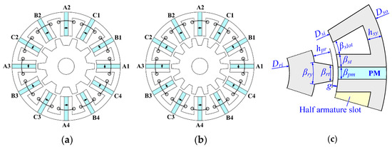
Figure 1.
Configuration of the FSPM machines. (a) 12/10. (b) 12/14. (c) Design parameters.

Table 1.
Main design specifications.
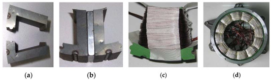
Figure 2.
Modular manufacturing process of the machine prototype. (a) Iron segments. (b) Segmented cell. (c) Single-cell wound. (d) Accomplished stator.
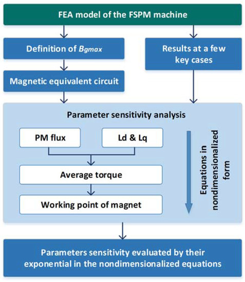
Figure 3.
Flowchart of the parameter sensitivity analysis process.
2. Local Maximum Air-Gap Flux Density (Bgmax) and Magnetic Equivalent Circuit
First of all, the magnetic equivalent circuit of the FSPM machine is introduced. Only the rotor position where phase-A flux (ΦmA) achieves peak value will be discussed, since it is directly related to the d-axis PM flux and thus the torque value. The MEC provides the bridge between the design parameters and electromagnetic performances. Figure 4 shows the flux distributions at d-axis when ΦmA achieves peak value, and Figure 5 shows the corresponding flux density distributions along the air gap. As can be seen, the local maximum flux density appears where one rotor pole fully overlapped with the stator tooth in coil-A1, defined as Bgmax. Although the Bgmax is lower than the peak flux density along the air gap, as shown in Figure 5, it is more presentative than the absolute maximum value, since it is directly related to the phase-A flux linkage, and further the PM flux linkage of the FSPM motor.
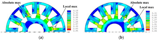
Figure 4.
PM flux distributions when rotor is at d-axis. (a) 12/10 machine. (b) 12/14 machine.
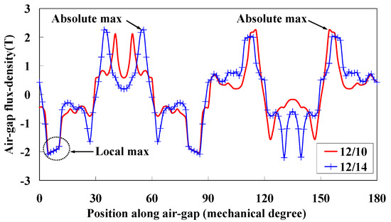
Figure 5.
PM flux density distributions along air gap when rotor is at d-axis.
Based on the field distributions shown in Figure 4, a simplified MEC model for the FSPM machine can be obtained as shown in Figure 6. As can be seen, the air gap flux density at the position where the stator tooth surrounded by coil-A1 is fully overlapped with one rotor pole directly results in the maximum PM flux of coil-A1; thus, this will be used to calculate the flux linkages in coil-A1.
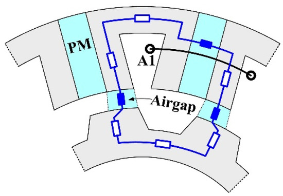
Figure 6.
The MEC model and parameter specifications when rotor is at d-axis.
3. Investigation on the Parameter Sensitivities
Based on the MEC mode, the sensitivities of electromagnetic performances on parameters in the FSPM machine is studied in this part. Specifically, the influences of design parameters on the dominant electromagnetic characteristics, i.e., the PM flux, d-axis and q-axis inductances, average torque, power factor angle, and the working point of magnets are investigated. More attention is paid to the split ratio, i.e., the ksio which is defined as ksio = Dso/Dsi, since it is directly related to the performances and more presentative.
3.1. PM Flux Linked by Armature Windings
When the Bgmax is defined, the PM flux in one stator pole Φp can be obtained by
Φp is not fully linked by coil-A1, Figure 7 shows the PM flux leakages Φleak by different split ratios. Thus, the flux linked by coil-A1, Φcoil, can be given by
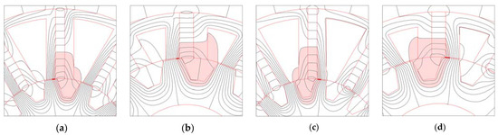
Figure 7.
Field distributions d-axis where the shadowed area refers to the leakage flux. (a) 12/10, ksio = 0.5. (b) 12/10, ksio = 0.7. (c) 12/14, ksio = 0.5. (d) 12/14, ksio = 0.7.
The flux leakage coefficient kflux is introduced into Equation (1) to taking into account the leakage fluxes, then Φcoil can be given by
The PM flux of one phase Φm is given by
where Pc is the coil count per phase. Now the relationship between Φm and the key design parameters is built. To reveal the parameter sensitivities, the nondimensionalized form is introduced, which removes complex and tedious equations, but leaves the key characters in equations that present the correlation degree between the optimal goal and the parameters. The nondimensionalized form of Equation (4) can be given by
Figure 7 also reveals that both the main PM flux and flux leakages increase with ksio, and the square root relation between Φm and ksio can be expected. The FEA results also indicates that, with satisfied accuracy, k*flux can be given by
Thus, Equation (5) can be further expressed by
Equation (7) is validated by Figure 8 which compares the d-axis flux with good agreements where the base results for nondimensionalization is obtained at ksio = 0.5. Equation (7) also reveals that the PM flux-linking armature windings is more sensitive to the split ratio than the other design dimensions.
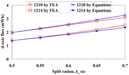
Figure 8.
Comparison of the d-axis fluxes given by FEA and Equation (7).
3.2. d-Axis and q-Axis Inductances
The above analysis discussed the relationship of no-load performances with parameters. The study of loaded performances is started with investigation into the d-axis and q-axis inductances. First of all, Figure 9 and Figure 10 present the field distributions in 12/10 and 12/14 machines when phase-A current is applied, where the blue lines indicate flux paths. The rotor positions at both the d-axis and q-axis are included. The blue solid lines indicate the path of the main fluxes, and the red dashed lines indicate the path of the leakage fluxes. As can be seen, when the rotor is at the d-axis, the permanent magnets wounded by coil-A1 and coil-A2 contribute the dominant magnetic reluctance of the main flux paths, which is decided by kpm, ksio and kst. Additionally, when the rotor is at the q-axis, the air gap near the stator teeth of coil-A1 and coil-A2 provide the dominant magnetic reluctance of the main flux paths, which is also decided by kpm, ksio and kst. With good accuracy, the nondimensionalized Ld, Lq can be given by Equation (8).
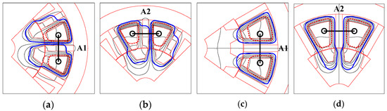
Figure 9.
Field distributions in the 12/10 FSPM machine when only phase-A current is applied (a) coil-A1, at d-axis; (b) coil-A2, at d-axis; (c) coil-A1, at q-axis; (d) coil-A2, at q-axis.
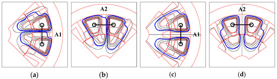
Figure 10.
Field distributions in the 12/14 FSPM machine when only phase-A current is applied: (a) coil-A1, at d-axis; (b) coil-A2, at d-axis; (c) coil-A1, at q-axis; (d) coil-A2, at q-axis.
Taking into account the stack length (la) and turns per coil (Na), Equation (8) can be further presented by
Figure 11 compares the Ld and Lq calculated by FEA and Equation (9) in the 12/10 and 12/14 FSPM machines, where the base results for nondimensionalization is obtained at ksio = 0.5. As can be seen, good agreement is achieved.
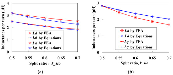
Figure 11.
The d-axis and q-axis inductances by FEA and Equation (9): (a) 12/10 machine; (b) 12/14 machine.
3.3. Electromagnetic Torque
The average torque will be discussed here. Usually, id = 0 control is adopted by the FSPM machines, and the electromagnetic torque Te is calculated by
Considering,
where, Ncoil and As are armature windings turns per coil and electrical load along air-gap (AT/m), As is given by
Bring Equations (11) and (12) into Equation (10), Te can be given by
With acceptable accuracy, it can be considered Ps/Pr ≈ 1 since it is normally Ps = Pr ± 2 in the FSPM machines, so Equation (13) can be simplified as
Then the nondimensionalized form Te* can be given by
Bringing Equation (7) into Equation (14), Te* can be presented by
Equation (16) indicates that for a FSPM machine, the relationship between Te and ksio and As can be given by (keeping other parameters such as B*gmax, k*stw unchanged)
On the other hand, to keep the Te unchanged with the variation of design parameter, As and ksio should fit in Equation (18)
Figure 12 gives the torque waveform when As and ksio fit in Equation (18). As can be seen, nearly the same average torque is achieved in the 12/10 and 12/14 machines, respectively, which also validates Equation (18).
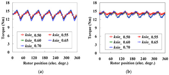
Figure 12.
The torque waveforms when As and ksio fit in Equation (18): (a) 12/10 machine; (b) 12/14 machine.
3.4. Power Factor Angle
The id = 0 control strategy is adopted in the FSPM machine due to a close Ld and Lq values, which inevitably reduces the power factor and increases the power factor angle. Thus in this part, the influences of design parameters on power factor angle is discussed. The vector frame is shown in Figure 13, and the tangent value of power factor angle φ can be given by
where Λq is the q-axis magnetic permeance. Then the nondimensionalized form, (tanφ)*, can be given by
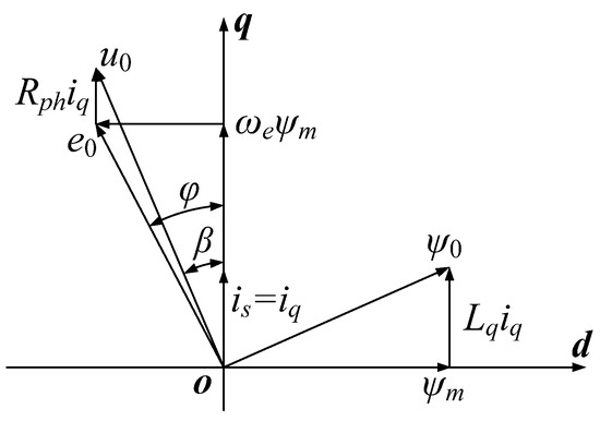
Figure 13.
Vector frame employing id = 0 control strategy.
Equation (20) shows that using larger kpm and ksio will reduce tan φ, thus increasing the power factor, since larger kpm and ksio indicates a stronger PM field and a weaker armature reaction. Moreover, according to Equation (18), when the same torque is achieved the relationship between tan φ and ksio can be given by bringing Equation (18) into Equation (20)
Figure 14 gives the variation of tan φ when the parameters fit in Equation (18) and, as can be seen, good agreements are achieved between FEA and Equation (21).
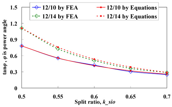
Figure 14.
Comparison of the tan φ values given by FEA and Equation (21).
3.5. Working Point of the PMs
It is usually appreciated by a PM machine that the PMs works at the maximum energy product point. Thus, the working point of the PMs in the FSPM machine is discussed in this part. First of all, the working point of a PM (Bpm) is defined as
where Belem-i and Selem-i is the flux density and area of the ith element of the PM meshes in the FEA model. As can be seen from Figure 15, Bpm varies with the rotor position and ksio since the magnetic circuit branches vary greatly.
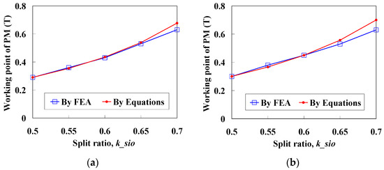
Figure 15.
Comparison of the working point of PM (Bpm) due to different ksio. (a) 12/10 machine. (b) 12/14 machine.
It should be noticed that the leakage flux is include in Φpm. Then, considering
It can be obtained that
Then, the nondimensionalized form B*pm can be given by
Figure 15 gives the PM working point (Bpm) values due to different ksio, where Bpm is the average value in one electrical cycle. As can be seen, good agreements are achieved between FEA results and Equation (21) predictions.
It should be emphasized that the proposed MEC method only covers the average performance in one electrical circle, e.g., the d-axis flux by magnets, average torque, etc., while the time-step-related performances such as torque ripples are not included, since only the rotor positions at d-axis and q-axis are considered.
4. Considerations Regarding Manufacturing Tolerances and Robust Approach
As mentioned in Section 1, the FSPM machine is a modular manufacturing method and the stator is combined by 12 segments. Although the modular stator facilitates the fabricating process and better copper fill, it will also generate large tolerances than traditional manufacturing methods, e.g., the uneven air gap length and concentricity errors, and leads to unbalanced radial forces and vibration. Thus, the influences of air-gap length on average and radial forces are studied in this section. Moreover, the robust design approach for the FSPM machine is briefly introduced, which aims to achieve best machine stability and robustness by setting boundaries on design dimensions, when taking into account the manufacturing tolerances.
4.1. Air-Gap Length and Key Performances
Inaccurate concentricity of the stator iron can hardly be avoided when assembling the modular segments into a housing/shell, which will lead to inaccurate air-gap lengths. Hence, a slightly smaller air-gap length might greatly increase the requirement of manufacturing accuracy and thus lead to higher costs during mass production. Therefore, special attention is paid to air-gap length firstly in this part. As can be seen from Figure 16 and Table 2, the torque output is reduced by only 9% when the air gap is increased by nearly 35~50%; meanwhile, the variations of loaded-phase EMF and cogging torque values can be neglected. This reveals that a larger air-gap length is preferred in the FSPM machine, since it can balance the slight drop of torque output and significantly reduce manufacturing difficulties and costs. In addition, a larger air gap will also reduce the unbalanced radial forces on rotor, as will be presented in next part.
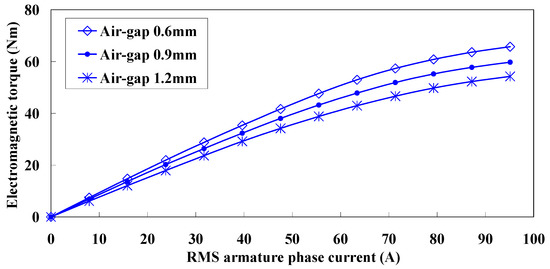
Figure 16.
Comparison of the torque output by different air-gap lengths.
Table 2.
Performances under different air-gap lengths by 2D FEA.
4.2. Unbalanced Radial Forces on Rotor
The inaccurate stator concentricity might be generated by assembly tolerances, especially when modular segments are adopted. This will cause uneven air-gap lengths and unbalanced radial forces on the rotor, also called unbalanced magnetic pull (UMP). Although a precisely balanced rotor is preferred in these machines, it is hard to be obtained in integrated starter generator (ISG) systems in HEVs, where the rotor is directly coupled to the flywheel of the engine; consequently, the vibration of the engine may affect the concentricity of the electric motors. The unbalanced forces will lead to increased power loss, greater acoustic noise, vibration and thus degraded electrical isolations. Therefore, it is worth paying attention to this force. Based on 2D FEA, to simplify the analysis, the unbalanced forces are investigated by adopting an eccentric rotor with a bias of 0.3 mm from the stator center and towards coil-A1, as shown in Figure 17. Different air-gap lengths (under healthy conditions) are also considered.
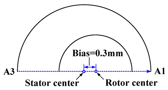
Figure 17.
Illustration of the eccentric rotor with a bias from stator center and towards coil-A1.
Figure 18 and Figure 19 give the unbalanced forces in one electrical period. Interestingly, the no-load unbalanced forces, i.e., due to PMs only, exhibit similar amplitudes (near 600 N) under different air-gap lengths, as can be seen in Figure 18, while the unbalanced forces under loaded conditions drop greatly when the air gap increases (from 820 N when g = 0.6 mm to 480 N when g = 1.2 mm), as shown in Figure 19. Meantime, the variations of other electromagnetic performances when the rotor bias occurs, e.g., winding inductances, back-EMF and electromagnetic torque waveforms, et al., can be neglected.
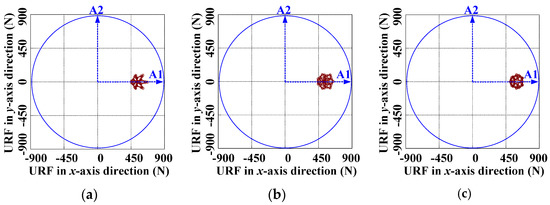
Figure 18.
Unbalanced radial forces on rotor under no-load condition, when rotor bias is 0.3 mm. (a) Air-gap = 0.6 mm. (b) Air-gap = 0.9 mm. (c) Air-gap = 1.2 mm.
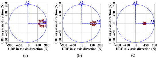
Figure 19.
Unbalanced radial forces on rotor under loaded condition, when rotor bias is 0.3 mm. (a) Air-gap = 0.6 mm. (b) Air-gap = 0.9 mm. (c) Air-gap = 1.2 mm.
Overall, a relatively large air-gap length will contribute to the stability and robustness of the FSPM machine, thus a longer possible machine life, only with the acceptable drawback of slightly reduced torque output.
4.3. Robust Design Approach
Provided that manufacturing tolerances of dimensions follow the normal distribution, it can be derived that the electromagnetic and mechanical performances, e.g., the noise level, also follow the normal distribution. As can be seen from Figure 20a, the possibility of failed level, i.e., in the failure region can be significantly reduced in the optimized machine, by a robust design approach. However, this method may degrade the electromagnetic performances, since it aims at enhanced robustness, as shown in Figure 20b, where the regions R1 and R2 indicate the degraded electromagnetic capabilities and improved ones, respectively. Overall, maximizing region R2 while minimizing R1 is desired by the robust design approach. More details will be presented in a coming paper.
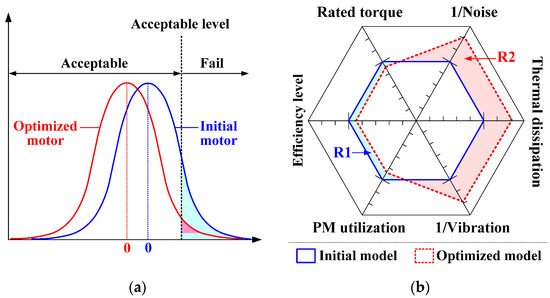
Figure 20.
Illustration of the robust design approach for FSPM machine. (a) Normal distribution. (b) Graph of dimensions.
5. Experimental Validations and the Robust Design Approach
In this part, the experimental validations are carried out. Due to the relatively low ratios of stack length to stator outer diameter of the FSPM machine, the end-effect will cause considerable flux leakage along the axial direction, and hence, the 3D FEA predicted steady-state performances are compared to the experimental measurements as shown in Figure 21. As can be seen, good agreements are achieved, and due to saturation, the torque–current curve exhibits seriously nonlinear variation when the phase current exceeds 55A (RMS).
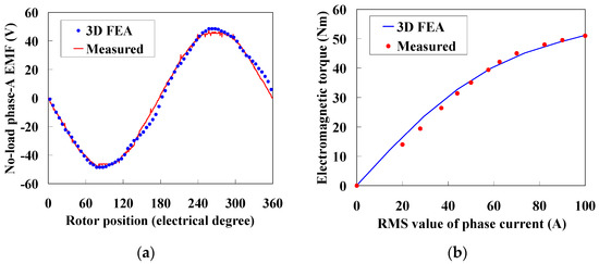
Figure 21.
Comparison of the 3D FEA predicted and experimental measured performances. (a) No-load phase-A EMF waveforms at 1000 r/min. (b) Average electromagnetic torques.
6. Conclusions
Based on the magnetic equivalent magnetic circuit model, the parameter sensitivity analysis of the FSPM machine is carried out in this paper. Unlike the traditional methods, the proposed MEC-based method only needs FEA calculation of a few key cases, and thus is less time consuming, while obtaining satisfactory accuracy. The parameters’ sensitivities are evaluated by their exponential in the nondimensionalized equations, and can be adopted to accelerate the multiobjective optimization of flux-switching machines in future work. It should be emphasized that the proposed MEC method only covers the average performance in one electrical circle, e.g., the average torque, PM flux, etc., while the time-step-related performances such as torque ripple are not included. Thereafter, focused on the influences of air-gap length on torque and unbalanced radial forces, the modular manufacturing method is discussed. Overall, a relatively large air-gap length will contribute to the stability and robustness of the FSPM machine. Finally, the robust design approach for the FSPM machine is introduced, which aims at best machine stability and robustness when taking into account the manufacturing tolerances. Experimental validations are also presented.
Author Contributions
Conceptualization, G.Z.; data curation, Q.T.; formal analysis, G.Z. and A.Q.; funding acquisition, Z.C.; investigation, G.Z., Q.T. and A.Q.; methodology, G.Z., Z.C. and X.X.; supervision, G.Z. and W.H.; writing—original draft, G.Z. All authors have read and agreed to the published version of the manuscript.
Funding
This work is supported in part by the National Nature Science Foundation of China under Grant 61973073, 52077032, in part by CALT under Grant CALT201806, in part by the Fundamental Research Funds for The Central Universities under Grant 2242021R41129, and in part by the Technology Foundation for Selected Overseas Chinese Scholar under Grant 1116000256.
Institutional Review Board Statement
Not applicable.
Informed Consent Statement
Not applicable.
Data Availability Statement
Not applicable.
Conflicts of Interest
The authors declare no conflict of interest.
References
- Kurtović, H.; Hahn, I. Calculation of active material’s torque contributions for a flux switching machine. IEEE Trans. Magn. 2020, 56, 7508504. [Google Scholar] [CrossRef]
- Chen, Z.X.; Cui, Y.J. Numerical simulation and experimental validation of a flux switching permanent magnet memory machine. IEEE Access 2020, 8, 194904–194911. [Google Scholar] [CrossRef]
- Hua, W.; Cheng, M.; Zhu, Z.Q. Analysis and optimization of back-EMF waveform of a flux-switching permanent magnet motor. IEEE Trans. Energy Convers. 2008, 23, 727–733. [Google Scholar] [CrossRef]
- Cheng, M.; Hua, W.; Zhang, J.Z. Overview of stator-permanent magnet brushless machines. IEEE Trans. Ind. Electron. 2011, 58, 5087–5101. [Google Scholar] [CrossRef]
- Chan, C.C. The state of the art of electric, hybrid, and fuel cell vehicles. Proc. IEEE 2007, 95, 704–718. [Google Scholar] [CrossRef]
- Zhang, G.; Hua, W.; Cheng, M. Design and comparison of two six-phase hybrid-excited flux-switching machines for EV/HEV applications. IEEE Trans. Ind. Electron. 2016, 63, 481–493. [Google Scholar] [CrossRef]
- Wang, P.X.; Hua, W.; Zhang, G.; Wang, B.; Cheng, M. Torque ripple suppression of flux-switching permanent magnet machine based on general air-gap field modulation theory. IEEE Trans. Ind. Electron. 2021. Early access. [Google Scholar] [CrossRef]
- Zeng, Z.Q.; Shen, Y.M.; Lu, Q.F.; Gerada, D.; Wu, B.; Huang, X.Y.; Gerada, C. Flux-density harmonics analysis of switched-flux permanent magnet machines. IEEE Trans. Magn. 2019, 55, 8103607. [Google Scholar] [CrossRef]
- Wang, D.H.; Wang, X.H.; Jung, S.Y. Reduction on cogging torque in flux-switching permanent magnet machine by teeth notching schemes. IEEE Trans. Magn. 2012, 48, 4228–4231. [Google Scholar] [CrossRef]
- Wang, P.X.; Hua, W.; Zhang, G.; Wang, B.; Cheng, M. Principle of flux-switching permanent magnet machine by magnetic field modulation theory part I: Back-electromotive-force generation. IEEE Trans. Ind. Electron. 2022, 69, 2370–2379. [Google Scholar] [CrossRef]
- Wang, P.X.; Hua, W.; Zhang, G.; Wang, B.; Cheng, M. Principle of flux-switching pm machine by magnetic field modulation theory part II: Electromagnetic torque generation. IEEE Trans. Ind. Electron. 2022, 69, 2437–2446. [Google Scholar] [CrossRef]
- Wang, P.X.; Hua, W.; Zhang, G.; Wang, B.; Cheng, M. Inductance characteristics of flux-switching permanent magnet machine based on general air-gap filed modulation theory. IEEE Trans. Ind. Electron. 2021. Early access. [Google Scholar] [CrossRef]
- Zhu, Z.Q.; Pang, Y.; Howe, D. Analysis of electromagnetic performance of flux-switching permanent-magnet machines by nonlinear adaptive lumped parameter magnetic circuit model. IEEE Trans. Magn. 2005, 41, 4277–4287. [Google Scholar] [CrossRef]
- Ilhan, E.; Gysen, B.L.J.; Paulides, J.J.H. Analytical hybrid model for flux switching permanent magnet machines. IEEE Trans. Magn. 2010, 46, 1762–1765. [Google Scholar] [CrossRef] [Green Version]
- Gysen, B.L.J.; Ilhan, E.; Meessen, K.J. Modeling of flux switching permanent magnet machines with Fourier analysis. IEEE Trans. Magn. 2010, 46, 1499–1502. [Google Scholar] [CrossRef] [Green Version]
- Zhu, S.; Cheng, M.; Hua, W.; Cai, X.H.; Tong, M.H. Finite element analysis of flux-switching pm machine considering oversaturation and irreversible demagnetization. IEEE Trans. Magn. 2015, 51, 7403404. [Google Scholar] [CrossRef]
- Sulaiman, E.; Kosaka, T. Parameter sensitivity study for optimization of field-excitation flux switching synchronous machine for hybrid electric vehicles. In Proceedings of the 2012 7th IEEE Conference on Industrial Electronics and Applications (ICIEA), Singapore, 18–20 July 2012. [Google Scholar] [CrossRef]
- Xiang, Z.X.; Zhu, X.Y.; Quan, L.; Fan, D.Y. Optimization design and analysis of a hybrid permanent magnet flux-switching motor with compound rotor configuration. CES Transact. Electr. Mach. Syst. 2018, 2, 200–206. [Google Scholar] [CrossRef]
- Chen, Y.Y.; Zhuang, J.H.; Ding, Y.; Li, X.J. Optimal design and performance analysis of double stator multi-excitation flux-switching machine. IEEE Trans. Appl. Supercond. 2019, 2, 0601205. [Google Scholar] [CrossRef]
- Yu, J.C.; Liu, C.H. Multi-objective optimization of a double-stator hybrid-excited flux-switching permanent-magnet machine. IEEE Trans. Energy Convers. 2020, 35, 312–323. [Google Scholar] [CrossRef]
- Ullah, W.; Khan, F.; Umair, M. Multi-objective optimization of high torque density segmented PM consequent pole flux switching machine with flux bridge. CES Transact. Electr.Mach. Syst. 2021, 5, 30–40. [Google Scholar] [CrossRef]
- Sun, H.; Yang, J. Optimal decisions for competitive manufacturers under carbon tax and cap-and-trade policies. Comput. Ind. Eng. 2021, 156, 107244. [Google Scholar] [CrossRef]
- Foumani, M.; Jenab, K. Cycle time analysis in reentrant robotic cells with swap ability. Int. J. Product. Res. 2012, 50, 6372–6387. [Google Scholar] [CrossRef]
- Sulaiman, E.; Zakaria, S.N.U.; Kosaka, T. Parameter sensitivity study for optimization of single phase E-Core hybrid excitation flux switching machine. In Proceedings of the 2015 IEEE International Conference on Mechatronics (ICM), Nagoya, Japan, 6–8 March 2015. [Google Scholar] [CrossRef]
- Zhao, W.J.; Qiu, X.; Bu, F.F.; Yang, J.F.; Fan, W.X. Study on influence of structure parameters on electromagnetic characteristics for 12/10 flux-switching permanent magnet motor. In Proceedings of the 2019 IEEE 13th International Conference on Power Electronics and Drive Systems (PEDS), Toulouse, France, 9–12 July 2019. [Google Scholar] [CrossRef]
- Lei, G.; Wang, T.S.; Zhu, J.G. System-level design optimization method for electrical drive systems−robust approach. IEEE Trans. Ind. Electron. 2015, 62, 4702–4713. [Google Scholar] [CrossRef]
Publisher’s Note: MDPI stays neutral with regard to jurisdictional claims in published maps and institutional affiliations. |
© 2022 by the authors. Licensee MDPI, Basel, Switzerland. This article is an open access article distributed under the terms and conditions of the Creative Commons Attribution (CC BY) license (https://creativecommons.org/licenses/by/4.0/).