Abstract
The development of electromobility involves the development of electric cars charging infrastructure. The increase of the number of chargers poses new demands for the AC power grid, especially in regard to its capacity of delivering high peak power. As an alternative for the public AC power grid, urban electrified transportation systems (trams, trolleybuses, and metro) can be used for supplying electric cars chargers. The article discusses four options of integrating electric cars chargers with a traction power supply system. The option of connecting the charger to the traction overhead supply line has been selected due to the spatial availability of the power source and possibility to use regenerative braking energy for charging. A set of criteria has been developed for analysing the capability of the traction supply system to feed electric cars chargers. An exemplary feasibility analysis was carried out for trolleybus traction supply system in Gdynia, Poland. The impact of installing the charging station on specific traction supply parameters has been predicted using present-state recordings of electrical parameters and assumed charging station power. The study shows that every supply section of the considered trolleybus traction system has the capability of installing a fast-charging station, which provides opportunities of expanding the charging stations network in Gdynia.
1. Introduction
The expansion of electromobility requires the development of the electric power distribution infrastructure. In particular, it is essential to provide a dense network of electric cars charging stations. This, in turn, leads to the increased demand for power and energy drawn from the power distribution system, which often requires substantial development of this system [1]. The use of modern smart grid technologies, such as Vehicle to Grid (V2G) [2,3], can be extremely useful for this purpose. Thanks to V2G technologies, electric vehicles can act as power-balancing prosumers, supporting the power system [4,5].
V2G technologies are usually associated with the commercial AC power grid [6,7]. However, an electric vehicle may also be a prosumer in the electric traction power supply system of railways, trams, or trolleybuses. As the power demand in traction supply systems varies in a much wider range than in commercial systems [8], the demand for power-balancing means is even more significant [9,10]. The authors of [11] proposed to use electric vehicles charging stations installed at the Kochi Metro Rail System to support the supplying grid in terms of load balancing, harmonic elimination, and reactive power compensation. By simulation and experimental study, it has been proven that charging stations connected to the step-down transformer of a metro traction substation can act as an ancillary service provider.
The peak load limitation of the AC distribution network raises reasonable concerns in regard to grid stability under the load of electric car chargers [12]. The most commonly proposed solution to this problem is integrating the chargers with energy storages and photovoltaic systems [13]. The first flattens the power demand of the charger, while the latter partially covers this demand. However, due to the required ratings of these devices, their cost is substantial. Therefore, an interesting solution to overcome the peak load limitation of the AC distribution grid is to supply part of the charging stations from urban traction power supply systems. Such systems usually have a large peak power reserve, which may be used to cover the power demand of additional devices [14]. As parking lots with electric car chargers are often located near transportation nodes, the integration of chargers with traction power supply systems does not require long power cables [5,12].
A charger supplied by the urban traction power supply systems may be connected to a power substation (as assumed in [11]) or to the DC traction overhead line. The second solution provides additional benefits, such as the large spatial availability of the overhead line. Moreover, a substantial part of traction power systems is equipped with energy storage systems, which collect energy from the regenerative braking of the vehicles. Such storage is usually connected to the DC part of the system and—when merged with electric vehicles charges—may potentially create a flexible smart grid system [8].
An interesting study of integrating electric vehicle chargers has been reported in [13]. The authors considered supplying electric vehicle chargers from the 750 V DC traction overhead line of a public tram in Edinburgh, Scotland. The study discusses charging control strategies, as well as earthling and wider system protection requirements. Another study [15] analyses charging stations supplied from the trolleybus DC traction overhead line in Solingen, Germany. The authors propose a multi-vehicle-charging concept, which maximizes the charge points availability despite power limitations present on the supply level.
This article includes an exemplary assessment of the feasibility of using a trolleybus power system for supplying electric car charging stations. Four options of integrating electric car chargers with a traction power supply system have been discussed. The option of connecting the charger to the traction overhead supply line has been selected, as it provides particular advantages when compared to the supply from the public AC grid. The present state of trolleybus traction power supply in Gdynia has been evaluated by the analysis of recordings carried out in traction substations and vehicles. Next, using the linear nature of the system, the power supply parameters were corrected according to the assumed power of the charging stations. Finally, the parameters were evaluated in regard to the proper operation of the system. The evaluation shows that the trolleybus traction power supply in Gdynia has substantial reserves and could be used to supply fast charging stations.
2. Options of Integrating Chargers into the Trolleybus Power Supply System
Trolleybuses are powered by an overhead dual-pole DC traction contact line. The traction line is divided into supply sections (Figure 1). Individual sections are powered by supplying wires (so-called feeders) from traction substations. The traction substations transform the AC power into DC and decreases the voltage to a suitable level. The nominal DC voltage in a trolleybus supply system, ranges from 600 to 725 V. Due to voltage drops at the feeders and at the overhead line, the idle output voltage of substations is set approximately to 110% of the rated value, i.e., 660 V or 825 V [16].
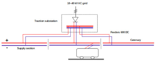
Figure 1.
General scheme of trolleybus power supply system.
The connection of vehicle charging stations and the urban transport energy system can be carried out in different manners, which is shown in Figure 2.
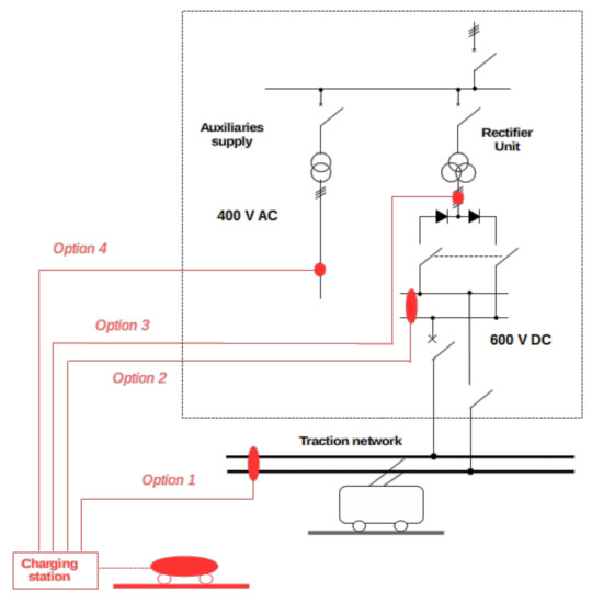
Figure 2.
Possibilities of supplying electric vehicle charging stations from a traction power system.
The charging station may be connected to the DC level, i.e., directly to the traction overhead line (option 1 in Figure 3) or to the DC busbars in the substation (option 2). Such solutions allow the best synergy between the systems, mainly due to the possibility of directing the trolleybuses regenerative braking energy to the charging stations. An additional advantage of drawing the power from the overhead contact line (option 1) is the large spatial accessibility of the overhead traction line. The power that can be drawn from the overhead line by the charging station depends on the distance from the traction substation and the design of the traction network. Under favourable conditions (close proximity to the substation and large cross-section of the overhead line), it can be at the level of 200–300 kW, but in most cases the available power is approximately 50–100 kW. Supplying the charging station from the DC part of the traction power system (both options 1 and 2) requires the use of a DC/DC power-electronic converter, which is not a typical solution, thus substantially increasing the costs of the system. In turn, powering the charging stations from the AC voltage (options 3 and 4) uses standard solutions, which makes it inexpensive. However, the AC voltage is available only in traction substations. A detailed comparison of all the options is included in Table 1.
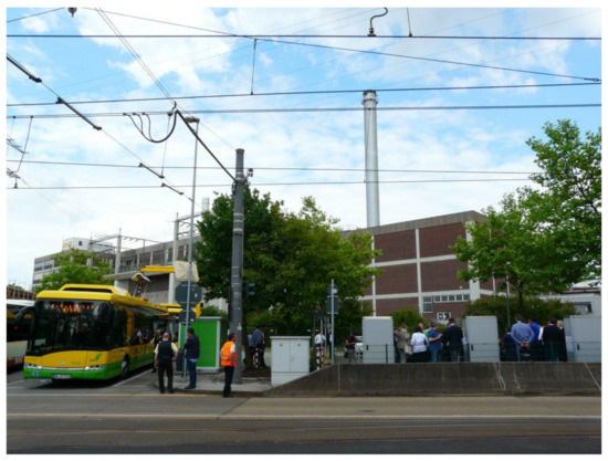
Figure 3.
Charging station for electric bus and electric cars powered from the tram overhead line in Oberhausen, Germany.

Table 1.
Comparison of the possibilities of supplying electric vehicle charging stations from traction power system.
The exemplary electric vehicles charging system powered by the tram overhead line has been launched in Oberhausen, Germany (Figure 3). It consists of a DC/DC converter (Figure 4), three electric cars charging stations and one electric bus charging station.
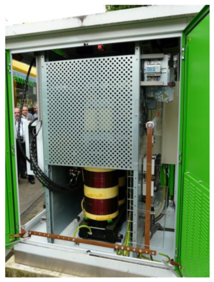
Figure 4.
DC/DC converter used for powering a charging point for electric buses and cars from a tram overhead line in Oberhausen, Germany.
3. Electric Cars Charging Station in Gdynia, Poland
In the city of Gdynia (Poland), a converter station that allows the use of a traction system to supply receivers with industrial voltage of 400 V AC was launched in 2021 as a result of the “EfficienCE” project [17]. The converter links a trolleybus overhead line to an electric vehicle charging hub.
In order to increase the reliability of the power supply (e.g., in the event of excessive drops of converter input voltage) and to increase the flexibility of accumulation of trolleybuses regenerative braking energy, the station was equipped with a battery-based electric energy storage. For this purpose, a second-life traction battery from a trolleybus was used (Figure 5).
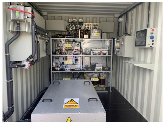
Figure 5.
DC/AC converter for conversion converting trolleybus 600 V DC overhead line voltage into a 400 V AC commercial standard (operating in Gdynia, Poland; the battery-based energy storage is in the box placed on the floor).
The power conversion process is split into two stages (Figure 6). First, the system uses the DC/DC converter, which provides galvanic separation from the traction network voltage and regulates the battery charging current [18]. Next, the DC/AC converter delivers the power to the charging station via an additional transformer used for insulation purposes. The charging station is supplied by 3 × 400 V AC, which is a commercial standard. Hence, a typical fast charger for electric cars was used.
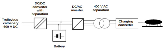
Figure 6.
General connection scheme of the charging station and the trolleybus power supply line in Gdynia, Poland.
4. Feasibility of Using Trolleybus Traction System for Supplying Chargers
The solution of using a trolleybus traction system to supply electric vehicle chargers, presented in the previous section, which has been a subject of a trial operation, proves the technological maturity of the required equipment. However, the selection of target locations of similar solutions requires comprehensive analysis.
Traction power supply systems are featured by high load variability, which is a result of a variable number of vehicles within the supply section and their variable driving state [19]. The power demand may suddenly change from large positive (few vehicles simultaneously accelerating) to idle or even negative (regenerative braking) in a few seconds. The variable load causes large voltage fluctuations in the overhead contact line. For this reason, it requires specialized tools for energy analyses.
The analysis presented in this section uses data recorded from the trolleybus traction supply network in Gdynia. In addition, data from trolleybuses on-board recorders were used.
In order to determine the possibilities of using the trolleybus network to supply charging stations, an analysis of the load level and voltage in overhead supply lines of the trolleybus system was carried out. Supplying the charging station from the trolleybus overhead line is associated with an increase in the overhead line load. The following limitations for this increase should be considered at particular supply sections:
- Maximal current load,
- Maximal allowable voltage drop,
- Maximal acceptable transmission losses.
The above limitations are summarized in Table 2 and discussed in the following subsections.
Table 2.
Criteria for verification of possibility to use trolleybus overhead line to supply electric cars charging stations.
4.1. Criterion I: Maximal Load Current
The analysis was made with the assumption that the charging stations draw a constant power of 44 kW (2 stations, 22 kW each). Such a power was recalculated into the load current (approximately, 80 A at the rated voltage 600 V and 100 A upon a voltage drop to 400 V) and added to the current recorded during trolleybus power system operation.
The results of the analysis of the current load on particular power sections in the trolleybus supply system of Gdynia are presented in Figure 7. The analysis is based on recordings carried out during low ambient temperature period, which translates to the highest power demand related to electric heating of the trolleybuses [20]. The maximum value of the load is approximately 300 A, which provides a large margin when compared to the limit of 840 A. Hence, it is concluded that the additional load would not result in exceeding the maximal load current value.
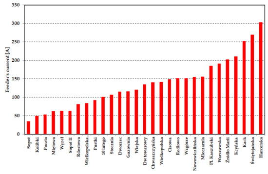
Figure 7.
Results of computation of average load current of particular supply sections (assumed power of the charging station: 44 kW).
4.2. Criterion II: Maximal Voltage Drop
In association to criterion 2C, described in Table 2, Figure 8 presents the results of recordings of the average useful voltage on trolleybus collectors grouped into individual power sections. The input data were obtained from on-board trolleybuses recorders.
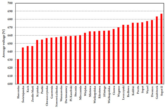
Figure 8.
Average voltages at trolleybuses current collectors on particular supply sections (no charging station).
With the exception of the “Harcerska” section, which is presently undergoing modernization, the voltage values are in the range between 645 V and 685 V. The output voltages of the substations are set at the level of 680–690 V. Hence, the average drop does not exceed 50 V, which provides a large margin to the permitted value of 99 V.
The additional load related to the charging station for electric cars would increase the voltage drops presented in Figure 8. Due to the linear nature of the electric circuits, the total voltage drop may be calculated by means of superposition, i.e., as a sum of present voltage drop and the drop related to the charging stations. Instantaneous drop Δdrop related to the charging stations may be calculated as:
where: Ichar is the current collected by the charging stations and Rk is the short circuit resistance of the overhead line at the point of the charging stations’ location.
The voltage drop, Δdrop, was computed for the most unfavourable conditions. The location of charging stations was assumed at the end of power section, which leads to the greatest value of resistance Rk. Moreover, the power drawn by the charging stations was assumed constant and equal to 44 kW, which translates into Ichar = 83 A. Assuming constant Ichar makes the instantaneous voltage drop (1) equal to the average drop.
Table 3 lists the short circuit resistances and the increase in voltage drops for particular power sections. The computed values of the voltage drop range approximately from 7 to 37 V, which is far below the 50-V margin derived from the recordings (Figure 8).
Table 3.
Short circuit resistances and computed increase in voltage drops for particular power sections.
In association to criterion 2A, described in Table 2, Figure 9 shows the results of measurements of the minimum voltage level Umin in the Gdynia trolleybus network (green bars). It should be emphasized that due to the random nature of trolleybus operations, these values should be treated as indicative. In addition to the present state (green), Figure 9 includes the estimated minimum voltage Umin_char computed for assumed power of electric car charging stations: 22 kW (blue) and 40 kW (red). The computations were carried out for the most unfavourable case of positioning the charging stations at the end of the power supply sections. The values were obtained by decreasing the measured value of the minimal voltage drop by the additional voltage drop (1) caused by the charging stations.
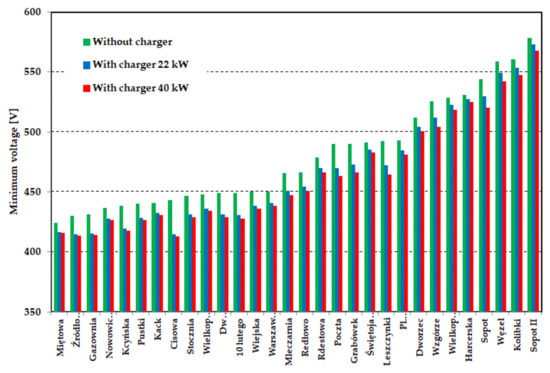
Figure 9.
Minimal instantaneous values of the supply voltage in the overhead contact line at particular supply sections.
Connecting a charging station would not cause the supply voltage to drop below 400 V. It should be noted that in the event of a supply voltage drop below 450 V, an unstable operation of the charging station may occur (switching off). However, such a situation occurs rarely, up to several times a week. To increase operational reliability, it is possible to equip the charging station with an energy storage. Unfortunately, this would increase the complexity of the system and increase investment costs.
Importantly, the voltage close to the given minimal values appear rarely (typically once a day, depending on the physical situation), which is confirmed by the analysis of the relative time of the drops (Figure 10). Most of the time, the voltage in the overhead contact line is above 600 V.
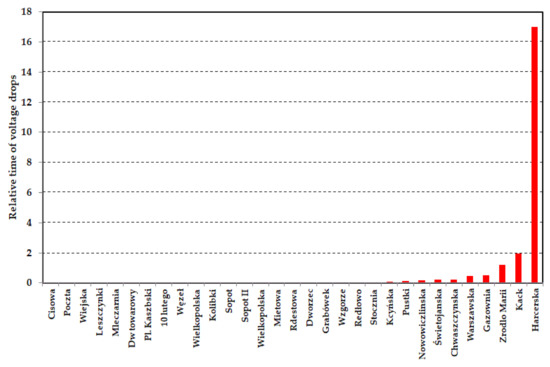
Figure 10.
Relative time of voltage decrease below 500 V for particular power supply sections, expressed in per mills.
4.3. Criterion III: Acceptable Power Transmission Losses
During power delivery to the trolleybuses, energy transmission losses Eloss in the power supply system appear in the feeders and the traction overhead line [21]. The increase of delivered power, resulting from installing the charger, would additionally increase these losses, which should be taken into account when settling with the charging system operator. The calculations of losses presented in this section were made using a method presented in [22], based on data from on-board trolleybus recorders.
The trolleybus current of value Iveh increases the substation load current by the same amount Iveh, however the voltage at the current collector Uveh differs from the substation output voltage Us due to the losses. This difference may be used to evaluate the losses in the following manner.
The power consumption of a trolleybus is be defined as:
The power drawn by the trolleybus from the substation is:
The losses related to transmission of the power to the trolleybus may be therefore computed as:
Figure 11 shows the values of transmission energy losses graphically. For most of the power supply sections, transmission losses are at the level of 5–7%, which is significantly below the recommended value, thus the charging stations can be connected there. The greatest losses occur in the “Harcerska” power section, which—as indicated before—is subject to modernization, thus the losses will be decreased there. As an important non-technical issue, the losses related to energy transmission arising in the trolleybus overhead line should be taken into account in settlements with the operator of the charging point.
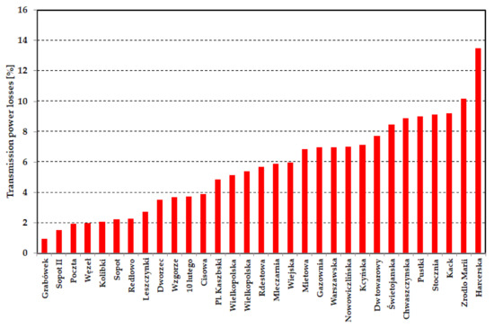
Figure 11.
Percentage transmission losses of supply sections.
4.4. Summary of All Criteria and Practical Problems
The power of the electric car charger is much lower than the power consumed by trolleybuses, thus it will only slightly increase the load on the power supply system. Therefore, the criteria for assessing the I and III power systems (Table 2) are not of key importance. On the other hand, the voltage criterion is important: criterion II. Due to the high resistance of the trolleybus supply system, excessive voltage drops occur. They can hinder the work of trolleybuses and chargers.
Except from “Harcerska” section, which is presently undergoing modernization that aims at improving the power supply quality, all supply sections have the technical capability to feed the assumed charging station. For the case of Gdynia, there is a great reserve in criterion I that regards yjr maximal load current of feeders and overhead wires. The predicted load computed for the 44-kW charger does not exceed 33% of the maximal long-term load current. An evaluation of the other two criteria provides a moderate reserve. The narrowest margin of 13 V in the voltage drop criterion was evaluated for the “Cisowa” section. However, nearly half of the supply sections in Gdynia are featured by a voltage drop margin greater than 50 V. Transmission losses differ greatly for particular supply sections, and in some cases the value of losses is close to the assumed limit of 10%. However, the power losses criterion has economical background, exceeding the assumed limit that it would not result in technical faults.
As mentioned in Section 4.2, the minimum allowable voltage in the trolleybus overhead traction line is 400 V. As the power load in urban transportation systems is variable and random, the charging stations that are connected to the overhead traction line should include control algorithms that provide protection from the undervoltage condition, similar to the ones implemented in the vehicles [23]. If the supply voltage drops below 500 V, the charging power should be limited, and this power limit should linearly change with the voltage to ensure system stability. Upon 500 V, full charging power should be available and upon voltage decrease, this power should be limited, reaching zero upon 400 V, as presented in Figure 12. The technical possibility of the dynamic limitation of charging power has been proven in [15]. The proposed undervoltage protection may cause temporary interruptions to the charging process. However, they will be rare if the power and location of the charging station will be selected with respect to the criteria discussed above.
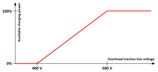
Figure 12.
Proposed charging power reduction strategy for protection from the undervoltage condition.
In order to ensure the safe and reliable operation of the whole system, the integration of the charging station into the traction power supply should also include remote supervision and control. Therefore, the charging station should be fitted with the same communication protocol as the traction equipment (e.g., SCADA).
5. Conclusions
Out of the four discussed solutions, this paper focused on supplying electric car chargers from the DC overhead traction line. This solution features good spatial availability of the power source and great potential for implementing V2G technologies. At the same time, the additional load introduced to the overhead line by the charger has an impact on specific supply parameters and raises concerns about the reliable operation of the transportation system. The capability of the DC overhead traction line to cover the additional load was verified for the exemplary case of trolleybus system in Gdynia.
The electrical parameters recordings show that the trolleybus overhead supply system in Gdynia is currently significantly below the limit values in terms of the current carrying capacity, voltage drops, and power losses. Computations applied for predicting the supply parameters after installing the charger proved that all supply sections (except from the one that is undergoing modernization) have the technical capability to feed the assumed charging station.
Due to the occasional emergency occurrences that appear in every traction system, the charging station should be equipped with the function of limiting the charging power when the voltage in the overhead contact line drops below 500 V. This limitation should be linear so as to not disturb the stability of the system. The application of energy storage would enable the charger to maintain high charging power upon supply voltage drops and increase the potential for implementing V2G technologies.
Using an example of trolleybus system in Gdynia, the paper shows the possibility of using the traction power supply system for charging electric cars. Gdynia, with nearly 250,000 inhabitants, has the trolleybus transportation system featured by the total length of the overhead line of approximately 100 km. Tram systems, which are much more popular worldwide, feature similar electrical and spatial parameters to the trolleybus systems. Hence, the interest in implementing electric car chargers into urban traction supply systems is expected to gain.
Author Contributions
Conceptualisation, M.B.; methodology, M.B.; software, M.B.; validation, L.J.; formal analysis, M.B.; investigation, R.H.; resources, L.J.; data curation, R.H.; writing—original draft preparation, M.B.; writing—review and editing, L.J.; visualisation, M.B.; supervision, L.J.; project administration, M.B.; funding acquisition, M.B. All authors have read and agreed to the published version of the manuscript.
Funding
This research was funded by Interreg CENTRAL EUROPE, within the framework of grant agreement no. CE1537, project title “EffcienCE—Energy Efficiency for Public Transport Infrastructure in Central Europe”.
Institutional Review Board Statement
Not applicable.
Informed Consent Statement
Not applicable.
Acknowledgments
The authors would like to thank Przedsiębiorstwo Komunikacji Trolejbusowej Sp. z o. o. w Gdyni (PKT) for sharing the results of the recordings that were used for the verification of the developed model.
Conflicts of Interest
The authors declare no conflict of interest.
References
- Grenier, A.; Page, S. The impact of electrified transport on local grid infrastructure: A comparison between electric cars and light rail. Energy Pol. 2012, 49, 355–364. [Google Scholar] [CrossRef] [Green Version]
- Freeman, G.; Drennen, T.; White, A. Can parked cars and carbon taxes create a profit? The economics of vehicle-to-grid energy storage for peak reduction. Energy Pol. 2017, 106, 183–190. [Google Scholar] [CrossRef]
- Krueger, H.; Cruden, A. Multi-layer event-based vehicle-to-grid (V2G) scheduling with short term predictive capability within a modular aggregator control structure. IEEE Trans. Veh. Technol. 2020, 69, 4727–4739. [Google Scholar] [CrossRef] [Green Version]
- Tomić, J.; Kempton, W. Using fleets of electric-drive vehicles for grid support. J. Power Sources 2007, 168, 459–468. [Google Scholar] [CrossRef]
- Sarabi, S.; Davigny, A.; Riffonneau, Y.; Robyns, B. V2G Electric Vehicle Charging Scheduling for Railway Station Parking Lots Based on Binary Linear Programming. In Proceedings of the IEEE International Energy Conference (ENERGYCON), Leuven, Belgium, 4–8 April 2016. [Google Scholar] [CrossRef]
- Anastasiadis, A.G.; Kondylis, G.P.; Polyzakis, A.; Vokas, G. Effects of Increased Electric Vehicles into a Distribution Network. Energy Procedia 2019, 157, 586–593. [Google Scholar] [CrossRef]
- Deb, S.; Tammi, K.; Kalita, K.; Mahanta, P. Impact of Electric Vehicle Charging Station Load on Distribution Network. Energies 2018, 11, 178. [Google Scholar] [CrossRef] [Green Version]
- Fernández-Rodríguez, A.; Fernández-Cardador, A.; Cucala, A.P.; Falvo, M.C. Energy Efficiency and Integration of Urban Electrical Transport Systems: EVs and Metro-Trains of Two Real European Lines. Energies 2019, 12, 366. [Google Scholar] [CrossRef] [Green Version]
- Krueger, H.; Fletcher, D.; Cruden, A. Vehicle-to-Grid (V2G) as line-side energy storage for support of DC-powered electric railway systems. J. Rail Transp. Plan. Manag. 2021, 19, 100263. [Google Scholar] [CrossRef]
- Falvo, M.C.; Lamedica, R.; Bartoni, R.; Maranzano, G. Energy management in metro-transit systems: An innovative proposal toward an integrated and sustainable urban mobility system including plug-in electric vehicles. Electr. Power Syst. Res. 2011, 81, 2127–2138. [Google Scholar] [CrossRef]
- Raveendran, V.; Krishnan, N.N.; Nair, M.G. Vehicle-to-grid support by electric vehicle charging stations operated at airports and metro rail stations. In Proceedings of the 2017 International Conference on Technological Advancements in Power and Energy (TAP Energy), Kollam, India, 21–23 December 2017. [Google Scholar] [CrossRef]
- Hernandez, J.C.; Sanchez, F. Electric Vehicle Charging Stations Fed by Renewables: PV and Train Regenerative Braking. IEEE Lat. Am. Trans. 2016, 14, 3262–3269. [Google Scholar] [CrossRef]
- Arif, S.M.; Lie, T.T.; Seet, B.C.; Ahsan, S.M.; Khan, H.A. Plug-In Electric Bus Depot Charging with PV and ESS and Their Impact on LV Feeder. Energies 2020, 13, 2139. [Google Scholar] [CrossRef]
- Bartłomiejczyk, M. Modern technologies in energy demand reducing of public transport—Practical applications. In Proceedings of the Zooming Innovation in Consumer Electronics International Conference (ZINC), Novi Sad, Serbia, 31 May–1 June 2017. [Google Scholar] [CrossRef]
- Weisbach, M.; Schneider, T.; Maune, D.; Fechtner, H.; Spaeth, U.; Wegener, R.; Soter, S.; Schmuelling, B. Intelligent Multi-Vehicle DC/DC Charging Station Powered by a Trolley Bus Catenary Grid. Energies 2021, 14, 8399. [Google Scholar] [CrossRef]
- Bartłomiejczyk, M. Super capacitor energy bank MEDCOM UCER-01 in Gdynia trolleybus system. In Proceedings of the 42nd Annual Conference of the IEEE Industrial Electronics Society IECON 2016, Florence, Italy, 23–26 October 2016; pp. 2124–2128. [Google Scholar] [CrossRef]
- Jakubowski, A.; Jarzebowicz, L.; Bartłomiejczyk, M.; Skibicki, J.; Judek, S.; Wilk, A.; Płonka, M. Modeling of Electrified Transportation Systems Featuring Multiple Vehicles and Complex Power Supply Layout. Energies 2021, 14, 8196. [Google Scholar] [CrossRef]
- Mohammed, S.A.Q.; Jung, J.-W. A State-of-the-Art Review on Soft-Switching Techniques for DC–DC, DC–AC, AC–DC, and AC–AC Power Converters. IEEE Trans. Ind. Inform. 2021, 17, 6569–6582. [Google Scholar] [CrossRef]
- Bartlomiejczyk, M.; Mirchevski, S.; Jarzebowicz, L.; Karwowski, K. How to Choose Drive’s Rated Power in Electrified Urban Transport? In Proceedings of the 2017 19th European Conference on Power Electronics and Applications (EPE’17 ECCE Europe), Warsaw, Poland, 11–14 September 2017; pp. 1–10. [Google Scholar] [CrossRef]
- Bartłomiejczyk, M.; Mirchevski, S. Reducing of energy consumption in public transport—Results of experimental exploitation of super capacitor energy bank in Gdynia trolleybus system. In Proceedings of the 16th International Power Electronics and Motion Control Conference and Exposition (PEMC), Antalya, Turkey, 21–24 September 2014. [Google Scholar] [CrossRef]
- Hirano, T.; Kikuchi, S.; Suzuki, T.; Hayashiya, H. Evaluation of energy loss in d.c. traction power supply system. In Proceedings of the 2015 17th European Conference on Power Electronics and Applications (EPE’15 ECCE-Europe), Geneva, Switzerland, 8–10 September 2015; pp. 1–6. [Google Scholar] [CrossRef]
- Bartłomiejczyk, M.; Hołyszko, P.; Filipek, P. Measurement and analysis of transmission losses in the supply system of electrified transport. J. Ecol. Eng. 2016, 17, 64–71. [Google Scholar] [CrossRef] [Green Version]
- Streit, L.; Talla, J.; Janda, M. Tram LC Filter Stabilization by Energy Storage System. Trans. Electr. Eng. 2019, 8, 8–12. [Google Scholar] [CrossRef]
Publisher’s Note: MDPI stays neutral with regard to jurisdictional claims in published maps and institutional affiliations. |
© 2022 by the authors. Licensee MDPI, Basel, Switzerland. This article is an open access article distributed under the terms and conditions of the Creative Commons Attribution (CC BY) license (https://creativecommons.org/licenses/by/4.0/).