Article

Hardware and Software Implementation for Solar Hot Water System in Northern Regions of Russia

by
Nikolay Tsvetkov
1,
Stanislav Boldyryev
2,*,
Aleksandr Shilin
2,
Yuriy Krivoshein
1 and
Aleksandr Tolstykh
1
1
Department of Heat and Gas Supply and Engineering Systems in Construction, Tomsk State University of Architecture and Building, 2, Solyanaya Sq., 634003 Tomsk, Russia
2
Research School of Chemical and Applied Biomedical Sciences, Tomsk Polytechnic University, 30, Lenin Ave., 634050 Tomsk, Russia
*
Author to whom correspondence should be addressed.
Energies 2022, 15(4), 1446; https://doi.org/10.3390/en15041446
Submission received: 9 December 2021 / Revised: 14 February 2022 / Accepted: 15 February 2022 / Published: 16 February 2022
(This article belongs to the Special Issue Solar Energy Harvesting in Northern Territories)

Abstract

:
Acceleration of energy transition will become the crucial social, political and technical challenge of the 21st century and will be largely associated with the growing use of renewable energy sources, including solar power. This study provides some experimental results of using solar hot water systems (HWS) embedded in apartment buildings located in the energy-efficient district called Zhatay in Yakutsk city, in the Republic of Sakha (Yakutia). The low annual solar fraction of HWS was found for 2019. It is equal to 0.2869 and caused by thermal energy loss from the hydraulic circuit during the nighttime. The study suggests increasing solar fraction in HWS and implementing a software and hardware system. The experimental evaluation of these studies was performed by testing a solar water heating pilot plant in Kaftanchikovo village in Tomsk Region (Western Siberia). As a result of HWS testing, it was found that the annual solar fraction can be significantly increased by preventing the heating agent from night freezing in hydraulic circuits of tube collectors, even when the outdoor temperature is below its freezing point.

1. Introduction

The serious impact of global climate change urges all countries to transition to sustainable energy use, which will become the crucial social, political and technical challenge of the 21st century [1]. The energy transition is incredibly fast-growing in Europe and is mainly associated with a gradual increase in the use of renewable energy and a decrease in fossil fuel consumption. All countries are supposed to massively improve the energy efficiency of economic sectors related to energy consumption, develop novel technologies for clean energy production, and advance carbon capture technologies.
Russia is not an exception to this global trend [2]. Between 1992 and 2019, Russia showed the lowest growth rate in fossil fuel energy consumption [3] compared to BRICS countries. In contrast, coal consumption has been steadily declining and is predicted to continue declining in the future. International capital flows have a negative impact on renewable energy use in BRICS countries’ economies, except Russia in the long-term perspective [4].
In [5], the authors found that real GDP per capita as an income indicator in Russia has a positive and statistically significant effect on renewable energy consumption. At the same time, carbon dioxide emissions demonstrated a negative and insignificant impact on renewable energy consumption. The use of various renewable energy sources is actively expanding in the southern regions of Russia.
Vast territories of the Russian North [6], including the Arctic and regions of other countries with similar climates [7], are rich in natural resources. The latter is attractive for investments in energy-intensive industries, which are rapidly developing along with the necessary infrastructure. It is inherently associated with an increase in energy consumption.
The growth of fossil fuel-based energy production in the northern territories is limited due to resource depletion and the exceptional sensitivity of these territories to environmental pollution. In this regard, energy-consuming technologies and equipment require continuous modernisation [8]. The use of renewable energy sources and alternatives to fossil fuels is inevitable.
To date, remarkable research and practical experience have been accumulated on the production of energy from renewable sources, including evaluation of advantages with the account of natural conditions of certain countries. The use of solar power as a source independent of state borders proves to be the most promising for the production of thermal and electric power, also for northern territories [9].
Energy consumption in buildings [10] is a considerable part of globally consumed energy. As shown in [11], the global energy consumption in the construction sector amounted to 32% in 2018 and, according to [12], to 30% in 2019, including buildings that produced almost 40% of total carbon dioxide emissions.
The use of solar water heating systems with tube collectors in residential buildings has seen rapid growth over the last years [13].
Another research field [14] on thermal parameters of an evacuated tube solar collector with an area of 7.8 m2 was performed in Western Norway. The authors reveal that in northern latitudes with rainy climates, a domestic solar hot water system is able to produce 2200 kWh/year with a thermal efficiency of up to 72%.
With a vast territory in the north (with more than a half of this territory being permafrost), the Russian Federation has the status of an energy superpower [15], with the stock of fossil fuels sufficient to satisfy both domestic and external markets. Nevertheless, Russia has already implemented many different pilot projects on renewable energy resources. In recent years, the renewable energy transition has been raised to a new quality level in line with the science and technology development policy [16] and the energy development policy of the Russian Federation until 2035 [17].
For the time being, the electric and thermal energy needs in Yakutsk city, the administrative centre of Sakha, are satisfied by using natural gas. The method suggested in the research [18] can serve as a perfect tool for long-term forecasting of natural gas consumption for any territorial unit. Natural gas is believed to be an efficient transition fuel for curbing greenhouse gas emissions compared to coal or liquid fossil fuel. At the same time, efforts shall be made to gradually modify the infrastructure for using more ecologically friendly gases, such as hydrogen [19]. The authors of [20] envisage the opportunity for Russia to take the lead in the transnational trade of green hydrogen, which in the medium-term perspective can become competitive, primarily provided the government support is in place.
In Yakutsk, natural gas was partially replaced with solar energy [21] when Zhatay urban district constructed energy-efficient residential buildings and kindergarten. The project is unique due to applying energy-saving technologies, including hybrid solar hot water systems, in all urban buildings in the permafrost area. A year-round system installed in each entry includes three storage tanks, three groups of solar vacuum collectors and a gas-fired boiler. Each building is equipped with photovoltaic (PV) systems for powering circulating pumps of hot water systems in each entrance, and emergency lighting is also provided for the adjacent territory. The cost of utilities in the Zhatay district was 28.41 rubles/m2, whereas, for regular Yakutsk buildings, it was 52.9 rubles/m2. Hot water cost was 6.0 rubles/m2 per month and 3.94 rubles/m2 per month, respectively. General costs of energy-efficient building construction are 25% higher than that of traditional buildings. The payback period for the implementation of energy-saving technologies is over 10 years. Unfortunately, this project is the only one implemented for relocating people from dilapidated dwellings to energy-efficient ones with embedded renewable energy sources.
Hybrid solar hot water systems in Vasilek kindergarten [22] and the residential building in 3 Komsomolskaya Street [23] in Zhatay district were studied using a specially developed software and hardware system with external access. This system provided hourly data on all measurable parameters, storage and transit of large amounts of data to Tomsk (2500 km away), and data processing and presentation of the obtained results in the form of a table or a graph. It was found [23] that the solar fraction of the system under study did not exceed 0.2869 in 2019, which is significantly less than initially planned in the project (0.51).
Low values of the solar fraction can be explained by the fact that a circulating pump provides the circulation of the heating agent during the daytime. In contrast, at night, natural convection occurs in these circuits. The heating agent temperature in the hydraulic circuits of the collectors remains high. At the same time, additional losses of water enthalpy occur in storage tanks, which results in excessive consumption of natural gas to compensate for these nighttime losses. In [24], the study on the quantitative correlation between these additional losses of water enthalpy in the storage tank and thermal losses from the external surface of the storage tank was performed. After sunset, a solenoid valve was used to prevent natural convection in the hydraulic circuit of two evacuated tube collectors. It was found that thermal losses from the storage tank during the nighttime in June (20 June 2019–22 June 2019) were 26.33 MJ, and additional losses were 35.74 MJ. With outdoor air temperature decline in November (2 November 2019–4 November 2019), thermal losses from the storage tank were 18.81 MJ, and additional losses from the hydraulic circuit of collectors were 41.38 MJ.
The study [25] suggests and ensures an increase in the reliability of the software and hardware system with external access due to the use of heterogeneous communication.
The presented analysis of the existing research results serves as the basis for the conclusion that the use of hybrid solar hot water systems (HHWS) of year-round operation in northern regions is possible. Moreover, positive experience of using such systems in Russia and Norway exists. The reliability of solar hot water systems in Yakutsk is ensured due to the use of a highly concentrated propylene glycol heating agent with a freezing point of about −60 °C. This prevents it from freezing even in emergency cases. Nevertheless, the maximum possible additional thermal energy losses from the circulation circuits of the collectors were observed, leading to a significant decrease in solar fraction.
The purpose of this research was to study the possibilities of increasing the solar fraction of HHWS with minimum additional thermal losses from the circulation circuits of the collectors during the nighttime with outdoor air temperature being below the heating agent freezing point.

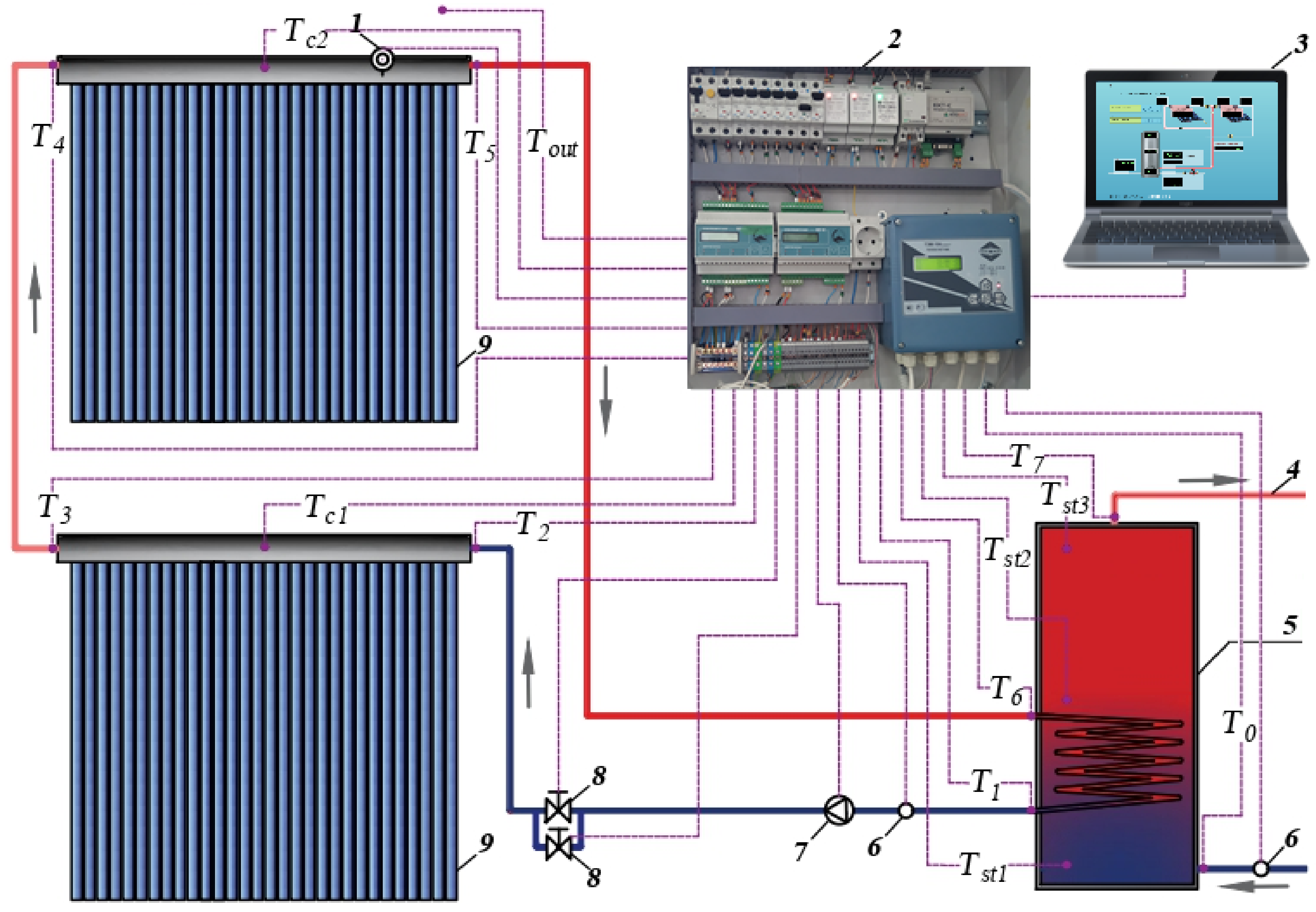
2. Materials and Methods

The following section describes materials and methods of the field and laboratory research on the performance of solar hot water systems during the winter season.
Every entrance of the apartment buildings in the Zhatay energy-efficient district in Yakutsk is equipped with hybrid hot water systems (HHWS) for year-round use (Figure 1 and Figure 2). A special room is built on top of a single-entrance residential building (Figure 1a) where the heating equipment and the photovoltaic (PV) system are located. Three groups of HHWS solar collectors and photovoltaic panels are installed on the roof of this room. In a three-entrance energy-efficient residential building (Figure 1b), photovoltaic panels of one PV system and nine groups of solar collectors of three HHWS are installed on the roof of the mechanical floor. PV systems supply electric energy to circulating pumps of hydraulic circuits of HHWS collectors and emergency lighting in residential buildings and the adjacent territories.
A field study of HHWS was performed for the single-entrance residential building located at 3 Komsomolskaya St. in Yakutsk. The system under study is equipped with a gas-fired boiler and three storage tanks with a capacity of 1000 L each (Figure 2a). Thermal energy is supplied from three groups of collectors located on the roof above the storage tanks (Figure 2b).
The design value of the annual solar fraction for the hot water systems in Yakutsk was 51%. The project included measurements of and control for the total natural gas consumption by three gas-fired boilers for heating, ventilation and hot water supply. Therefore, it was impossible to estimate the annual solar fraction and the system efficiency experimentally. In this regard, the software and hardware system were substantially improved. As can be seen from Figure 3, the gas-fired boiler was equipped with a heat meter to measure the heat input and output. Measurements were conducted every minute. The average integral hourly value of thermal energy generation was obtained using the trapezoidal method. The hourly values were then entered into a database and stored for three months.
Heat meters were installed in the same way in each of the three hydraulic circuits, as illustrated in Figure 3. The heating agent consumption and its temperature in each hydraulic circuit were measured every minute at the input and output of the respective storage tank. The data processing and the database creation were performed in the same manner. The consumption and temperature of cold water entering storage tank 1 and the consumption and temperature of the heating agent entering the heat exchangers of storage tanks 1, 2 and 3 from the respective hydraulic circuits of the collector groups were also measured every minute. The obtained data were converted into thermal energy by the heat meters. The consumption and temperature of hot water from storage tank No. 3 were measured continuously. The average hourly values were calculated by using the trapezoidal method. The readout time of all meters was synchronised.
In vitro studies of winter operation of the solar hot water system and prevention of the heating agent from night freezing in hydraulic circuits of the tube collectors were carried out on a pilot plant installed in the Kaftanchikovo village in the Tomsk region [24]. Photographs in Figure 4 illustrate the indoor and outdoor equipment of the solar hot water system.
In Figure 4a, one can see two tube collectors mounted southwards near the front at an angle of 47 degrees. One collector consists of 30 evacuated tubes 1.8 m long. The control panel with the data collection and processing unit is shown in Figure 4b.
Figure 4c is a photograph of a steel pipe inside the house with a three-phase circulating pump, heat meters connected to collectors and pressure sensors. The steel pipe and isolation valves provide both series and parallel flow of the heating agent to the collectors. Propylene glycol with a −30 °C freezing point is used as a heating media.
The heat-insulated hot water storage tank shown in Figure 4d has a capacity of 1000 L. Cold water pipes arranged at the bottom of the storage tank are equipped with a cold water meter with a pulse output and a temperature sensor.
The schematic circuit of the solar hot water system prototype is presented in Figure 5. The solar radiation sensor 1 is mounted on the upper part of the second collector manifold at an angle of 47 degrees. By request or using a given algorithm, control panel 2 with the data collection and processing unit provides the system operating modes and sends data to the server 3. Hot water from storage tank 5 is supplied through steel pipes 4. Flow meters 6 are used to measure the consumption of cold water and heating agent supplied by the circulating pump 7 to the hydraulic circuit of collectors. Running and auxiliary solenoid valves 8 control the modes of water circulation through collectors 9.
The amount of thermal energy supplied to the storage tank from the heating agent flowing in the hydraulic circuit is measured. The measurements are performed using a heat meter by the flow of the heating agent in the circulation circuit and outlet and inlet temperatures T1 and T6 of the heating agent.
The operation control for the circulating pump, heat meter and solenoid valves is performed by using a controller installed at the bottom left of the control panel. Another adjacent controller is used to maintain the parameters of T2, T3, T4, T5, Tst2, Tst3, Tout, Tin and T7.
A mnemonic diagram was developed for the solar hot water system installed in the Laboratory of the Research, Development and Production Facility “Application of energy-saving technologies” located in the Kaftanchikovo village. The mnemonic diagram enables control for all the operating parameters and remotely modifies the control parameters’ values. The data can be represented either graphically or in tabular form.
Control for the circulating pump operation under normal conditions includes comparing water temperatures Tst1 and Tc1 at the storage tank bottom and the centre of the first collector manifold, respectively. The circulating pump switches on and off, when the temperature difference reaches Tc1Tst1 = 10 °C and Tc1Tst1 = 5 °C, respectively. This provides efficient conversion of solar insolation into thermal energy in cloudy weather.
The interval between measurements of all parameters of the system can be 1, 2, 4, 8, 16 and 32 s; 1, 2, 4, 8, 16 and 32 min and 1 h. With the account of inertia of, for example, clamp-on resistance thermometers, the optimal measurement time was selected, which is 8 s.

3. Results and Discussion

Section 3.1 and Section 3.2 are devoted to measures against freezing the heating agent in hydraulic circuits of tube collectors and water in storage tanks. These chapters also describe measures to decrease the thermal performance of solar collectors during snowfall.
In Section 3.1, the results of the field study of the operating hot water systems in Yakutsk are discussed. Section 3.2 presents the experimental results obtained for the pilot plant for solar hot water supply in Tomsk, which proves the possibility of preventing the heating agent from freezing in hydraulic circuits and minimum water enthalpy drop in storage tanks.

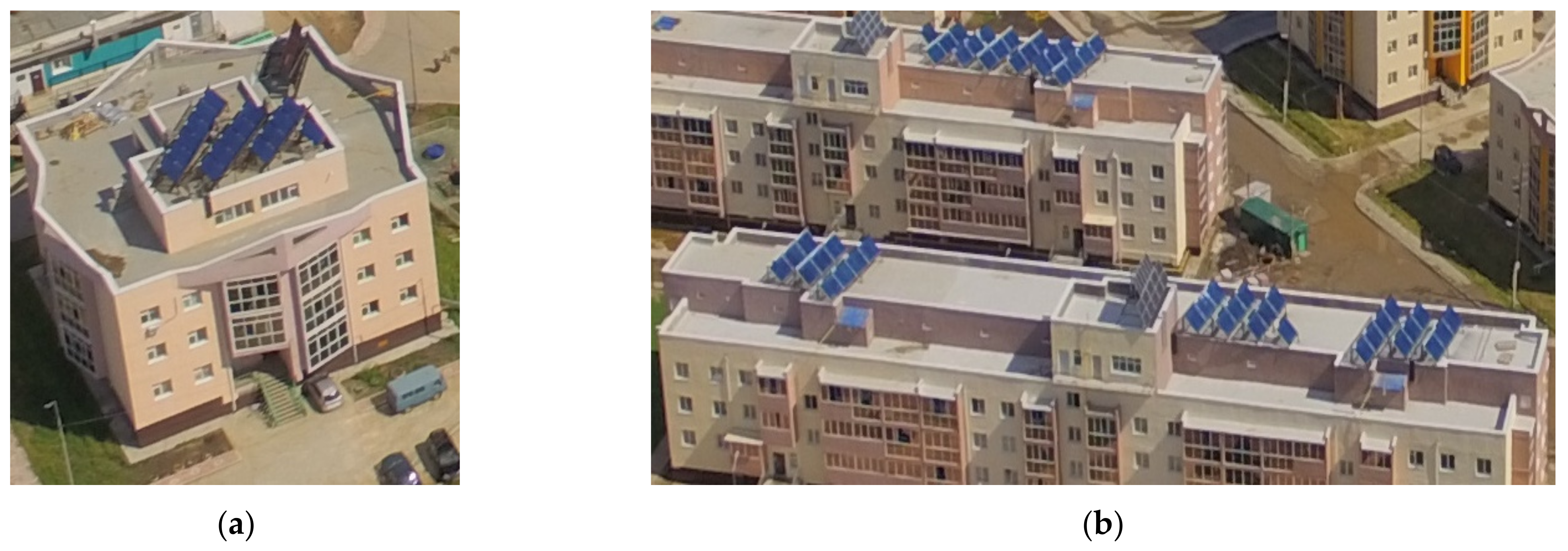
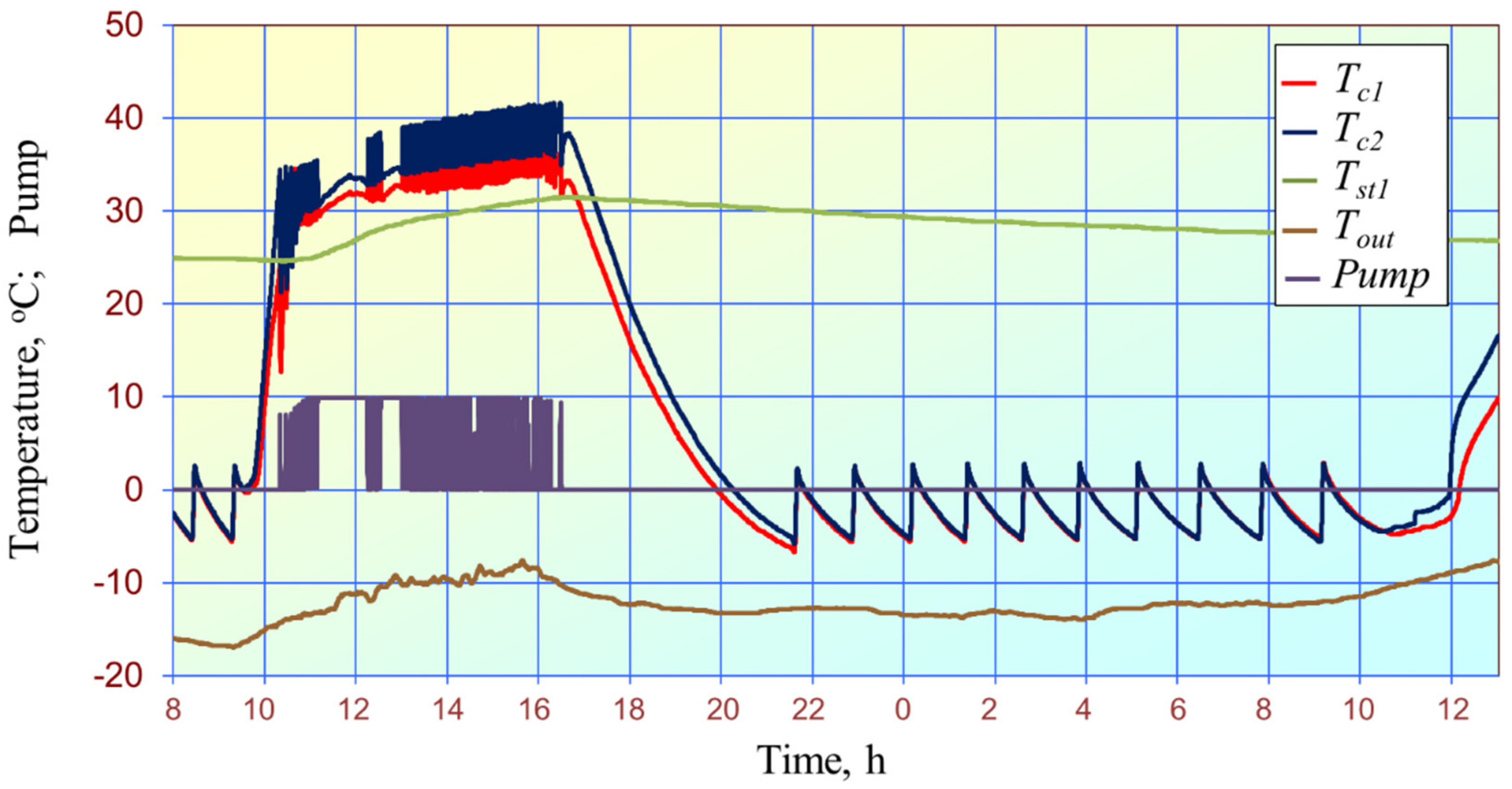
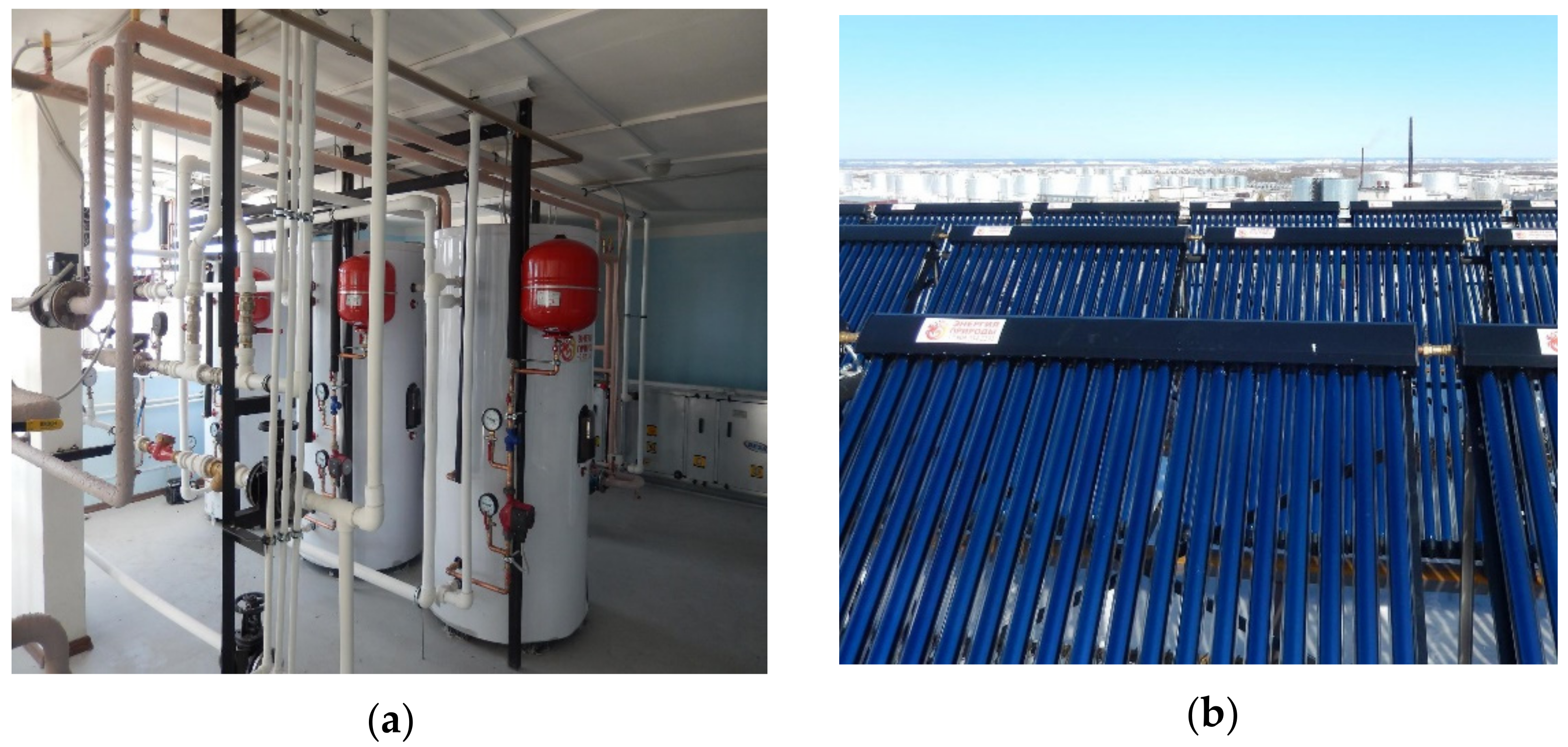
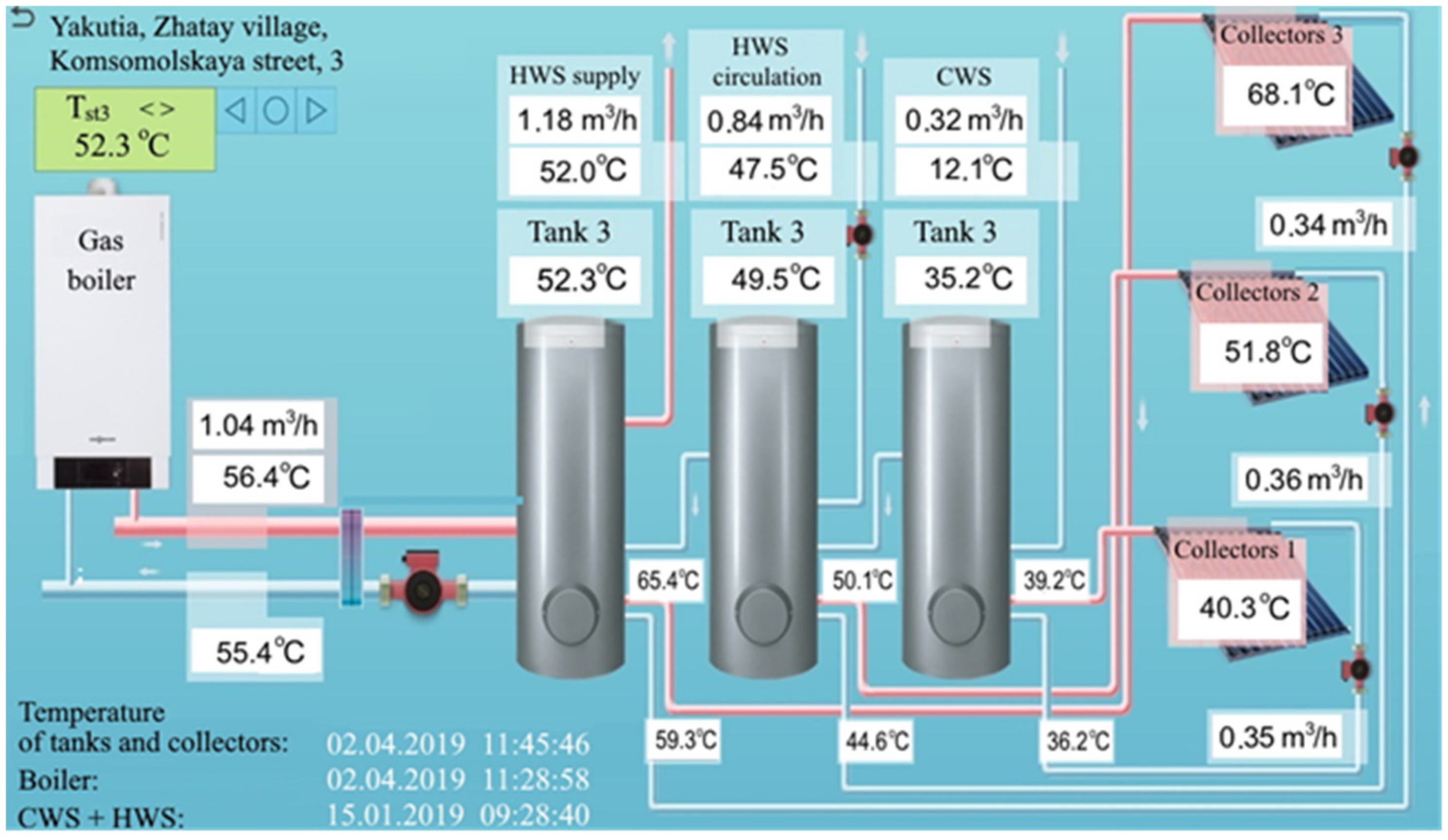
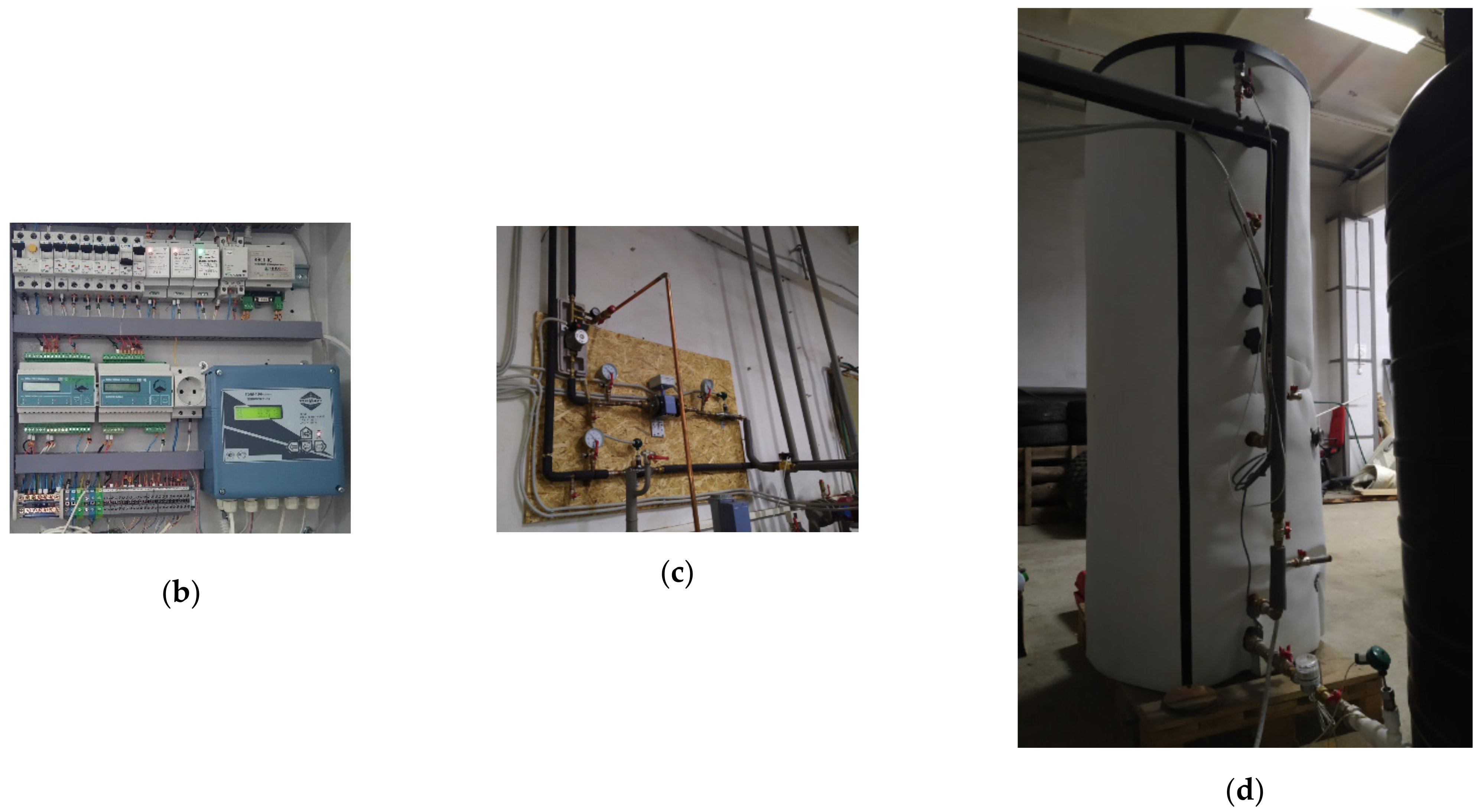
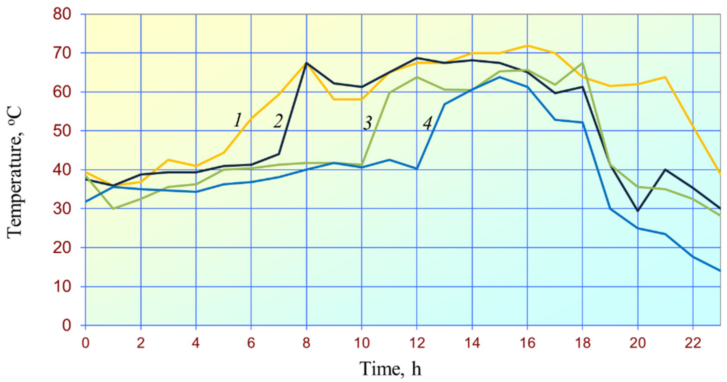
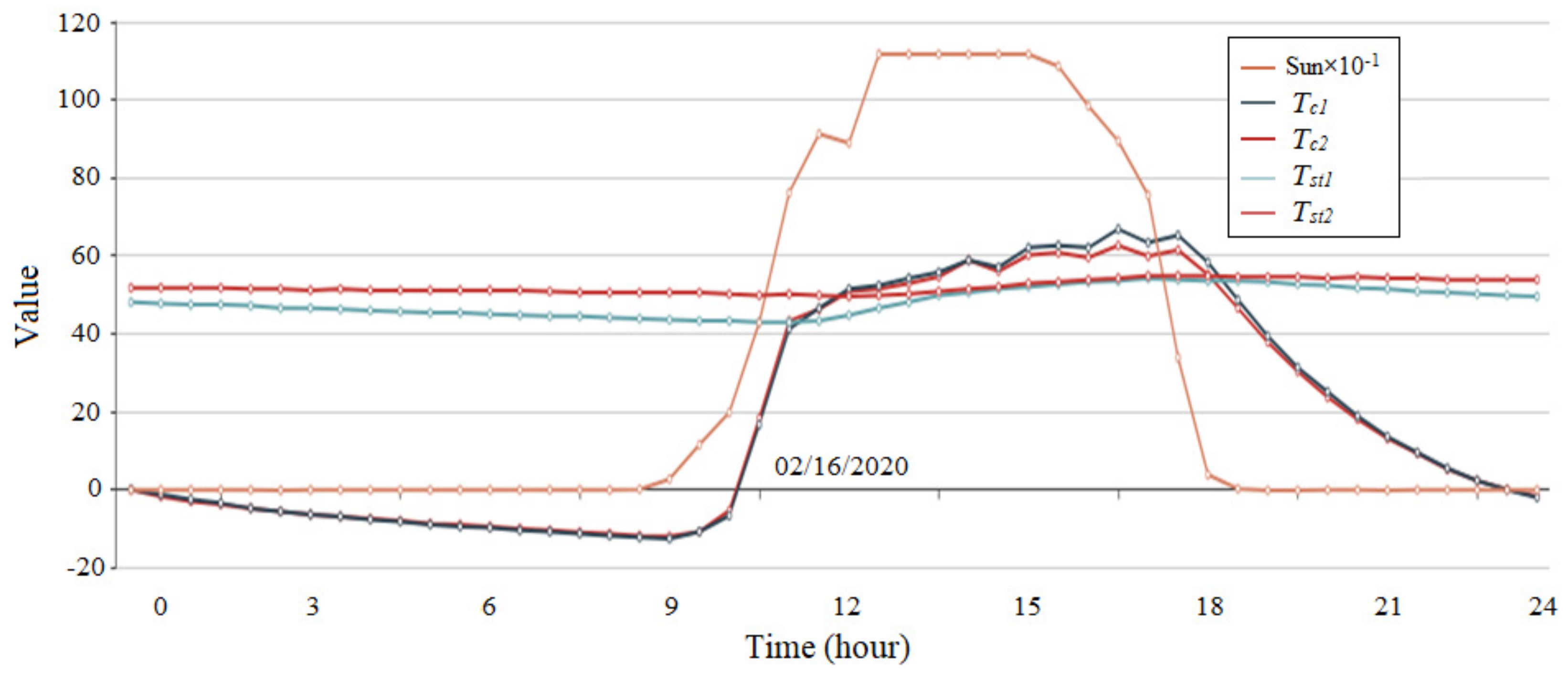
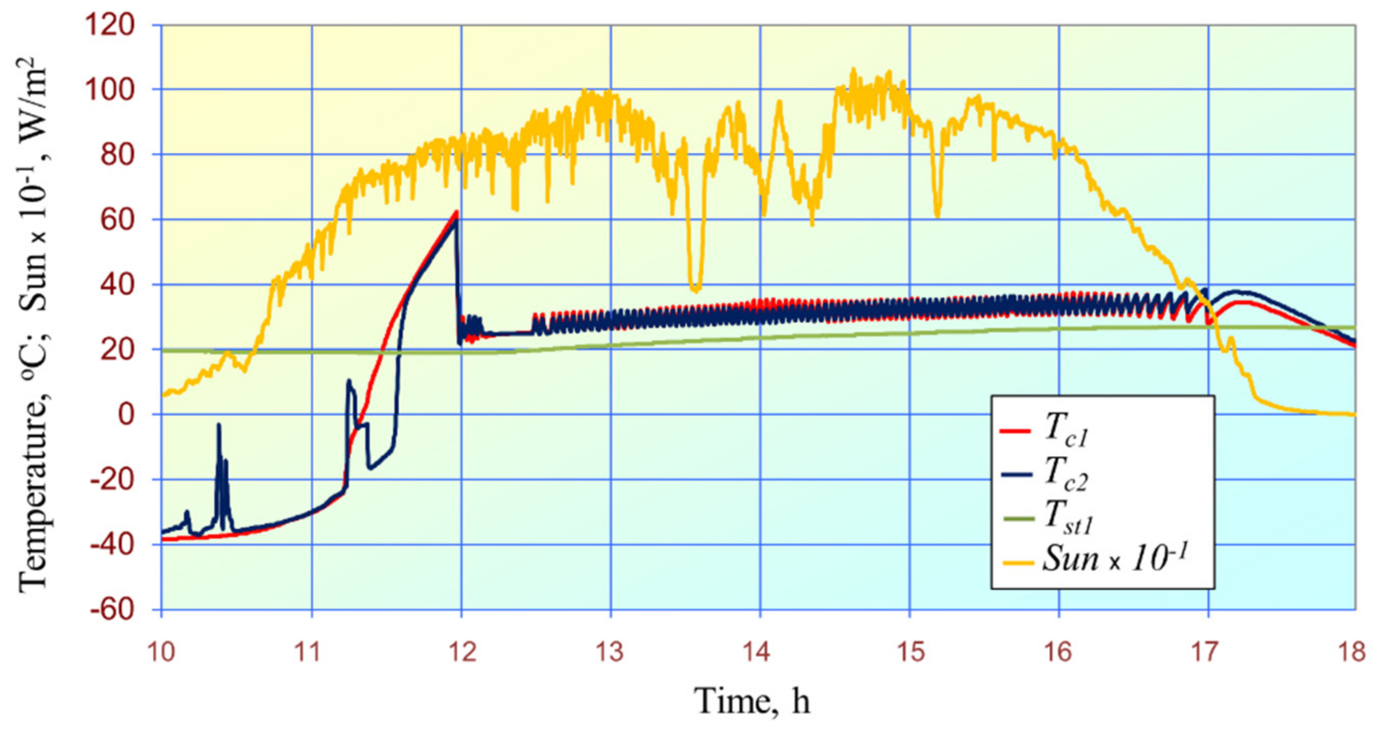
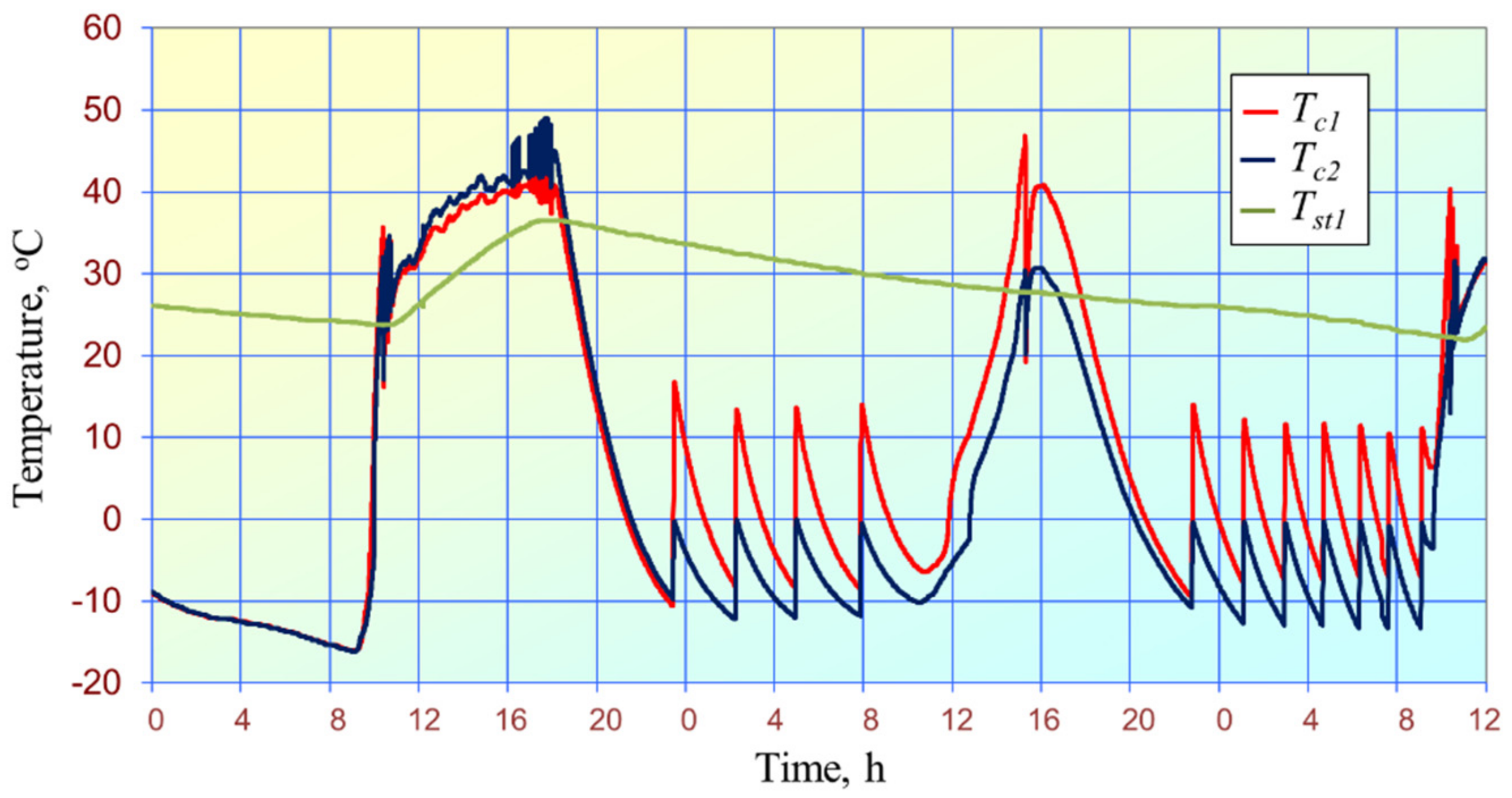
3.1. Results of Field Study in Yakutsk

In 2017–2019, the investigation was performed on the efficiency of solar energy installed in the energy-efficient building with one entrance (Komsomolskaya Street, Yakutsk) [23] and Vasilek kindergarten (Kasyanov Street, Zhatay) [22], both with embedded solar hot water systems. It was found that frost protection of the heating agent in the hydraulic circuit was provided by using propylene glycol with a −60 °C freezing point and its natural convection in the hydraulic circuit at night.
Figure 6 presents the temperature curves obtained in 2017 and 2018, according to which the night temperature of collector group 1 (see Figure 3) is always positive due to the natural convection in hydraulic circuits. The expensive low-freezing liquid in hydraulic circuits is necessary to prevent it from freezing below −60 °C.
In the recent research [23] on hourly hot water consumption (V1V2) during the day (see Figure 7), it was found that when water was not consumed (V1V2 = 0), the thermal energy that had been generated by the gas-fired boiler for 3 h was 2.6 times higher than the one required for compensation of thermal losses provided by the storage tank 3 (see Figure 3) and the hydraulic circuit of the hot water system.
Let us refer to Figure 3. Given that hot water returns from the hydraulic circuit to storage tank 2, the calculations performed in [23] are refined. When hot water is not consumed (V1V2 = 0), the thermal energy generated during 3 h is 2.2 times higher than that required to compensate for thermal losses provided by storage tanks 2 and 3, including the hydraulic circuit of the hot water system. It can be explained by the fact that natural convection in hydraulic circuits at night enables the additional thermal losses compensated by the thermal energy of the gas-fired boiler. Before, natural gas consumption was unprofitable, and hazardous emissions grew.
According to [23], in 2019, the solar fraction in the hot water system of the building with one entrance (3 Komsomolskaya Street, Yakutsk) was 28.69% instead of the design value of 51%. Therefore, this method of frost protection of the heating agent in the hydraulic circuit is rather energy-consuming but allows using water as a heating media.
Based on the above data, the selected method for preventing the heating agent from freezing in circulation circuits is the most energy-consuming. Still, even water can serve as a heating media in this case. However, it is possible that water in the coldest storage tank 1 could freeze in December and January. The solar activity in these months in Yakutsk is the lowest [26], namely 9 h in December and 19 h in January. Therefore, the temperature in the storage tank approaches that of cold water supplied (~12 °C). In these months, the decrease in the water temperature at night is induced by thermal losses from the surface of the storage tank and hydraulic circuit due to the natural convection of the heating agent.
As shown from Figure 8, the night temperature of collectors reduces to the ambient temperature after switching off a heating agent valve. The water temperature in the storage tank lowers due to only thermal energy losses from its surface. In this case, thermal energy losses from the external steel pipes with the heating agent, including the collector manifolds, are reduced to the enthalpy decrease. Solar energy compensates for this enthalpy decrease after sunrise.
In Figure 7, complete frost protection of the heating agent in collectors group 1 and water in storage tank 1 can be provided by switching off this hydraulic circuit in December and January. Such a solution is substantiated by a short sunshine duration in these months, the absence of water cooling due to the natural convection at night and the electric energy consumption by the circulating pump of this hydraulic circuit.
However, the problem of heating agent frost protection in the negative temperature conditions and with minimum additional losses was solved only in Tomsk.

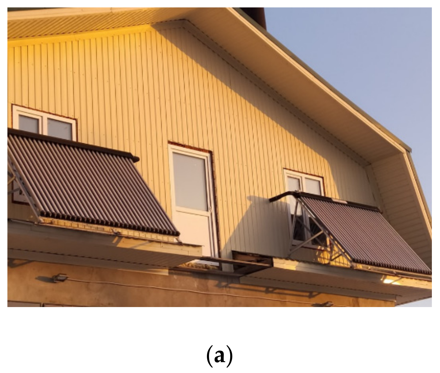
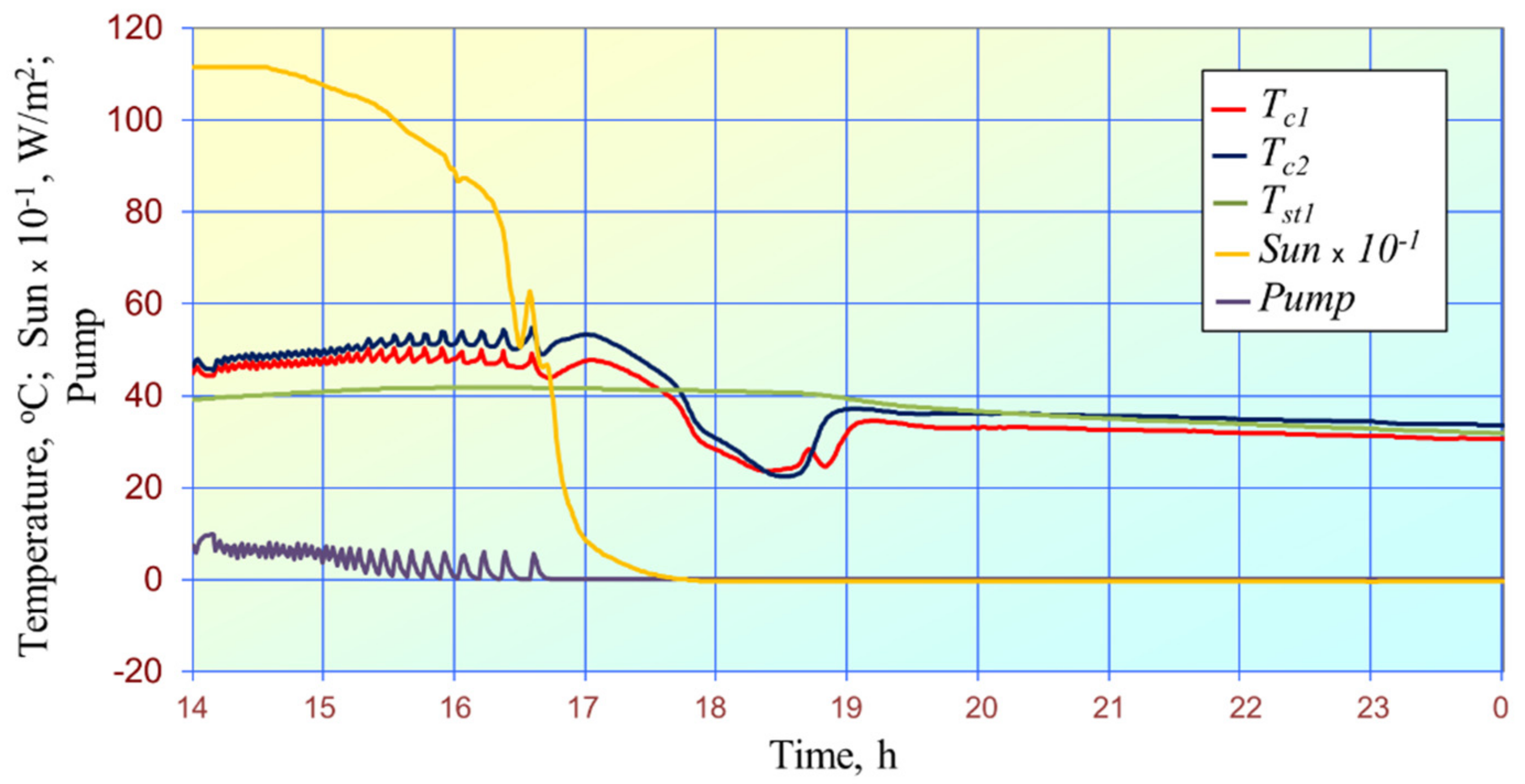
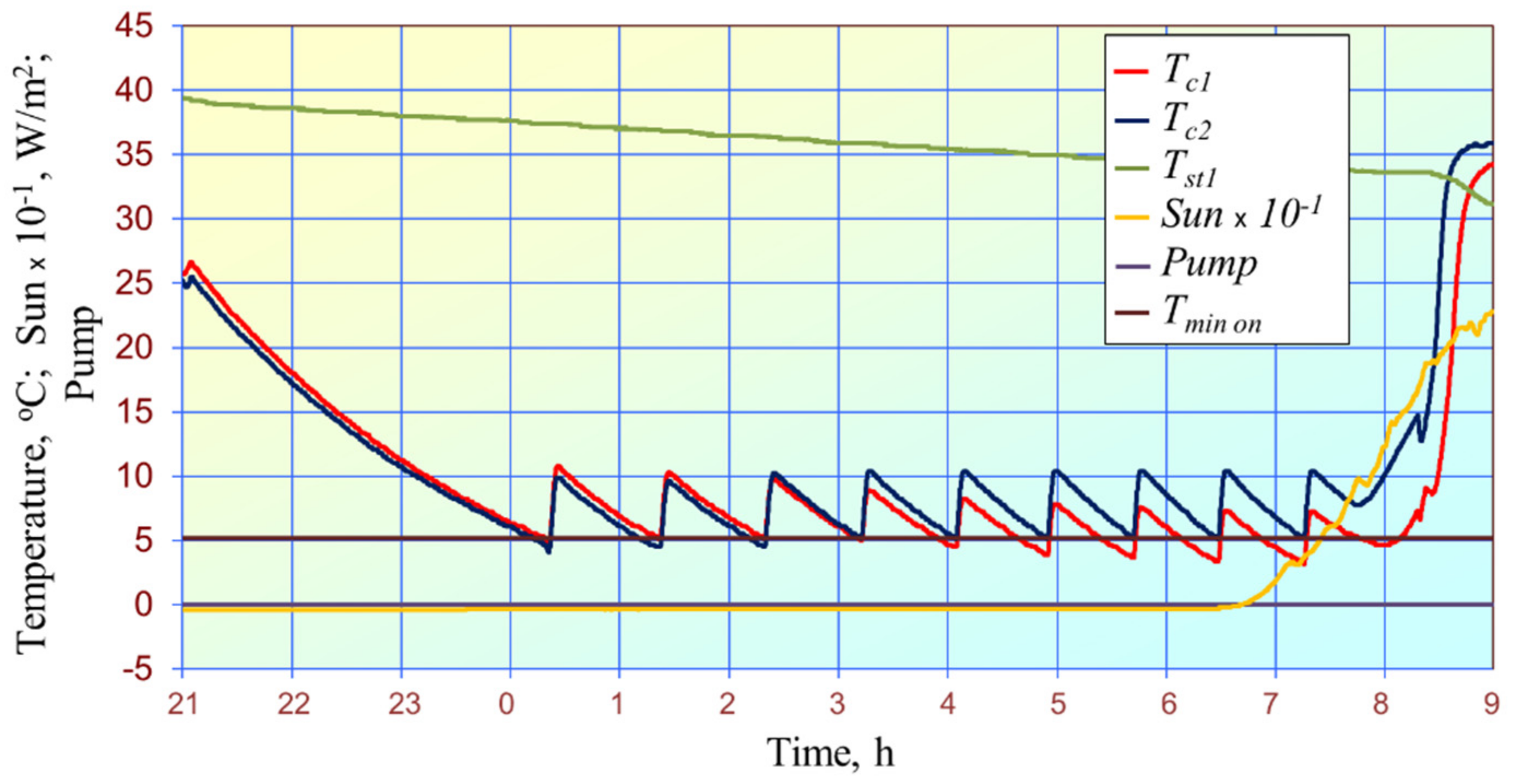
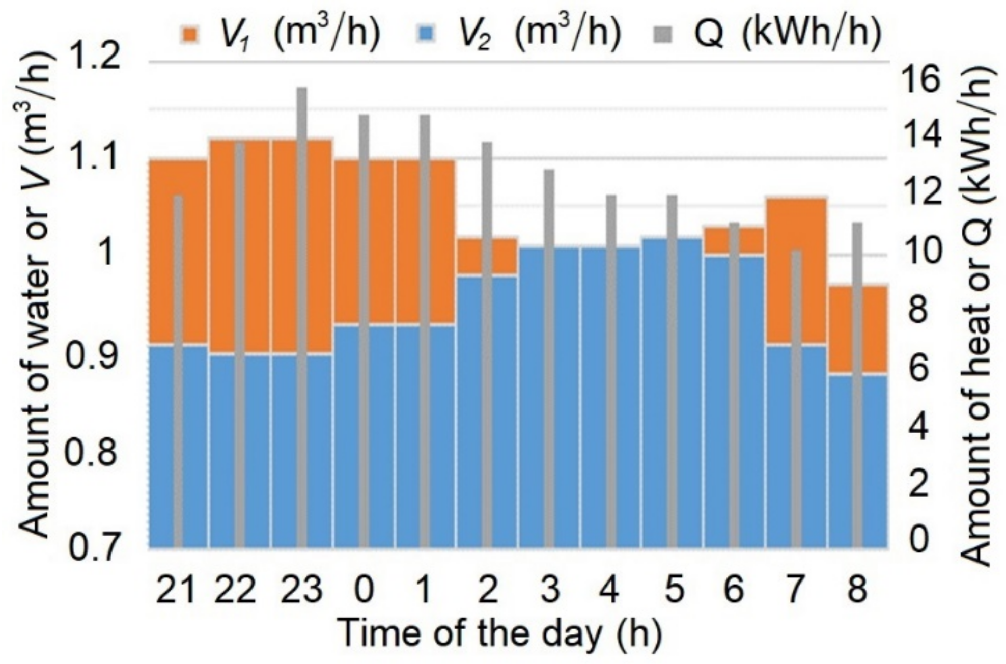
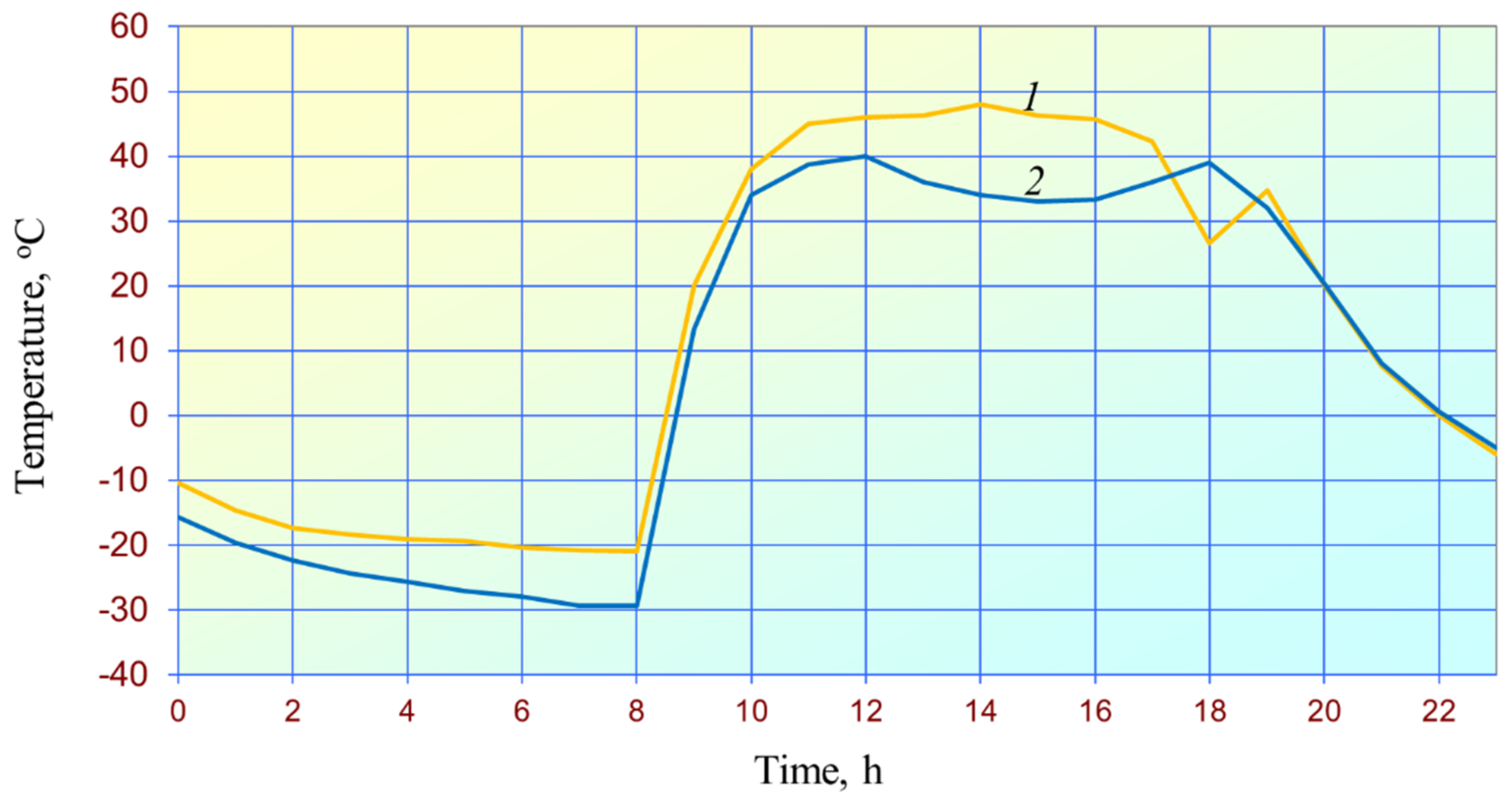
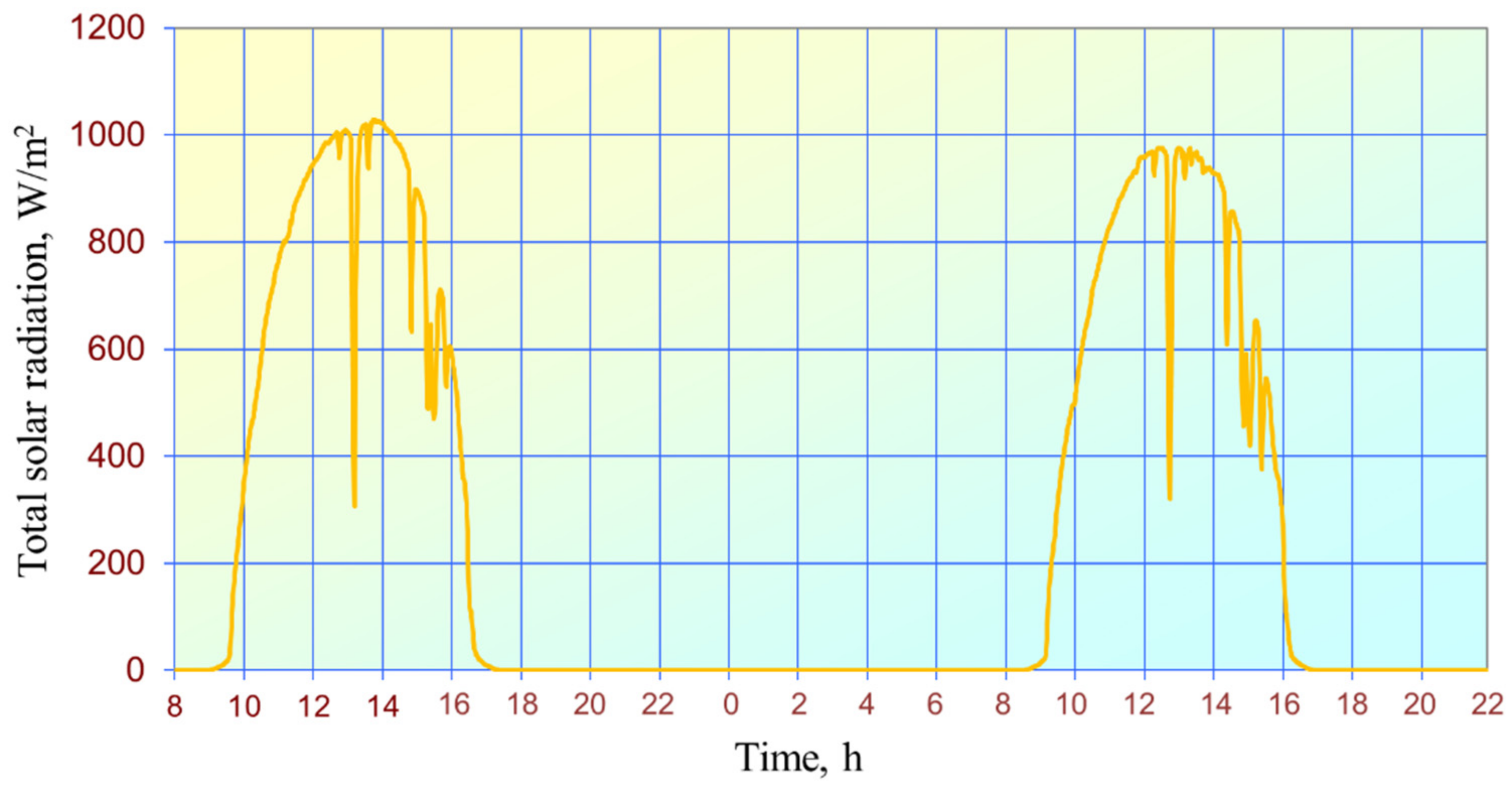
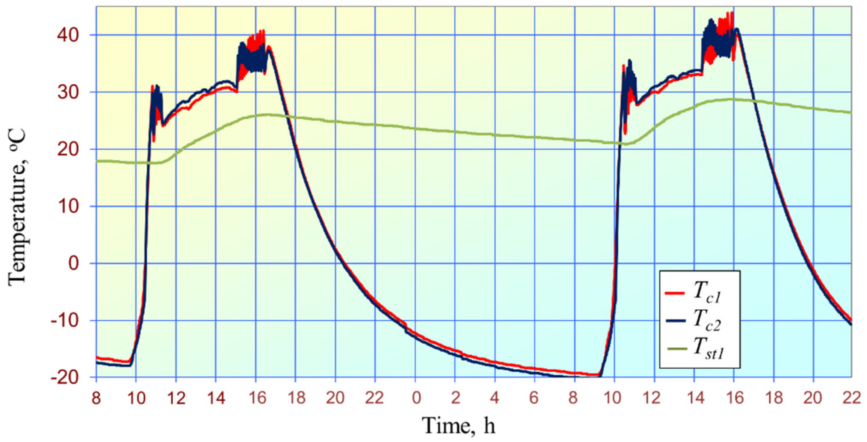
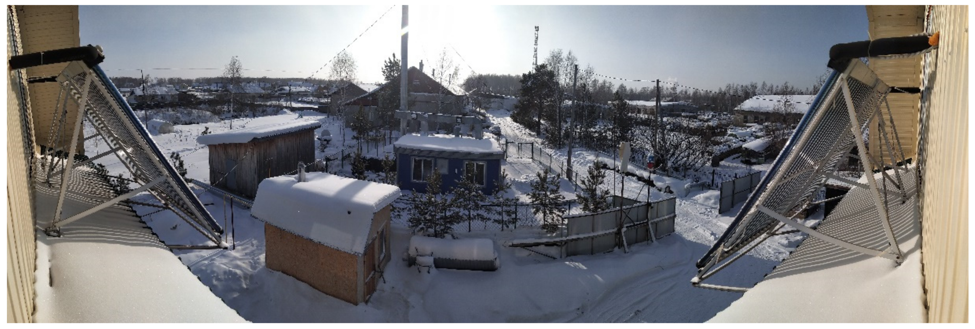
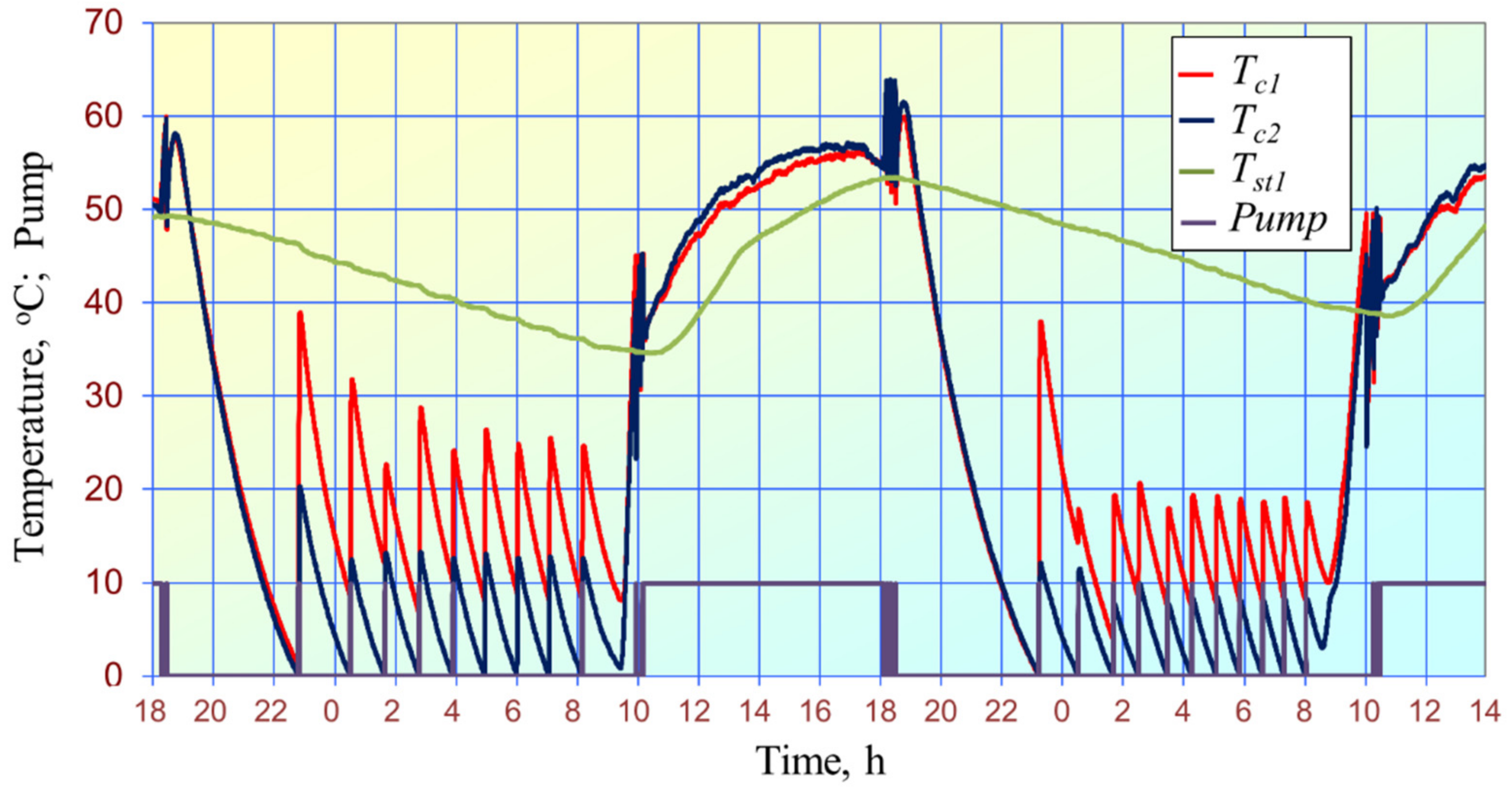
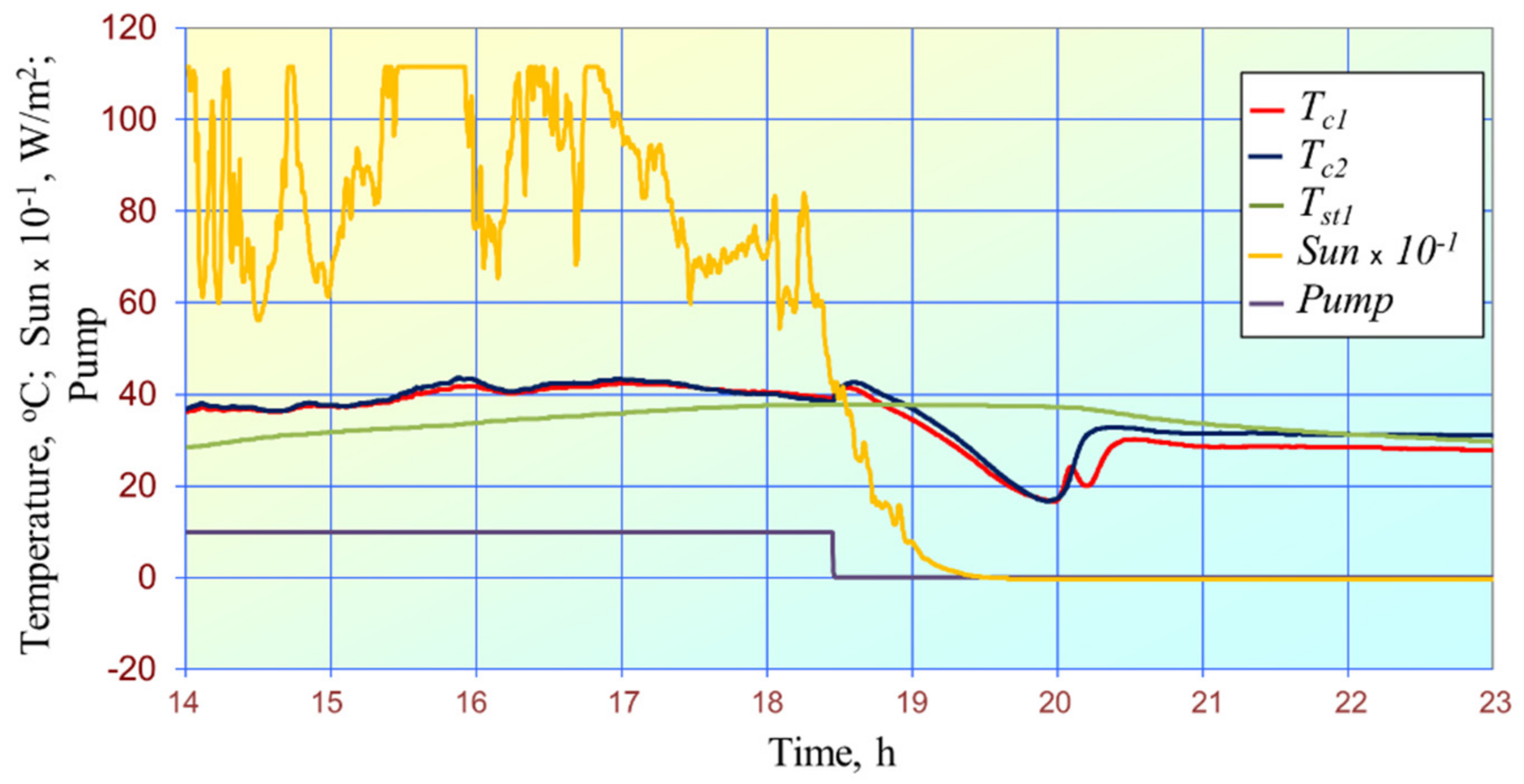
3.2. Results of Experimental Research in Tomsk

By using the pilot plant of solar hot water supply presented in Figure 5, Figure 6 and Figure 7, in the study [23], it was found that on 2–4 November 2019, thermal losses from the hydraulic circuit with the natural convection of the heating agent were more than 2.2 times higher than that from the storage tank surface. It was proposed to use a solenoid valve, which helped eliminate the natural convection and additional thermal losses from the hydraulic circuit of tube collectors. The use of the solenoid valve was substantiated because, unlike an inverted valve, it possessed a low hydraulic resistance and could be easily controlled. Therefore, the software and hardware were selected such as to control the solenoid valve.
Maraj et al. [27] show that under the Mediterranean climate conditions, the annual thermal losses from the solar circuit are 34 kWh, whereas, from the storage tank surface, these losses are 302 kWh, which is 8.9 times higher. According to these data, a solar water heating system without a solenoid valve can be readily used in southern territories. As for northern regions, such systems must be equipped with solenoid valves if a hot water storage tank is placed below collectors (see Figure 5).
A typical daily change in the operating parameters of the solar hot water system with the solenoid valve is presented in Figure 9. The measurements are carried out with the interval of 1 min using average parameter values obtained after each 30 min.
At night, the temperature difference grows between the central and bottom parts Tst2 and Tst1 of the storage tank. The temperature rise of collectors occurs after sunrise. When collector 1 achieves the temperature difference of Tc1Tst1 = 10 °C, the circulating pump switches on, and thermal energy is supplied to the storage tank. The maximum temperature difference of Tst2Tst1 = 8.1 °C decreases, and after about 3 h, this difference disappears, viz. Tst2 = Tst1 until the circulation of the heating agent stops. Then, at 18:49, collectors are cooled, and the temperature difference Tst2Tst1 grows. The data presented in Figure 9 obtained after every 30 min do not allow us to estimate the change in the operating parameters correctly.
Figure 10 and Figure 11 demonstrate the correlations obtained at lower outside temperatures of about −20 °C on partly sunny days. Measurements are performed with an interval of 8 s. A drastic decrease in solar radiation on collectors observed in Figure 10 occurs at about 13 h. It is caused by a shadow from the chimney of the gas boiler house, as shown in Figure 12. In this Figure, one can see this shadow at the left.
Figure 11 on the left shows the temperature fluctuations in collectors on 26 November 2020. These fluctuations occur after the opening of the solenoid valve and the first switching on of the circulating pump at about 11 a.m. In the afternoon, the temperature fluctuations in collectors are observed between 15:00 and 16:30. In this Figure, the same temperature fluctuations are observed (right), caused by an insufficient amount of solar radiation in the morning and the evening and automatic control for the circulating pump. When the daytime solar radiation is sufficient, the circulating pump does not switch off. The collector temperature gradually grows along with the temperature at the bottom of the storage tank. At night, the collector manifolds and the outdoor equipment of the solar hot water system are cooled down to the outside temperature.
ECO-30 propylene glycol is a low-freezing heating agent with an operating temperature of up to −30 °C. What are the operating parameters of the solar hot water system when the outside temperature is below −30 °C?
The analysis of such a situation and the experimental data includes the description of the real pipe arrangement in the hydraulic circuit. The circulating pump delivers the heating agent from the storage tank to collector 1 (see Figure 4a and Figure 5, right) through the feeding pipe. The latter parts are located in heated space, unheated roof space and outside the house. From collector 2 (Figure 4a, left), the heating agent flows in the outer part of the outlet pipe, unheated roof space and heated space. Collectors 1 and 2 are connected with a U-shaped pipe. Its upper parts are in contact with the outside air, the central parts are in unheated roof space, and the bottom part locates in a heated area (see Figure 4c).
The daily experiment data are presented in Figure 13 (25 January 2021). According to [28], the outside temperature in Tomsk was −44 °C at night, −41 °C in the morning and −38 °C in the evening. The day was cloudy. Indeed, the heating agent froze in the outer parts of the hydraulic circuit.
After sunrise, the temperature of collectors slowly rose to about −30 °C (Figure 13, on the left) due to the phase transition of the heating agent in the collector manifolds. At 11:02:32, a sharp rise in the temperature occurred in both collectors and remained until 11:14:48. The temperature growth in collector 1 then slowed down, whereas, in collector 2, it lowered and then slowly rose. This was due to the natural convection of the heating agent, which entered the manifold from the U-shaped steel pipe mounted between collectors. When the temperature of the collector 1 reached 28.4 °C, which was 10 °C higher than the temperature at the bottom of the storage tank, the circulating pump switched on (at 11:33:08). However, the pump power was insufficient for circulating the whole volume of the jelly heating agent, which plugs the U-shaped pipe between collectors. Nevertheless, the hearting agent passed through collectors in a minimal amount, and the temperature of collectors rose to 60 °C. The temperature drop indicated that the heating agent consumption in the hydraulic circuit occurred in normal conditions.
A periodic switching on and off of the circulating pump within the specified temperature range higher than the freezing point is the simplest way to protect the heating agent from freezing.
When the collectors cool down at night, their temperatures can vary. As presented in Figure 14, the automatic control for the circulating pump lowers the night temperature of collector 2 below −10.1 °C. The temperature of collector 2 is significantly higher than the specified level of 0.1 °C. Such circulating pump control does not allow maintaining the temperature in collector 2 at the level of no lower than −10.1 °C, below which it must not be cooled.
Figure 15 plots the change in the operating parameters of the hot water system at nighttime and daytime during the circulating pump control. At night, the pump switches on and off when the temperature of collector 2 is 0 and 10 °C, respectively. The pump operation in Figure 15 is as follows. When the pump switches on, the system records the value of 10, and when it switches off, it records zero.
In such operating conditions, the temperature of collector 2 cannot decrease below 0 °C. However, its upper level exceeds 10 °C due to the thermal inertia from both collectors.
The study results on the natural convection in the hydraulic circuit with the open solenoid valve are presented in Figure 16 and Figure 17. As the collector cools down, the water temperature in the central part of the storage tank grows compared to its bottom (see Figure 9). Therefore, the heating agent flows in the reverse direction, unlike in the case of the circulating pump operation. It is important to note that at the beginning of the natural convection, the temperature of collectors 1 and 2 is almost the same and slowly grows by 5 °C at the same rate. This mechanism can be effectively used in the proposed method of the heating agent frost protection with minimised thermal losses of water enthalpy drop in storage tanks.
Essentially, once the lowest temperature of the collector 2 is achieved, e.g., Tc2 = 5 °C, as depicted in Figure 18, the electric energy is supplied to the solenoid valve and enables its opening. The occurring natural convection causes the temperature rise similar for both collectors. When the temperature of collector 2 is 10 °C, the solenoid valve closes, and collectors cool down again; the opening and closing of the solenoid valve repeat. The cooling of the more heated collector 2 slows down after sunrise. At the same time, its temperature does not reach 5 °C, and after its minimum value of 8.1 °C, it increases due to solar radiation.
Since the heating agent flows in the reverse direction, unlike in the case of the circulating pump operation, the temperature of collector 1 decreases when the solenoid valve opens or closes. In this case, the lowest temperature decreases below the specified level of 5 °C and reaches 3.6 °C at the time point of the final opening of the solenoid valve.
A short-time single pump switching on after three openings of the solenoid valve can eliminate this drawback. The pump should be switched off when the temperature of collector 1 is 2 °C lower than the specified upper level of 10 °C required for the circulating pump control.
As shown in Figure 19, when the temperature of the solenoid valve opening is decreased to −5 °C and the collectors cooling time is increased (to more than 1 h), the use of the circulating pump is not required.
Figure 20 demonstrates that the solenoid valve’s openings and closures depend on the outdoor air temperature and the pre-set temperature for its opening.
The obtained results confirm the possibility of control for the operating modes of solar hot water systems at night with the prevention of heating agents from freezing and minimum thermal losses from hydraulic circuits of collectors.

4. Discussion

The present research shows that during the year-round operation of solar hot water systems in northern regions of Russia (Yakutsk), freezing of the heating agent does not occur in hydraulic circuits of collectors due to its natural convection with the water enthalpy drop in the storage tanks (see Figure 6). Propylene glycol with a −60 °C freezing point is used to protect the heating agent from freezing in emergencies. However, at low outside temperatures and natural convection of the cooled heating agent at night, water freezing can occur in the storage tank supplied with cold water. Moreover, this engineering solution leads to additional losses of water enthalpy in storage tanks [24]. The study proposes to eliminate these losses by using the solenoid valve. In this case, the temperature of the heating agent in collectors decreases to the outside temperature (see Figure 11). If the freezing point of the selected heating agent is higher than the outside temperature, it can freeze at night (see Figure 13).
In order to avoid the heating agent freezing in the hydraulic circuit of collectors, it is expedient to use a cyclic switching of the circulating pump when the temperature in the last collector reaches the specified lower level; the circulating pump switches on when the temperature in the last collector reaches the specified level. In this case, additional losses of water enthalpy in the storage tank are also observed owing to the higher temperature of collector 1.
While studying the initial stage of the natural convection in the hydraulic circuit (Figure 16 and Figure 17), when the temperature of collectors slowly grows by ~5 °C, the idea emerged to implement the third method to prevent the heating agent from freezing. This method is more energy efficient (see Figure 18, Figure 19 and Figure 20) and provides an automatic opening of the solenoid valve when the night temperature in the last collector reaches the specified lower level. Automatic closure of the solenoid valve occurs when the temperature in the last collector travels up to the specified upper level required for the circulating pump control. The difference between these temperatures does not exceed 5 °C.
Using a circulation pump with frequency regulation of the speed in the collectors’ hydraulic circuit in the Kaftanchikovo village will further improve the efficiency of insolation conversion by the collectors in the morning, before sunset and on cloudy days. The use of this frequency-controlled pump in conjunction with a solenoid valve will ensure the reliability of the operating modes of the hydraulic circuit of the collectors at night at outdoor temperatures below the freezing point of the coolant.
The distance between the collectors is 4.14 m, which is the main limitation for the more efficient operation of the solar hot water system since significant heat losses occur in this area. It is planned to place another collector between the existing collectors and use additional thermal energy in spring and summer to evaporate sap, dry berries, mushrooms, etc.
The future study will concern the following issues:
-
Modelling of solar radiation to define its hourly values based on the data obtained from Tomsk weather station;
-
Development of a mathematical model and analysis of the annual thermal energy losses in the hydraulic circuit of collectors; a comparison of the calculation results with the experimental data obtained from the solar hot water system in the Kaftanchikovo village;
-
Development of a mathematical model and implementation of the frequency control for the engine speed of the circulating pump, depending on the solar radiation intensity.

5. Conclusions

The way to achieve the maximum solar fraction in solar hot water supply systems for the northern climate is proposed by eliminating the natural convection of the coolant in the circulation circuits of the collectors at night when the system is operating above the freezing point of the coolant. This method is applicable when using an expensive coolant in a system with a freezing point below the lowest air temperature in a particular northern area.
At outdoor air temperatures below the freezing point of the coolant, a method for controlling collector temperatures is proposed, which presumes automatically opening the solenoid valve at night when the temperature of the collector reaches a low level. In this case, natural convection of the coolant occurs, and the collectors slowly warm up. The solenoid valve closes automatically when the collector temperature reaches 5 °C above the set low-temperature level. This control method allows the use of cheaper coolants.
The combined use of the first and second methods makes it possible to achieve the maximum solar fraction in hybrid solar hot water systems. It is achieved when operating above the freezing point of the coolant to minimise the loss of water enthalpy from the storage tanks at night during short periods of system operation below the freezing point of the coolant.

Author Contributions

Conceptualization, N.T. and S.B.; methodology, N.T.; software, A.S. and Y.K.; validation, A.S.; formal analysis, A.T.; investigation, N.T., A.S. and Y.K.; resources, N.T. and S.B.; data curation, Y.K. and A.T.; writing—original draft preparation, N.T.; writing—review and editing, S.B.; visualization, Y.K. and A.T.; supervision, N.T.; project administration, N.T.; funding acquisition, S.B. All authors have read and agreed to the published version of the manuscript.

Funding

This research was funded by Tomsk Polytechnic University under development program [Priority 2030], and the APC was funded by TPU development program.

Informed Consent Statement

Not applicable.

Acknowledgments

This research was supported by the development program of Tomsk Polytechnic University.

Conflicts of Interest

The authors declare no conflict of interest.

References

  1. Tcvetkov, P. Climate Policy Imbalance in the Energy Sector: Time to Focus on the Value of CO2 Utilisation. Energies 2021, 14, 411. [Google Scholar] [CrossRef]
  2. Strielkowski, W.; Sherstobitova, A.; Rovny, P.; Evteeva, T. Increasing Energy Efficiency and Modernization of Energy Systems in Russia: A Review. Energies 2021, 14, 3164. [Google Scholar] [CrossRef]
  3. Khan, A.M.; Osińska, M. How to Predict Energy Consumption in BRICS Countries? Energies 2021, 14, 2749. [Google Scholar] [CrossRef]
  4. Qin, Z.; Ozturk, I. Renewable and Non-Renewable Energy Consumption in BRICS: Assessing the Dynamic Linkage between Foreign Capital Inflows and Energy Consumption. Energies 2021, 14, 2974. [Google Scholar] [CrossRef]
  5. Karacan, R.; Mukhtarov, S.; Barıs, I.; Isleyen, A.; Yardımcı, M.E. The Impact of Oil Price on Transition toward Renewable Energy Consumption? Evidence from Russia. Energies 2021, 14, 2947. [Google Scholar] [CrossRef]
  6. Brazovskaia, V.; Gutman, S.; Zaytsev, A. Potential Impact of Renewable Energy on the Sustainable Development of Russian Arctic Territories. Energies 2021, 14, 3691. [Google Scholar] [CrossRef]
  7. Fischer, R.; Elfgren, E.; Toffolo, A. Energy Supply Potentials in the Northern Counties of Finland, Norway and Sweden towards Sustainable Nordic Electricity and Heating Sectors: A Review. Energies 2018, 11, 751. [Google Scholar] [CrossRef] [Green Version]
  8. Swenson, R. The Solarevolution: Much More with Way Less, Right Now—The Disruptive Shift to Renewables. Energies 2016, 9, 676. [Google Scholar] [CrossRef] [Green Version]
  9. Haukkala, T. Does the sun shine in the High North? Vested interests as a barrier to solar energy deployment in Finland. Energy Res. Soc. Sci. 2015, 6, 50–58. [Google Scholar] [CrossRef]
  10. Wei, S.; Tien, P.W.; Calautit, J.K.; Wu, Y.; Boukhanouf, R. Vision-based detection and prediction of equipment heat gains in commercial office buildings using a deep learning method. Appl. Energy 2020, 277, 115506. [Google Scholar] [CrossRef]
  11. Abikoye, B.; Čuček, L.; Isafiade, A.J.; Kravanja, Z. Synthesis of solar thermal network for domestic heat utilisation. Chem. Eng. Trans. 2019, 76, 1015–1020. [Google Scholar] [CrossRef]
  12. Canale, L.; Di Fazio, A.R.; Russo, M.; Frattolillo, A.; Dell’Isola, M. An Overview on Functional Integration of Hybrid Renewable Energy Systems in Multi-Energy Buildings. Energies 2021, 14, 1078. [Google Scholar] [CrossRef]
  13. Porras-Prieto, C.J.; Benedicto-Schönemann, S.; Mazarrón, F.R.; Benavente, R.M. Profitability Variations of a Solar System with an Evacuated Tube Collector According to Schedules and Frequency of Hot Water Demand. Energies 2016, 9, 1053. [Google Scholar] [CrossRef] [Green Version]
  14. Popsueva, V.; Lopez, A.F.O.; Kosinska, A.; Nikolaev, O.; Balakin, B.V. Field Study on the Thermal Performance of Vacuum Tube Solar Collectors in the Climate Conditions of Western Norway. Energies 2021, 14, 2745. [Google Scholar] [CrossRef]
  15. Peña-Ramos, J.A.; Bagus, P.; Amirov-Belova, D. The North Caucasus Region as a Blind Spot in the “European Green Deal”: Energy Supply Security and Energy Superpower Russia. Energies 2021, 14, 17. [Google Scholar] [CrossRef]
  16. Decree of the President of the Russian Federation Dated 01.12.2016 No. 642 “On the Strategy of Scientific and Technological Development of the Russian Federation” (As Amended by the Decree of the President of the Russian Federation Dated 15.03.2021 No. 143). Available online: http://kremlin.ru/acts/bank/41449 (accessed on 20 May 2021).
  17. Energy Strategy of the Russian Federation until 2035. Approved by the Order of the Government of the Russian Federation Dated 9 June, 2020 No. 1523-r. Available online: https://minenergo.gov.ru/node/1026 (accessed on 9 June 2021).
  18. Gaweł, B.; Pali’ nski, A. Long-Term Natural Gas Consumption Forecasting Based on Analog Method and Fuzzy Decision Tree. Energies 2021, 14, 4905. [Google Scholar] [CrossRef]
  19. Cannone, S.F.; Lanzini, A.; Santarelli, M. A Review on CO2 Capture Technologies with Focus on CO2-Enhanced Methane Recovery from Hydrates. Energies 2021, 14, 387. [Google Scholar] [CrossRef]
  20. Kopteva, A.; Kalimullin, L.; Tcvetkov, P.; Soares, A. Prospects and Obstacles for Green Hydrogen Production in Russia. Energies 2021, 14, 718. [Google Scholar] [CrossRef]
  21. Seregin, A.I. Energy efficient town block in the far north conditions. Experience from the Republic of Sakha (Yakutia). Energy Sav. 2020, 8, 12–15. Available online: https://www.abok.ru/for_spec/articles.php?nid=7683 (accessed on 8 January 2021).
  22. Krivoshein, Y.O.; Tolstykh, A.V.; Tsvetkov, N.A.; Khutornoy, A.N. Efficiency of dual hot water systems with the use of solar evacuated tube collectors in the Northern territories. IOP Conf. Ser. Earth Environ. Sci. 2020, 408, 012011. [Google Scholar] [CrossRef] [Green Version]
  23. Tsvetkov, N.A.; Krivoshein, Y.O.; Khutornoi, A.N.; Boldyryev, S.; Petrova, A.V. Development of the Computer-Aided Application for the Use of Solar Energy in the Hot Water Supply System of Russian Permafrost Regions. Chem. Eng. Trans. 2020, 81, 943–948. [Google Scholar] [CrossRef]
  24. Tsvetkov, N.A.; Krivoshein, U.O.; Tolstykh, A.V.; Khutornoi, A.N.; Boldyryev, S. The calculation of solar energy used by hot water systems in permafrost region: An experimental case study for Yakutia. Energy 2020, 210, 118577. [Google Scholar] [CrossRef]
  25. Prokhorov, S.V.; Krivoshein, Y.O.; Shilin, A.A. Automatic Control of Hot Water Supply System on Solar Collectors (Conference Paper). In Proceedings of the International Multi-Conference on Industrial Engineering and Modern Technologies, FarEastCon 2019, Vladivostok, Russia, 1–4 October 2019. Category Number CFP19M35-ART; The Code 156113. [Google Scholar] [CrossRef]
  26. Climate of Russia. Wikipedia. Available online: https://ru.wikipedia.org/wiki/Климат_Рoссии (accessed on 6 August 2021).
  27. Maraj, A.; Londo, A.; Gebremedhin, A.; First, C. Energy performance analysis of a forced circulation solar water heating system equipped with a heat pipe evacuated tube collector under the Mediterranean climate conditions. Renew. Energy 2019, 140, 874–883. [Google Scholar] [CrossRef]
  28. Tomsk Weather Archives. Available online: https://pogoda.vtomske.ru/tomsk/25/01 (accessed on 16 August 2021).
Figure 1. Energy-efficient residential buildings with a PV system and an HHWS: (a) house with one entrance; (b) house with three entrances.
Energies 15 01446 g001
Figure 2. Engineering equipment for heat supply of apartment buildings: (a) hot water supply with one gas-fired boiler and three storage tanks; (b) arrangement of solar collectors, each consisting of 20 evacuated tubes.
Energies 15 01446 g002
Figure 3. Mnemonic diagram of the hardware and software application for field studies of the solar hot water system of a residential building on 3 Komsomolskaya St. in Yakutsk.
Energies 15 01446 g003
Figure 4. Photos of the solar hot water system: (a) two-tube collectors, (b) control panel with the data collection and processing unit, (c) steel pipe inside the house, (d) hot water storage tank.
Energies 15 01446 g004aEnergies 15 01446 g004b
Figure 5. Main components and sensors of an experimental solar hot water system: 1—solar insolation sensor; 2—control unit with a device for collecting and transmitting data; 3—server; 4—pipeline for supplying heated water to the consumer; 5—storage tank; 6—water flow meter; 7—circulating pump; 8—electromagnetic valve; 9—collector.
Energies 15 01446 g005
Figure 6. Variation in the average temperature of the heating agent in collector group 1 during the day in sunny weather at different outdoor temperatures: 1–27 June 2017 (+30 °C); 2–8 April 2018 (+3 °C); 3–11 March 2018 (−16 °C); 4–25 February 2018 (−24 °C).
Energies 15 01446 g006
Figure 7. Hourly hot water supply V1 to the consumer; hourly water return V2 from the hydraulic circuit; hourly thermal energy Q generated by the gas-fired boiler at night (14–15 April 2019).
Energies 15 01446 g007
Figure 8. Time–temperature curves of evacuated collectors group 1: 1—on 15 March 2019 (sunny day); 2—on 20 March 2019 (cloudy day).
Energies 15 01446 g008
Figure 9. The typical variation in operating parameters of the solar hot water system in Kaftanchikovo village, Tomsk region.
Energies 15 01446 g009
Figure 10. Time dependence of total solar radiation (W/m2) for two days (26–27 November 2020).
Energies 15 01446 g010
Figure 11. The time dependence of heating agent in collectors and water in the storage tank (26–27 November 2020).
Energies 15 01446 g011
Figure 12. Panoramic photo of evacuated tube collectors with the shadow of the chimney of the gas boiler house.
Energies 15 01446 g012
Figure 13. Operating process stabilisation of hydraulic circuit of collectors after the heating agent freezing at night.
Energies 15 01446 g013
Figure 14. Night temperatures of collectors with circulating pump control for an average temperature of collectors, measurements were taken between 18 and 20 February 2021.
Energies 15 01446 g014
Figure 15. Night and day temperatures of collectors with circulating pump control for the average temperature of collector 2, measurements taken between 13 and 15 March 2021.
Energies 15 01446 g015
Figure 16. Natural convection in the hydraulic circuit with an open solenoid valve (3 November 2019).
Energies 15 01446 g016
Figure 17. Natural convection in the hydraulic circuit with an open solenoid valve (1 April 2021).
Energies 15 01446 g017
Figure 18. Nighttime control for the solenoid valve (5 April 2021).
Energies 15 01446 g018
Figure 19. Nighttime control for the solenoid valve (17–18 November 2021).
Energies 15 01446 g019
Figure 20. Nighttime control for the solenoid valve (21–22 November 2021).
Energies 15 01446 g020
Publisher’s Note: MDPI stays neutral with regard to jurisdictional claims in published maps and institutional affiliations.

