Article

Design of Mid-Point Ground with Resistors and Capacitors in Mono-Polar LVDC System

1
Electrical Safety Research Institute, Korea Electrical Safety Corporation, 111 Anjeon-ro, Iseo-Myeon, Wanju-gun 55365, Republic of Korea
2
Department of Electrical Engineering, Soongsil University, 369 Sangdo-ro, Dongjak-gu, Seoul 06978, Republic of Korea
*
Authors to whom correspondence should be addressed.
Energies 2022, 15(22), 8653; https://doi.org/10.3390/en15228653
Submission received: 13 October 2022 / Revised: 4 November 2022 / Accepted: 12 November 2022 / Published: 18 November 2022

Abstract

:
Low-voltage direct current (LVDC) systems have been increasingly studied as new efficient power systems. However, existing studies have primarily focused on power conversion designs, control, and operation, and research on ground configurations of LVDC systemsis insufficient. Consideration of the installation criteria of protective equipment and grounding systems is crucial because ground configurations in general households for end users are highly associated with the risk of human electrocution. Therefore, we investigate a mid-point grounding system using capacitors to ensure electrical safety in a mono-polar LVDC system that a general end user can directly experience in a household. MATLAB/Simulink is used to analyze the fault characteristics of the mid-point grounding system using capacitors by considering the effects of DC on the human body based on the International Electrical Code (IEC). Consequently, this paper suggests the minimum required values of the capacitors and resistors to operate the DC residual current detector (DC RCD), and the operation of the DC RCD was confirmed. By confirming the applicability of DC RCD in a household LVDC system with a mid-point grounding system using capacitors and resistors, unnecessary power loss in a mid-point grounding system and electrical accidents, such as electric shocks and fires, could be minimized.

1. Introduction

The rapid intensification of global warming has resulted in increasingly abnormal climate events worldwide, such as extreme droughts, heat waves, and heavy rains. Such extreme climate events have highlighted the significance of achieving carbon neutrality. Accordingly, it is essential to use renewable energy sources, such as photovoltaic (PV) and wind power, to reduce carbon emissions, which are a primary cause of global warming [1,2,3]. With the gradual increase in the adoption of renewable energy sources, there is a growing interest in direct current (DC) transmission and distribution to actualize stable and efficient systems. A low-voltage direct current (LVDC) system is one such example; the primary advantages of LVDC systems are their controllability and high efficiency, which directly affect the safety of end users [4,5]. Therefore, research and pilot projects are underway to investigate methods that use LVDC systems for general household power systems.
Most modern household loads, such as televisions, computers, and air conditioners, require DC power to operate. However, existing power systems primarily supply alternating current (AC) to households, and the household load undergoes AC/DC power conversion, which results in losses. LVDC systems are considered a promising component of future power grids because they can reduce unnecessary power conversion losses while exhibiting high-efficiency characteristics [5,6,7,8]. Research related to LVDC systems has been underway with the aim of realizing efficient operation using different methods, such as household LVDC operation algorithms, protection sequences, system reconfiguration algorithms, and reliability [9,10,11,12]. In particular, [13] discusses the residual current protection in a bi-polar type LVDC system with a voltage balancer in front of the TN grounding, and an improved residual current protection scheme was proposed by analyzing the residual current.
Moreover, the development of AC/DC and DC/DC power conversion devices, controllers, and circuit breakers has also been studied [14,15]. Ref. [16] discusses two controls methods, namely active disturbance rejection control (ADRC) and proportional integral (PI) control, for dual active bridge (DAB) type DC/DC converters used in LVDC systems, which were compared in control hardware in the loop (CHIL) simulations.
In particular, semiconductor-based high-speed circuit breakers can interrupt a fault current within 1 ms, thereby promoting electrical safety and reliable operation of power systems [17,18].
Furthermore, research on grounding systems is underway to develop safe LVDC configurations [19,20,21,22]. In refs. [20,21], the authors emphasized the grounding system to protect humans from electrical safety because the grounding system is directly related to the configuration of the protective equipment and the human electric shock effect. The authors analyzed the characteristics of the flow path of fault current in the event of an accident based on the change in human and facility safety according to the ground configuration. In Ref. [22], the authors discussed residual current flow in a bi-polar LVDC system with a voltage balancer for using the RCD. Hence, the configuration of the grounding system is considered an essential safety component.
Thus, in addition to IEC60364, which contains the general system configurations, studies have been published on ground system configurations, including mid-point ground and diode-based ground. However, compared to the AC system, which is the established standard, the LVDC system lacks relevant standards and data, making it difficult to practically apply LVDC systems in the industry [23,24]. Moreover, research-related to grounding system and DC RCD in mono-polar LVDC contained are insufficient.
In particular, using an IT system for the two-wired (mono-polar) LVDC system, expected to be used in general households, is considered owing to several reasons, such as electrical corrosion and reliability problems. IT systems are advantageous because their risk of corrosion is low as there are no theoretical residual paths. Additionally, the electrical stability is high because power can be supplied even during a primary fault. However, an ungrounded system has an extremely small fault current; if a primary fault occurs, it is practically impossible to perform current detection-based circuit breaker operation. Hence, an insulation resistance-based protective device, such as an insulation monitoring device (IMD), is required [25,26].
IEC 61557-8, an IMD-related standard, specifies that a fault should be detected within 30 min; however, when applied to a real LVDC system, it may take anywhere from seconds to minutes to detect a fault, depending on the line capacitance. As household LVDC systems are directly associated with ordinary consumers, it requires rapid electric shock protection and circuit breaking. Thus, in terms of user safety, it is not feasible to use IMDs in household LVDC systems configured with IT systems.
In this study, resistors and capacitors for mid-point grounding were utilized to ensure the safety of users that use a home-based LVDC system. To enhance the efficiency and safety of an LVDC system, the characteristics of the fault discharge current generated when capacitors are used for mid-point grounding are analyzed using MATLAB/Simulink. Additionally, the minimum requirements for designing capacitor and resistor values are suggested by considering the human electric shock with current flowing paths based on the IEC 60479 standards and technical performance of the DC residual current detector (DC RCD), such as DC leakage current detection and breaker time performance.

2. International Standard-Related System Configuration and Electrical Shock

There are many electrical guidance and standards, such as the International Electrical Code (IEC), National Electric Code (NEC), and IEEE standards, to deal with different aspects of electrical systems, such as installation, safety, etc. Generally, the Republic of Korea adopts the KS (Korea Standard), a modified IEC with respect to domestic scenarios. Accordingly, this study will be based on IEC owing to its application in the Republic of Korea.
IEC 60364 deals with low-voltage electrical installations and specifies power system configurations, whereas IEC 60479 addresses the effect of current on human beings and livestock by specifying the effects of electrical shock on humans.

2.1. Power System Configuration

Generally, a power grid can be classified based on phases and wires. However, there are different classification criteria. Based on IEC 60364-1, a power system can be classified according to the grounding (earthing) at the source and exposed conductive part of the equipment.

2.1.1. Based on Phase and Wire

Figure 1 illustrates a representative classification example based on the phases and wires in an AC and DC system, respectively. Generally, AC systems have various configurations, such as three-phase 4-wire systems, two-phase 3-wire systems, etc. In contrast, DC systems only have two configurations—mono-polar and bi-polar systems. However, the classification method does not consider the power system and exposed-conductive-part grounding, which are crucial factors in ensuring electrical safety.
In addition to the number of wires and source, the most significant difference between AC and DC systems is the polarity. As depicted in Figure 1, the AC system does not have polarity, whereas the DC system does have polarity, which makes it difficult to develop a grounding system, particularly in mono-polar DC systems.
In some studies, an LVDC system with high voltage, such as 750 V, is expected to use a bi-polar system to reduce the voltage between the line and ground and supply different voltages. Meanwhile, an LVDC power system with low voltage, such as 380 V, is expected to employ a mono-polar configuration for economic feasibility.

2.1.2. Based on Ground

Grounding is a significant aspect in ensuring the safety of electrical systems, as it provides a path for fault currents to flow and facilitates the operation of protective equipment, such as residual current devices (RCDs). Proper grounding can reduce the potential voltage from Earth and makes the reference system voltage, ensuring the safety of humans using the electrical system. Therefore, grounding is crucial to minimize the danger of electrocution in residential households.
In accordance with IEC 60364-1, the representative systems classified based on the grounding are as follows: TT, IT, TN-C, TN-S, and TN-C-S. The first letters, “T” and “I”, indicate the relationship of the power system component (source) to ground and specify whether one point connects to Earth directly or connects to ground via the high impedance (isolated) path. The second letters, “T” and “N”, indicate the relationship of the exposed conductive parts of the installation to the ground and specify whether the connection is made directly with Earth, independent of the first letter part, or connects the exposed conductive parts directly to the grounded point of the power system. Subsequent letters, “S” and “C”, indicate the configuration of the neutral and protective conductors and specify whether the neutral and protective functions are combined.
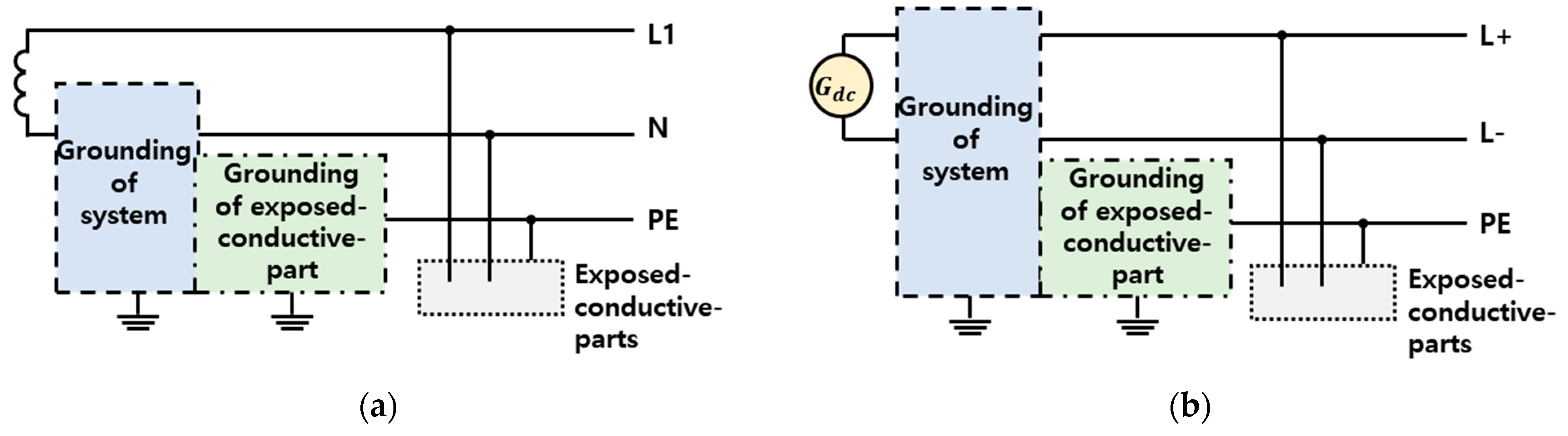
Figure 2 presents a comparison of the conventional grounding system between two-wire AC and DC systems. As described above, both power systems can be classified based on whether the grounding of the system and grounding of the exposed conductive parts are connected directly with the wires or not. In a two-wire system, the AC system can be classified based on the wires and phases; however, the connecting point with the ground is conventionally decided at the neutral line (N). Meanwhile, because the connecting point is not decided in a DC system, the grounding of the system can be connected with either a positive line (L+), negative line (L−), or an artificial point. Therefore, the two-wire DC system has various classifications based on the grounding configurations.
In addition to the IEC standard, the mid-point grounding DC system, which is one of the two-wire DC power systems, was investigated in this study owing to the following reasons.
First, in South Korea, the voltage between the line and ground is limited to less than 300 V in low-voltage households to ensure the safety of the end user. Although it has not been standardized, the global voltage rating at the end user is recognized as 380 V. Therefore, the voltage needs to be divided in half using the mid-point ground system.
Second, the mid-point ground system is advantageous when developing the protection in a two-wire DC system. Unlike AC systems, there are numerous blind spots in the protection of DC systems because of the polarity. In the isolated system (IT), it is difficult to detect the fault because there is no return path when the first fault occurs, as illustrated in Figure 3a. Here, the blue and red arrows indicate that the fault current path and fault, respectively. Although there are methods that use insulation monitoring, the device is unsuitable for ensuring the safety of the end user because fault detection is time-consuming. Moreover, there are blind spots in fault protection in a grounded system with positive or negative lines, such as TT and TN systems. For instance, the positive grounded TT system cannot detect the first positive ground fault, as depicted in Figure 3b.

2.2. Human Effect of the Current Flow

Figure 4 illustrates the statistics of electrical accidents in South Korea over the last decade [27]. In 2011, the number of fatalities and injuries were 49 and 508, respectively, which reduced to 13 and 395 by 2020. Despite the reduced number of casualties, accidents continue to occur more frequently, with over 400 people electrocuted each year over the last decade. Therefore, it is imperative to consider human electric shock characteristics to develop safer LVDC systems.
The IEC 60479 standard is based on the effect of current on human beings and specifies the relationship between the magnitude of current passing through the body and the duration of the current flow. In IEC 60479, the characteristics are based on whether the current flow is DC or AC.
In human beings, ventricular fibrillation (VF) is a dangerous condition that can occur during electrocution. The threshold of VF is different in AC and DC current flow. Generally, DC current flow has a smaller effect on the human body than an AC current flow. As a result, most existing studies have considered the effect of AC current flow. Therefore, in this study, the influence between DC current flow in the human body and the ground system is investigated to ensure the safety of household LVDC systems.

2.2.1. Effects of DC Current Flow on Humans

In IEC 60479-1, the relationship between the magnitude of the body current and duration of current flow is described, as illustrated in Figure 5, and the physiological effects are classified into four categories—DC-1–4. Figure 5 depicts the flowing path from the feet to the left hand. The physiological effects of each category are listed in Table 1. In DC current flow, the direction of the current flow is crucial because the values that correspond to the longitudinal downward current path have doubled thresholds for VF values compared to the values for the upward current path. In DC current flow, the threshold is approximately half the threshold of AC current flow. In other words, DC current flow tends to be relatively safer.
The graph in Figure 5 illustrates the current effects on the body when the duration time varies from 10 ms to 10,000 ms; however, it does not consider durations under 10 ms. Thus, another element should be analyzed to consider short current flow in the body, such as capacitor discharges or impulses.

2.2.2. Effects of Impulse Current on Humans

IEC 60479-2 specifies the effects of electrical shocks on human beings caused by capacitor discharge (impulsive current), which has characteristics when the duration of current flow is less than 10 ms. Short-duration impulse currents have different characteristics compared to a current flow of more than 10 ms.
The current with the peak value ( I C P ) and time constant T has a similar effect to the equivalent DC current having a value I C _ R M S and duration 3T. More specifically, I C _ R M S is obtained by dividing the value of I C P by root 6. The summarized equivalent current is displayed in Figure 6a and Equation (1).
I C _ R M S = I C P × 1 6 .
According to IEC 60479-2, Figure 6b depicts the probability of fibrillation risk for current flowing in the path from the left hand to the feet, relative to the body current magnitude and duration of the short current. The physiological effects of each zone are listed in Table 2. Generally, as depicted in Figure 6b, an equivalent body current of less than approximately 700 mA does not influence the physiological effects (VF), regardless of the duration of the impulsive current. Therefore, the impulse current can be ignored if the ground system was designed to include the duration of current and body current.

3. Background Knowledge of the Parameters

As mentioned previously, the advantages of the mid-point ground system can overcome the limitations of the other ground system in mono-polar power systems. Owing to the absence of stereotyped configurations, the mid-point ground system can be configured in different ways, as shown in Figure 7.

3.1. Mid-Point Ground Using the Resistances

A mid-point ground system can use resistors. Accordingly, two resistors are connected in series, and the mid-point of the high resistances is grounded to Earth, as illustrated in Figure 7a. Since high resistances were used to create the artificial neutral point, it can reduce the voltage between the line and Earth to ensure safety. Moreover, the configuration reduces the fault current scale by the equivalent resistance and detects whether the fault occurs in the positive line or negative line. However, this resistance ground system has a small current flowing through the resistors, generating power loss (heat) in a normal state. Consequently, the efficiency, which is the biggest advantage of an LVDC system, deteriorates. Several studies have proposed the use of devices, such as diodes and thyristors, to solve the power loss problem. Capacitors are used in this study to propose the design method to ensure electrical safety.

3.2. Mid-Point Ground Using Capacitors

A capacitor that stores electrical energy in an electric field is considered to be in OPEN state in a steady DC system. Hence, they have high impedances unless there is a voltage variation, such as system start or fault occurrence. In this study, the mid-point ground system was composed using these characteristics, and a fault detection method is proposed using the capacitor discharge.

3.2.1. Configuration of Mid-Point Ground Using the Capacitor

Using the capacitors as the mid-point grounding system in a two-wire DC system blocks the current and reduces power loss in normal operation. Figure 7b presents a representative configuration of the mid-point ground system using two capacitors. The two capacitors are connected in series, and the mid-point of the capacitors are grounded to the Earth. The configuration is relatively simple and effectively reduces the voltage between the line and Earth, similar to the mid-point grounding system that uses resistors. However, the system using capacitors is vulnerable to high-frequency noise and possesses different characteristics in current flow owing to the capacitor discharge when a fault occurs.
In particular, since the capacitor discharge current is extremely high with an impulsive waveform, the characteristics should be considered when designing the mid-point grounding system using capacitors. Moreover, technical details, such as protection devices (e.g., sensing and tripping), should be considered because the industry related to DC electrical devices is still developing.

3.2.2. Characteristics of the Capacitor Discharge

The equation of the capacitor discharge current and the peak current is expressed in Equations (2) and (3) from IEC 61660-1.
i c t = I p c   e t τ ,
I p c = k c E c R C B r ,
where I p c , τ ,   k c ,   E c , ,   and R C B r denote the peak value of the initial discharge current, time constant, coefficient, capacitor voltage before the fault, and equivalent resistance, respectively.
The peak value of the initial discharge current is changed by the capacitor voltage and equivalent resistance. The equivalent resistance, including the capacitor internal line, fault resistance, is generally low when the ground fault occurs; as a result, the peak current can reach hundreds of amperes. The resulting current, combined with the load current, can damage equipment and pose a risk of electrocution. The equivalent resistance is increased by using the series-connected resistors with a capacitor, and the high fault current can reduce the capacitor discharging current during a fault.
The duration of the discharge current is concerned with the time constant ( τ ), which is a product of resistance and capacitance in an RC circuit. This study proposes the parameters for the resistors and capacitors for a mid-point ground system composed of resistors and capacitors.

3.3. Parameter Design of Mid-Point Ground Using Capacitors

As expressed in Equations (2) and (3), the capacitor discharge current depends on the equivalent resistance, capacitance, and capacitor voltage. The capacitor voltage before the fault occurred cannot be controlled because it is determined by the system voltage. Therefore, the resistance and capacitance should be selected to ensure the safety of users from electrical accidents. Moreover, the selection should be compatible with the technical level of protective devices operated by a leakage current.

3.3.1. Resistance

First, the current flowing from the feet to the left hand should be limited under zone DC-4, shown in Figure 5, or zone C1, shown in Figure 6b, which can cause VF. The minimum threshold current of VF, regardless of the duration of the current time, is approximately 120 mA in both graphs. Therefore, the current flowing from the feet to the left hand is maintained under 100 mA with a safety margin. The RMS value of the 100-mA current has a similar effect on a human being as a capacitor discharge current with a 100 × 6 mA peak value, as specified in Equation (1).
However, this current is based on the feet to the left hand. Thus, the current flowing in a different pathway needs to change to the current flowing from the feet to the left-hand pathway, and the transformation is expressed in Equation (4).
I h = I r e f F ,
where I h ,   I r e f ,     and   F denote the current passing the body for the paths listed in Table 3, the current for the path from the feet to the left hand, and the application of the heart-current factor, respectively. The heart-current factors are applied based on the currents listed in Table 3.
For instance, a flow of 1 A of current in the path from the left hand to the right, with a heart-current factor of 0.4, has the same VF risk when a current of 0.4 A flows in the path from the feet to the left hand.
Accordingly, the resistance should satisfy that the body current flowing from the feet to the left hand is less than 100 × 6 mA for all current paths listed in Table 3.

3.3.2. Capacitance

The residual current detector (RCD) requires the current and time over the threshold for operation. The capacitor in the mid-point grounding system maintains the discharge current to enable the DC RCD to detect a fault current.
Generally, in the Korea Electro-technical code (KEC) of South Korea, AC RCDs with an operational trip current of 30 mA and trip time of 30 ms have been used to prevent leakage currents in the household to ensure consumer safety. However, there are no existing standards or guidelines for the product specifications and operation of DC RCDs. IEC 62423 specifies that B-type RCDs can be applied to cases that contain DC pulses; however, it does not mean that it can be used in DC systems. As a result, it is difficult to use B-type RCDs considering the operating time and sensitivity of the DC RCD in the standard. Considering that there are no commercial products of DC RCD for residual current protection, this study selected the parameters of the capacitor by reflecting the performance of the DC RCD, which is currently under development.
Considering the technology maturity and development status of the DC technical, it is necessary to adjust the AC performance specs instead of using the original settings. A protective device company, DACO, manufactures DC RCDs with an operational trip current of 12 mA and trip time of 80 ms. Figure 8 illustrates the leakage current waveform of the DC RCD trip test that occurred at an artificial leakage current of 14 mA. In the test, the DC RCD operated and cleared the fault within 80 ms.
With references based on KEC and technology maturity to this margin, this study adopted the minimum specification of the RCD at an operational trip current of 30 mA and trip time of 100 ms. To satisfy this condition, the current at 100 ms after the occurrence of a fault should not be less than 30 mA.
The capacitance for the mid-point ground system can be obtained from Equation (5), which is derived from Equation (2).
C = t R C B r × ln I P C ln i c t

4. Simulation and Results

4.1. Simulation Modeling

In this study, a simulation was performed following the model to examine the fault characteristics and risk of human electric shock when using the mid-point grounding system with resistors and capacitors. Accordingly, six cases of simulations, as listed in Table 4, were performed to examine the operational characteristics of the DC RCD via the capacitor discharge and fault current limit characteristics of the mid-point grounding system with resistors and capacitors.

4.1.1. LVDC Household Simulation Circuit

For the simulations in MATLAB/Simulink, the LVDC system was configured as shown in Figure 9. The simulation circuit simulated a mono-polar IT system with a mid-point ground. The configuration was simplified using a DC power source, DC/DC converter, mid-point ground, and load. The mid-point ground was simulated using the configurations presented in Figure 7, and an isolation DC/DC converter was used to ensure that there would be no effect of fault between the primary and secondary sides. Table 5 lists the detailed specifications. A permanent fault was simulated at 30 ms on the positive line, with a fault impedance of 10 Ω.
In Figure 9, i and v represent the current and voltage flowing in the line. The subscripts mid, 1, 2, and F denote the mid-point, front of the mid-point, back of the mid-point, and fault point, respectively. The superscripts P, N, and G denote the positive line, negative line, and Earth-connected line, respectively.

4.1.2. Body Impedance Parameters

Depending on the standard, the human body impedance varies to a certain extent. However, the body impedance specified in IEC 60479-1 was applied in this study. This standard explains that the internal impendence of the human body is approximately 500 Ω and specifies that, when considering the contact resistance, the body resistance at a contact voltage of 400 V is approximately 700 Ω; these values were applied as reference values. Here, the human resistance of 700 Ω represents the body resistance in the hand-to-hand path.
In contrast, IEC 60479-1 specifies the current path-based body resistance ratio based on the hand-to-foot path. Table 6 indicates the impedance ratio for each current path based on the hand-to-foot path and the ratio of converting it into the case of using the hand-to-hand path. Additionally, Table 6 indicates the body impedance variation depending on the path of the body current. The specifications mention a minimum of 285.38 Ω in the case of the seat-to-both-hands path and a maximum of 880.42 Ω in the case of the left-foot-to-right-foot path.
Along with the impedance change for the body current path, the heart-current factor for the aforementioned paths should be considered to more accurately confirm the impact of electric shocks on humans according to electric shock paths.

4.2. Simulation Results

MATLAB/Simulink was used to analyze the characteristics of the fault current for the mid-point ground with resistors and capacitors in a mono-polar LVDC system. Through simulations, the fault current path and impact of the resistors and capacitors values were confirmed. Moreover, the DC RCD operation was confirmed according to the design parameters of the mid-point ground.

4.2.1. Fault Current Path

Figure 10 illustrates the current flowing in a household LVDC system in the simulation using Case 3.
Figure 10a presents the current flowing through the mid-point ground system. During a fault, the current ( i m i d G ) flowing from the fault point with a peak of 3.11 A flowed through to the ground; this current was divided into the positive ( i m i d P ) and positive ( i m i d N ) lines, with 1.55 A flowing in each line. These currents represent the discharge currents generated at the capacitors of the positive and negative lines and flowed from the ground in the direction of the line.
Figure 10b presents the line currents in the front of the mid-point ground system ( i 1 P ,   i 1 N ). A current of 1 A flowed before the fault, and a current with a peak value of 2.55 A flowed following the fault. Both lines were in the same direction as the existing current, with an additional current of 1.55 A generated. The additional current represents a discharge current generated by the capacitor discharge of the mid-point ground system in the negative line.
Figure 10c presents the line currents in the back of the mid-point ground system ( i 2 P ,   i 2 N ). In a normal state, the current on the positive line is 1 A; when a fault occurs, the current is temporarily increased to 4.11 A. It was confirmed that a current of 3.11 A flowing at the fault point was added by circulating the ground and mid-point. The additional current generated from the capacitor discharge currents of the positive and negative lines at the mid-point ground is included. In the case of the negative line, the same current of 1 A flowed regardless of the fault. Accordingly, it is confirmed that the negative line in the back of the mid-point ground is not a path of the capacitor discharge current. Figure 11 shows the fault current paths of the LVDC system using the mid-point ground with resistors and capacitors during a positive fault occurred.

4.2.2. Fault Current according to Values of Resistors and Capacitors

Figure 12 presents the current flowing from the fault point to the mid-point ground ( i m i d G ) for each case. Figure 12a displays a peak value of 3.11 A for a resistance of 100 Ω in the mid-point ground system. In Case 1, there was no attenuation after the fault because only resistors were used. However, attenuation occurred in Cases 2 and 3, where capacitors were used. The time constants considering only the mid-point were 0.3 ms and 3 ms, respectively, and the simulation-based time constants were 0.36 ms and 3.63 ms, respectively, which were similar to the above values. A slight error in the time constant occurred owing to the lines, fault resistance, and Earth resistance.
Figure 12b displays a peak value of 0.372 A for a resistance of 1000 Ω in the mid-point ground system. In Case 4, attenuation did not occur after the fault occurred because only resistors were used. However, attenuation occurred in Cases 5 and 6, where capacitors were used. The time constants considering only the mid-point were 3 ms and 30 ms, respectively, and the simulation-based time constants were 3.04 ms and 30.25 ms, respectively, which are comparable with the above values.
It is demonstrated that there is a difference in the magnitude in the order of ten between the resistance of the mid-point ground used in Figure 12a and that used in Figure 12b. However, the difference in the fault current is not as high as ten times, primarily because the voltage at the fault point is different owing to the fault resistance. Figure 13 illustrates the voltage at the fault point when a fault occurred, where it is shown that the time constant characteristics are comparable to those of the fault current. In the case of using a mid-point ground system of 100 Ω, the peak voltage at the fault point ( v F ) is 31.07 V. In the case of using a mid-point ground system of 1000 Ω, the peak voltage at the fault point ( v F ) is 3.73 V. Their difference is not in the order of ten because the voltage of fault resistance and voltage of resistance in the mid-point ground system are distributed when a fault occurs. Therefore, a higher voltage is allocated to the capacitors in the mid-point ground system in the case of using 1000 Ω than in the case of using 100 Ω. The voltage at the fault point varies, as shown above, and the difference in the peak value of the fault current between Figure 12a,b is not ten times.
Figure 14 shows the current flowing through the resistor in the positive line ( i m i d P ) and the current flowing across the resistor in the negative line ( i m i d N ) in the mid-point ground system when a failure occurs for each case. Figure 14a shows the case of using 100 Ω as the mid-point resistance. In Case 1, a current of 1.9 A flowed before the fault occurred, following which it immediately increased to 3.46 A. In contrast, in Cases 2 and 3, no current flowed through the capacitor before the fault occurred. However, following the fault, discharge currents with time constants of 0.36 ms and 3.63 ms and a peak value of 1.557 A were generated on the positive and negative lines, respectively.
Figure 14b presents the case of using 1000 Ω as the mid-point resistance. In Case 4, a current of 0.19 A flowed before the fault occurred, which immediately increased to 0.376 A after the fault. In contrast, in Cases 5 and 6, no current flowed in the capacitor before the fault occurred. However, following the fault, discharge currents with time constants of 3.045 ms and 60.249 ms and a peak value of 0.186 A were generated in the positive and negative lines, respectively. As for the currents flowing in both the positive and negative lines in Figure 14, it is confirmed that the current flowing upwards from Earth in Figure 13 is split equally into halves on both sides, with the same time constants.

4.2.3. Selection of Resistance and Capacitance Parameters

To derive the parameters of the mid-point ground system using capacitors and resistors by considering the human effects, the resistances and capacitances of the mid-point ground system were calculated for a reference value of 700 Ω based on the hand-to-hand electric shock current path, as specified earlier.
Table 7 lists the resistance values calculated to make the equivalent current flowing to the heart less than 100 mA, which prevents VF, for each current flow path and the capacitance value for detecting the discharge current of the DC RCD.
I h _ R M S , I h _ P , I P , and R b o d y denote the RMS value of the current flowing to the heart according to Equation (1), peak value of the safe current flowing to the heart after the generation of the discharge current, body current for each path reflecting F, and the body impedance of the current path, respectively.
The resistance value of the mid-point ground system (Rm) was calculated to ensure a safe current flows to the heart, i.e., less than 100 mA, considering R b o d y at a system voltage of 380 V. Here, the 1872.49 Ω of the Current Path (10), which has the largest Rm value, was selected as the minimum requirement to ensure the safety of VF against electrical shock of all pathways.
Furthermore, the capacitor value for each path was calculated using Equation (5) to detect the discharge current, ensuring that the current value at 0.1 s after a fault is greater than or equal to 30 mA. Here, Current Path (7) was chosen as the minimum requirement because it had the largest capacitance of 65.04 µF.
In Table 8, the current RMS value flowing to the heart and the discharging current value at 0.1 s following a fault are listed for the case when applying the largest capacitance or resistance values among the values derived from Table 7 to different paths. The red highlight in Table 8 indicates that the values do not satisfy the conditions, which are the current RMS value flowing to the heart or the value at 0.1 s after the occurrence of the fault.
When the values of Rm = 48.18 Ω and C = 65.04 µF derived from Current Path (7) were applied, three paths satisfy both the current RMS value flowing to the heart and the value at 0.1 s after the fault. However, highlighted nine cases do not satisfy the condition of the current RMS value flowing to the heart, and one path does not satisfy both conditions.
When the values of Rm = 1872.49 Ω and C = 25.36 µF derived from Current Path (10) are applied, nine paths are obtained that satisfy both the current RMS value flowing to the heart and the value at 0.1 s following the fault. All cases satisfy the current RMS condition of the current flowing to the heart, whereas four paths do not satisfy both conditions.
When Rm = 1872.49 Ω and C = 65.04 µF are applied to satisfy the minimum requirement of the resistance and the current detection condition, it was found that both conditions are satisfied for all paths. However, for all paths, the current value at 0.1 s following the fault was more than twice as large as the 30-mA-current required for the operation and detection of DC RCD. Since a safer system can be possible if this fault current is lowered, a 27.90 µF capacitance was applied with a safety margin of 10% to the capacitor value of Path (10) that derived the minimum resistance requirement. In this case, both conditions were satisfied on all paths, and the fault value decreased at 0.1 s following the occurrence of the fault.

4.2.4. Simulation Verification

Simulations considering a ground fault of 10 Ω fault resistance and human electric shock were performed to verify the designed parameters for the DC RCD operation. Figure 15 shows the fault current in the event of a fault with a fault resistance of 10 Ω and human electric shock when a DC RCD with an operation sensitivity of 30 mA and a fault clearing time of 60 ms was installed. In the case of human electric shock, Path 12, with the smallest human resistance of 285 Ω, and Path 13, with the largest human resistance of 882 Ω, were assumed, and the fault current had the same value as the current flowing through the human body.
When a fault with a fault resistance of 10 Ω occurred, the peak value was 198 mA, and the current value at 60 ms after the fault occurred was 65 mA; it was confirmed that the DC RCD operates normally.
Peak values of 154 mA and 104 mA were generated when electrical shocks occurred involving 285 Ω and 880 Ω loads. Therefore, if the heart-current factor is applied, the RMS currents flowing through the heart are 44.01 mA and 1.70 mA. Accordingly, it was confirmed that the probability of having VF was reduced when the human body received an electric shock. Moreover, the current value at 60 ms after the fault occurred is 58 mA, confirming the normal operation of the DC RCD.

5. Conclusions

Most existing studies on LVDC systems focus on the efficiency and stability of the equipment and power system. Some studies have analyzed the safety of human beings associated with the grounding system. However, the characteristic between grounding and operation of DC RCD used in a household LVDC system was not considered. Therefore, this paper proposes a new grounding system considering the DC RCD to promote human safety.
In this study, the mid-point ground with resistors and capacitors for a mono-polar household LVDC system was investigated to enhance the efficiency and electrical safety of the LVDC system. By investigating the physiological effects for a DC current based on IEC 60479, a configuration of the mid-point ground system, with capacitors and resistors serially set up, was proposed to reduce the ground potential and prevent the loss of the normal state. Moreover, the discharge characteristics of the proposed ground system and the path of the fault current in the event of a fault were analyzed. Moreover, the minimum design requirements of the mid-point ground with resistors and capacitors were suggested by considering the human body impedance that reflects the paths of electrical shock and the technical level of DC RCD, such as the detection and clearing times of the DC RCD. Fault simulations were performed through MATLAB/Simulink to verify these parameters and requirements. Consequently, it was confirmed that the electrical shock risk of the fault discharge current could be reduced, and the DC RCD operates normally. Based on the results of this study, it will be possible to enhance the electrical safety of household LVDC systems in terms of grounding to minimize human electrical shocks.
In the future, analysis and verification tests will be conducted to establish the protective cooperation technique between protective devices based on the grounding system considering the distributed capacitance in the DC system.

Author Contributions

Writing—original draft preparation, S.-T.L.; Supervision, S.-H.L.; Project administration, K.-Y.L.; Review and editing, D.-J.C. All authors have read and agreed to the published version of the manuscript.

Funding

This research was funded by the Energy Efficiency and Resources of the Korea Institute of Energy Technology Evaluation and Planning (KETEP) grant funded by the Korea Government Ministry of Trade, Industry, and Energy (No. 20193810100010).

Institutional Review Board Statement

Not applicable.

Informed Consent Statement

Not applicable.

Data Availability Statement

Not applicable.

Conflicts of Interest

The authors declare no conflict of interest.

References

  1. Wu, Y.K.; Li, Y.H.; Wu, Y.Z. Overview of power system flexibility in a high penetration of renewable energy system. In Proceedings of the 2018 IEEE International Conference on Applied System Invention (ICASI), Chiba, Japan, 13–17 April 2018. [Google Scholar]
  2. Francois, B.; Martino, S.; Tofte, L.S.; Hingray, B.; Mo, B.; Creutin, J.D. Effects of Increased Wind Power Generation on Mid-Norway’s Energy Balance under Climate Change: A Market Based Approach. Energies 2017, 10, 227. [Google Scholar] [CrossRef] [Green Version]
  3. Bharathi, G.J.; Padmanabhan, T.S. Planning and Optimization of Energy Scheduling in Cohesive Renewable Energy Microgrid to Meet Electric Load Demand of an Educational Institution. J. Electr. Eng. Technol. 2022, 17, 3207–3221. [Google Scholar]
  4. Kim, Y. Modeling and Analysis of a DC Electrical System and Controllers for Implementation of a Grid-Interactive Building. Energies 2017, 10, 427. [Google Scholar] [CrossRef] [Green Version]
  5. Aemro, Y.B.; Moura, P.; Almeida, A.T. Design and Modeling of a Standalone DC-Microgrid for Off-Grid Schools in Rural Areas of Developing Countries. Energies 2020, 13, 6379. [Google Scholar] [CrossRef]
  6. Li, L.; Li, K.J.; Sun, K.; Liu, Z.; Lee, W.J. A Comparative Study on Voltage Level Standard for DC Residential Power Systems. IEEE Trans. Ind. Appl. 2022, 58, 1446–1455. [Google Scholar] [CrossRef]
  7. Azaioud, H.; Claeys, R.; Knockaert, J.; Vandevelde, L.; Desmet, J. A Low-Voltage DC Backbone with Aggregated RES and BESS: Benefits Compared to a Traditional Low-Voltage AC System. Energies 2021, 14, 1420. [Google Scholar] [CrossRef]
  8. Gelani, H.E.; Dastgeer, F.; Nasir, M.; Khan, S.; Guerrero, J.M. AC vs. DC Distribution Efficiency: Are We on the Right Path? Energies 2021, 14, 4039. [Google Scholar] [CrossRef]
  9. Seo, H.C.; Gwon, G.H.; Park, K.W. New Protection Method Considering Fault Section in LVDC Distribution System with PV System. J. Electr. Eng. Technol. 2022, 29, pp. 1–10. Available online: https://link.springer.com/article/10.1007/s42835-022-01224-x (accessed on 4 November 2022).
  10. Chauhan, R.K.; Chauhan, K.; Subrahmanyam, B.R.; Singh, A.G.; Garg, M.M. Distributed and centralized autonomous DC microgrid for residential buildings: A case study. J. Build. Eng. 2020, 27, 100978. [Google Scholar] [CrossRef]
  11. Kitson, J.; Williamson, S.J.; Harper, P.W.; McMahon, C.A.; Rosenberg, G.; Tierney, M.J.; Bell, K.; Gautam, B. Modeling of an expandable, reconfigurable, renewable DC microgrid for off-grid communities. Energy 2018, 160, 142–153. [Google Scholar] [CrossRef] [Green Version]
  12. Yoon, K.-H.; Shin, J.-W.; Kim, J.-C.; Lee, H.-J.; Kim, J.-S. Simulation of a Low-Voltage Direct Current System Using T-SFCL to Enhance Low Voltage Ride through Capability. Energies 2022, 15, 2111. [Google Scholar] [CrossRef]
  13. Liao, J.; Guo, C.; Zeng, L.; Kang, W.; Zhou, N.; Wang, Q. Analysis of Residual Current in Low-Voltage Bipolar DC System and Improved Residual Current Protection Scheme. IEEE Trans. Instrum. Meas. 2022, 71, 1–12. [Google Scholar] [CrossRef]
  14. Verma, P.; Katal, N.; Sharma, B.; Chowdhury, S.; Mehbodniya, A.; Webber, J.L.; Bostani, A. Voltage Rise Mitigation in PV Rich LV Distribution Networks Using DC/DC Converter Level Active Power Curtailment Method. Energies 2022, 15, 5901. [Google Scholar] [CrossRef]
  15. Hamed, S.B.; Hamed, M.B.; Sbita, L. Robust Voltage Control of a Buck DC-DC Converter: A Sliding Mode Approach. Energies 2022, 15, 6128. [Google Scholar] [CrossRef]
  16. Chiumeo, R.; Raggini, D.; Veroni, A.; Clerici, A. Comparative Analysis of PI and ADRC Control through CHIL Real Time Simulations of a DC-DC DAB into a Multi-Terminal MVDC/LVDC Distribution Network. Energies 2022, 15, 7631. [Google Scholar] [CrossRef]
  17. Alluhaidan, M.; Almutairy, I. Modeling and Protection for Low-Voltage DC Microgrids Riding Through Short Circuiting. Procedia Comput. Sci. 2017, 114, 457–464. [Google Scholar] [CrossRef]
  18. Emhemed, A.A.S.; Fong, K.; Fletcher, S.; Burt, G.M. Validation of Fast and Selective Protection Scheme for an LVDC Distribution Network. IEEE Trans. Power Deliv. 2017, 32, 1432–1440. [Google Scholar] [CrossRef] [Green Version]
  19. Sharama, N.K.; Saxena, A.; Samantaray, S.R. An Intelligent Differential Protection Scheme for DC Microgrid. In Proceedings of the IEEE International Conference on Power Systems (ICPS), Kharagpur, India, 16–18 December 2021; pp. 1–6. [Google Scholar]
  20. Mishra, M.; Patnaik, B.; Biswal, M.; Hasan, S.; Bansa, R. A systematic review on DC-microgrid protection and grounding techniques: Issues, challenges and future perspective. Appl. Energy 2022, 313, 118810. [Google Scholar] [CrossRef]
  21. Oliverira, T.R.; Bolzon, A.S.; Donoso-Garcia, P.F. Grounding and safety considerations for residential DC microgrids. In Proceedings of the IECON 2014—40th Annual Conference of the IEEE Industrial Electronics Society, Dallas, TX, USA, 26 February 2015; pp. 5526–5532. [Google Scholar]
  22. Li, L.; Yong, J.; Zeng, L.; Wang, X. Investigation on the System Grounding Types for Low Voltage Direct Current Systems. In Proceedings of the 2013 IEEE Electrical Power & Energy Conference, Halifax, NS, Canada, 1–23 August 2013; pp. 1–5. [Google Scholar]
  23. Lim, S.T.; Lee, K.Y.; Kim, D.W.; Chae, D.J.; Lim, D.S.; Moon, J.H. Selection of the Earthing Impedance at the Source and Electrical Human Effect in IT Ground LVDC System for the End User’s. Trans. Korean Inst. Electr. Eng. 2021, 70, 432–438. [Google Scholar] [CrossRef]
  24. Mohammadi, J.; Ajaei, F.B.; Stevens, G. Grounding the DC Microgrid. IEEE Trans. Ind. Appl. 2019, 55, 4490–4499. [Google Scholar] [CrossRef]
  25. Seo, H.C.; Gwon, G.H.; Park, G.W. Fault Section Estimation in Radial LVDC Distribution System Using Wavelet Transform. Energies 2021, 14, 8486. [Google Scholar] [CrossRef]
  26. Lee, K.M.; Kim, J.W.; Park, C.W. Detection Method of Pole to Ground Fault in Ungrounded LVDC Distribution Grid Using DWT. J. Electr. Eng. Technol. 2019, 14, 1529–1536. [Google Scholar] [CrossRef]
  27. Korea Electrical Safety Corporation. A Statistical Analysis on the Electrical Accident. Available online: https://www.kes.go.kr/web/lay1/bbs/S1T110C291/F/101/list.do (accessed on 4 November 2022).
  28. IEC 60479-1; Effects of current on human beings and livestock –Part 1: General aspects. International Electrotechnical Committee: Geneva, Switzerland, 2018.
  29. IEC TS 60479-2; Effects of Current on Human Beings and Livestock–Part 2: Special Aspects. British Standards Institution: Geneva, Switzerland, 2017.
Figure 1. Examples of AC and DC power system classifications based on the phases and wires.
Energies 15 08653 g001
Figure 2. Comparison of the system configurations between AC and DC based on the grounding of the system and exposed conductive part: (a) AC system; (b) DC system.
Energies 15 08653 g002
Figure 3. Example of the protection blind spot in a two-wire DC system under a ground fault: (a) IT system; (b) Positive grounded TT system.
Energies 15 08653 g003
Figure 4. Statistics of electrical accidents over the last decade in South Korea (2011–2020).
Energies 15 08653 g004
Figure 5. Graph illustrating the time/current zones of effects of DC current flow on the human body for a longitudinal upward current path (feet to left hand).
Energies 15 08653 g005
Figure 6. Impulse current characteristics caused by capacitor discharge: (a) Equivalent DC current of impulse current; (b) Probability of fibrillation risk for current flowing in the path from the left hand to feet in IEC 60479-2.
Energies 15 08653 g006
Figure 7. Types of mid-point grounding systems: (a) Mid-point ground system with two resistors; (b) Mid-point ground system with two capacitors; (c) Mid-point ground system with two resistors and capacitors.
Energies 15 08653 g007
Figure 8. Waveform of the operational test that generated an artificial leakage current of 14 mA for the DC RCD under development.
Energies 15 08653 g008
Figure 9. Configuration of the simulation circuit developed in MATLAB/Simulink.
Energies 15 08653 g009
Figure 10. Waveforms of the discharge current of the simulation circuit using the mid-point ground system: (a) Capacitor discharge current in the mid-point ground system; (b) Current in front of the ground system; (c) Current in the back of the ground system.
Energies 15 08653 g010
Figure 11. Fault current path for the mid-point ground system with capacitors.
Energies 15 08653 g011
Figure 12. Fault current for a fault resistance of 10 Ω (a) Resistance used in mid-point ground was 100 Ω; (b) Resistance used in mid-point ground was 1000 Ω.
Energies 15 08653 g012
Figure 13. Voltage of the fault point when a fault resistance of 10 Ω occurred (a) Resistance used in the mid-point ground is 100 Ω; (b) Resistance used in the mid-point ground is 1000 Ω.
Energies 15 08653 g013
Figure 14. Current waveforms flowing through the negative ( i m i d N ) and positive ( i m i d P ) resistors in the mid-point ground system: (a) Case with 100 Ω as the resistance; (b) Case with 1000 Ω as the resistance.
Energies 15 08653 g014
Figure 15. Waveform of the fault current for a ground fault with a 10 Ω impedance and the electrical shock corresponding to current paths 12 and 13.
Energies 15 08653 g015
Table 1. Physiological effects for a DC current flow for more than 10 ms in IEC 60479 [28].
ZonePhysiological Effects
DC-1Slight pricking sensation.
DC-2Involuntary muscular contractions; however, no harmful electrical physiological effects.
DC-3Strong involuntary muscular reactions and reversible disturbances in the formation and conduction of impulses in the heart may occur. However, no organic damage is expected.
DC-4Patho-physiological effects may occur, such as cardiac arrest, breathing arrest, burns, and other cellular damage. Probability of VF is low.
(DC-4.1) Probability of ventricular fibrillation increases up to approximately 5%.
(DC-4.2) Probability of ventricular fibrillation up to approximately 50%.
(DC-4.3) Probability of ventricular fibrillation above 50%.
Table 2. Physiological effects based on the current flow for less than 10 ms in IEC 60479-2 [29].
ZoneRisk of the Fibrillation
C0No fibrillation
C1Low risk of fibrillation (up to 5% probability)
C2Average risk of fibrillation (up to 50% probability)
C3High risk of fibrillation (more than 50% probability)
Table 3. Heart-current factor F for different current paths.
Current PathF
Left hand to left foot, right foot, or to both feet1
Both hands to both feet1
Left hand to right hand0.4
Right hand to left foot, right foot, or to both feet0.8
Back to right hand0.3
Back to left hand0.7
Chest to right hand1.3
Chest to left hand1.5
Seat to left hand, right hand, or to both hands0.7
Left foot to right foot0.04
Table 4. Simulation cases according to the mid-point ground with resistors and capacitors.
CaseMid-Point GroundR (Ω)C (µF)
1R1000
2RC1003
3RC10030
4R10000
5RC10003
6RC100030
Table 5. Simulation parameters.
ComponentValuesUnit
Isolated DC/DC Converter 750/380V
Z L i n e R L i n e 0.164Ω/km
L L i n e 0.26mH/km
Line length0.2km
Load380Ω
R F 10Ω
Table 6. Ratio of the body resistance and body resistance according to the current path.
Current PathBody Resistance Ratio Based on Hand-to-Foot Path (%)Body Resistance Ratio Based on Hand-to-Hand Path (%)Resistance Based on Hand-to-Hand Path (Ω)
(1)Left hand to left foot or right foot100123.92867.41
(2)Left hand to both feet74.2592.01644.05
(3)Both hands to both feet50.6562.76439.34
(4)Left hand to right hand80.7100.00700.00
(5)Right hand to left foot or right foot100123.92867.41
(6)Right hand to both feet74.2592.01644.05
(7)Back to right hand48.159.60417.22
(8)Back to left hand48.159.60417.22
(9)Chest to right hand52.464.93454.52
(10)Chest to left hand52.464.93454.52
(11)Seat to left hand or right hand56.570.01490.09
(12)Seat to both hands32.940.77285.38
(13)Left foot to right foot101.5125.77880.42
Table 7. Parameter calculation reflecting current flow path in human beings (700 Ω) when the mid-point ground using the RC element is applied in a 380 V source system.
Current Path I h _ R M S   ( mA ) I h _ P   ( mA ) I P ( = I h _ P / F )   ( mA ) R b o d y   ( Ω ) Rm (Ω)I (0.1 s) (mA)C (µF)
(1)100244.95244.95867.41683.933030.70
(2)100244.95244.95644.05907.293030.70
(3)100244.95244.95439.341112.003030.70
(4)100244.95612.37700.00−79.463053.43
(5)100244.95306.19867.41373.663034.69
(6)100244.95306.19644.05597.023034.69
(7)100244.95816.50417.2248.183065.04
(8)100244.95349.93417.22668.723037.49
(9)100244.95188.42454.521562.223026.99
(10)100244.95163.30454.521872.493025.36
(11)100244.95349.93490.09595.853037.49
(12)100244.95349.93285.38800.563037.49
(13)100244.956123.72880.42−818.3730302.99
Table 8. Current RMS value flowing to the heart and the discharging current value at 0.1 s after the fault based on the resistance and capacitance derived from Table 7.
Current PathRm = 48.18 Ω, C = 65.04 µFRm = 1872.49 Ω, C = 25.36 µFRm = 1872.49 Ω, C = 65.04 µFRm = 1872.49 Ω, C = 27.90 µF
IhrmsI (0.1)IhrmsI (0.1)IhrmsI (0.1)IhrmsI (0.1)
(1)169.4477.40856.6232.8956.6279.1356.6237.49
(2)224.1159.55561.6531.5161.6581.9761.6536.34
(3)318.2133.27767.1029.8667.1084.5367.1034.87
(4)82.9465.05824.1231.9024.1281.2624.1236.67
(5)135.5577.40845.3032.8945.3079.1345.3037.49
(6)179.2959.55549.3231.5149.3281.9749.3236.34
(7)100.0030.00620.3329.6520.3384.8020.3334.69
(8)233.3330.00647.4329.6547.4384.8047.4334.69
(9)401.1835.49686.6730.0086.6784.3486.6735.00
(10)462.9035.496100.0030.00100.0084.34100.0035.00
(11)201.7540.57545.9630.3145.9683.9045.9635.28
(12)325.5611.34450.3228.3250.3286.3650.3233.45
(13)6.6878.1412.2532.962.2578.972.2537.54
Publisher’s Note: MDPI stays neutral with regard to jurisdictional claims in published maps and institutional affiliations.

