Abstract
Carbonated water has proven advantages over conventional CO2 injection in terms of arresting free CO2 mobility, low-pressure injection, lower volume requirement, and higher efficiency. The term “engineered water” is designated to selective ion-spiked injection water with the advantage of the ion-exchange reactions with the rock minerals and releasing trapped oil. This article investigated the synergic effect of dissolved CO2 and engineered water for oil recovery and understanding inner mechanisms. Recovery efficiencies were evaluated through coreflood studies, which revealed that the hybrid water could recover 6–10% more oil than engineered water and about 3% more than carbonated water. HP-HT pendant-drop studies show the insignificance of IFT reduction. Wettability change from oil wet to near-water wet is attributed as a significant factor. The dissolution of Ca2+ and Mg2+ and deposition of SO42− observed in coreflooding may have a significant contribution to oil recovery. Pore enlargement evidenced in NMR-PSD and NMR-ICP results support this claim. The study confirmed that the EWI-CWI hybrid technique could be a promising EOR method, eliminating the requirement for high-pressure injection, the problems of gravity segregation, and the early breakthrough of CO2. It can also be an effective EOR solution, providing a significant cost advantage and higher oil recovery in addition to the environmental benefits of CO2 sequestration.
1. Introduction
Nearly sixty percent of the world’s oil reserves and recovery come from carbonate reservoirs. However, extraction from carbonate reservoirs is generally more challenging than sandstone reservoirs [1]. Firstly, most of them are naturally fractured, and secondly, more than 20% of current oil production is from naturally fractured reservoirs [2]. Secondly, up to 77% are oil wet [3], rendering them less susceptible to spontaneous water imbibition. Several enhanced oil recovery (EOR) techniques have been developed and implemented to facilitate improved water imbibition, higher oil mobility, lower interfacial tension, and ultimately higher recovery. The most notable developments in the area of EOR are low-salinity and engineered water, in which potential determining ions are modified. Water with dissolved CO2 and nanoparticles is also gaining importance in research [4,5].
Various compositions of low-salinity/engineered waters have been extensively evaluated over the last two decades, with a major focus on carbonate reservoirs. A few successful field trials have also been reported [6,7]. CO2 injection at miscible and immiscible states is a matured and proven EOR technique, having advantages such as higher solubility in oil, thus reducing oil viscosity, swelling oil blobs, and enhancing the viscous force of the displacing fluid [8]. On the other hand, the main mechanism behind low-salinity/engineered water’s success is wettability alteration through multicomponent ion exchange (MIE), [9]. Many authors reported that originally oil-wet or mixed-wet reservoir rocks tend to become water wet through the desorption of electrically polar oil compounds from the rock surface [10,11]. The multivalent ions of injected water are exchanged with cations present on the rock surface, thus altering the surface charge of the rock. Bartels et al. [12] reviewed the literature on low-salinity flooding and pointed out that multiple mechanisms are involved in the additional recovery of oil; however, the physics behind individual mechanisms and their interplay does not explain the phenomena completely. This means investigating only one particular mechanism with one length scale is not sufficient.
Other possible mechanisms mentioned in the literature are IFT reduction, rock dissolution, and electrical double-layer expansion. However, none of them has been universally accepted as the most predominant mechanism so far. Judicious selection and modification of injection brine salinity and the ionic composition are the critical aspects of the beneficial effect on the oil–rock–brine interaction. For example, sulfate-enriched brines reduce the oil-water IFT, while oil droplets coalesce more effectively with brine containing Mg2+ and Ca2+ [13]. Though several fields have successfully applied low-salinity/engineered water flooding with tangible benefits [14,15], not enough data are available in the public domain. However, several simulation models are built based on experimental data, including geochemical reactions and resulting wettability alteration, which was history-matched. The results predicted improved oil displacement by engineered water and the optimum ion concentration necessary [16,17]. A field-scale simulation on engineered water injection (EWI) in three synthetic five-spot reservoir models, including homogeneous, heterogeneous with permeability channeling, and heterogeneous with gravity underride reservoirs, was built. By upscaling history-matched coreflood data, it was found that the homogeneous reservoirs are the best candidate for EWI, and the main reason behind the incremental oil recovery is wettability alteration [18].
It is evident from the literature that most authors believe that sulfate ions can initiate an excellent ionic reaction on the rock surface, dissolving the surface and roughening it since this ion is highly reactive on the calcite surface. The contact angle of the oil droplet on the oil-wet rock surface is favorably changed towards more water wet by engineered water, where sulfate ions are artificially spiked four to six times [12]. However, Mg2+ and Ca2+ ions are also claimed to play a role in improving recovery. The coalescence of the oil-brine interface initiated by Mg2+ and Ca2+ ions is more efficient than SO42− as reported by Ayirala et al. [19]. Injecting engineered water into the rock supposedly changes the crude oil composition by forming water micro-dispersions in the oil, which results in greater sweep efficiency due to oil swelling. However, seawater injection recovery improvement is attributed to a change in IFT, too, which leads to greater surface dilatational elasticity [20,21].
Miscible CO2 injection contributed significantly to oil recovery over the past decades, particularly in heavy oil reservoirs. However, recently, the benefits of injecting CO2 dissolved in water have been found to have merits over injecting supercritical CO2. Due to the highly favorable mass transfer mechanism, oil recovery employing carbonated water injection (CWI) can be more efficient in reducing the oil density and viscosity, oil-swelling factor, and creating higher viscous forces than CO2 alone [22]. Apart from these, a better sweep can be expected in CWI due to less gravity segregation and lesser channeling effect due to increased density and viscosity of injected water with dissolved CO2 [23]. According to Emmanuel et al. [24], water-saturated CO2 injection recovered 5 to 9% more oil than a SWAG (simultaneous water and gas) or pure CO2 injection and sequestered 6 to 20% more CO2 in sandstone core plugs.
For further advancement in this area of EOR, it is anticipated that the synergic effect of CO2 dissolved in engineered water could improve recoverable reserve further compared to engineered water or CO2 injected alone. One can find evidence in this regard in the work of Soleimani et al. [25], who reported about 5% additional recovery when engineered carbonated water is used as a displacement fluid when compared with engineered water or CO2 injected alone.
Envisaging the importance and simplicity of these two EOR methods gives very reasonable justification to study them sequentially and simultaneously to evaluate their potential synergic effects. It is also essential to delve into the underlying mechanisms studying the rock–brine–oil interaction. This technique does not require a vast amount of CO2, and more CO2 can be sequestered in the subsurface at significantly lower pressure [26].
In this research, a series of coreflood studies were performed at reservoir temperature and pressure to investigate the recovery potential of engineered water and carbonated engineered water and their individual potential in recovering residual oil using core plugs and crude oil from a local carbonate reservoir. HT-HP pendant-drop setup determined the interfacial tension and contact angle at reservoir temperature and pressure. Finally, NMR porosity and ICP-MS techniques were used to assess mineral dissolution, pore enlargement, and ion-exchange phenomena, which may impact the overall EOR process.
2. Materials and Methods
2.1. Materials
Brines: Base brines were synthesized according to the composition of the formation brine (Middle East field-X, carbonate formation) and the seawater obtained from the field laboratory. In our earlier work [23], it was established that out of five engineered brines evaluated through various laboratory investigations, four-times sulfate-spiked sea water was the most potent engineered water in terms of recovery efficiency. Because of this, four-times sulfate-spiked seawater was selected as the engineered brine in this study. The brine was prepared by the addition of salts to meet the desired ion level. The ionic compositions of the brines used in this study are given in Table 1.

Table 1.
Properties of the brine (approximate value).
Preparation of carbonated brine: To prepare the CSW (carbonated sea water) and CESW (carbonated engineered sea water), the following steps were undertaken:
- (a)
- Two-thirds of a titanium floating piston cylinder was filled with brine, heated to the required temperature with a heating jacket, and increased pressure to 400 psi with the help of a PD pump once the fluid temperature was stabilized;
- (b)
- Started injecting CO2 using a gas booster into the brine with occasional rocking, maintaining the pressure slightly above the set pressure;
- (c)
- Once the brine was saturated with CO2, the cylinder was rocked for 24 h under set pressure and temperature;
- (d)
- Excess, undissolved CO2 was released from the cylinder through careful pressure depletion in steps, finally bringing the pressure down to 400 psi;
- (e)
- The final volume of CO2 in brine was calculated using the CO2 solubility correlation [27] and the CO2 solubility model [28]. The correlation shows that at the given condition, approximately 6.51 mL of CO2 at standard condition, is dissolved in each ml of water.
Crude oil: A surface crude oil sample was obtained from the Field-X using an HP-cylinder under a nitrogen environment. It was vacuum degassed, centrifuged at 3000 rpm to remove suspended particles, and finally filtered with a 0.3-micron filter before use. The properties of the crude oil sample are given in Table 2. It was assumed that the composition of the crude oil must have changed during the journey from the reservoir to the surface separator; still, a surface sample was used due to the high cost of obtaining a representative bottom-hole sample.
Table 2.
Properties of the crude oil at surface conditions.
Porous media (core plugs): Carbonate cores from Field-X were collected from a deep reservoir to perform the oil recovery experiments. Mineralogy analyses show that the rock comprises 93.6% calcite, 5.2% dolomite, and other minor minerals. The cores were subjected to plugging and cleaning (following the procedure described by Farokhpoor, R. et al. [29] as Cleaning Program-1), petrophysical property measurements, and finally, saturation with synthetic formation brine. Porosity and pore volumes of the core plugs were calculated using the brine density, and absolute permeabilities were measured through brine flooding at three different flow rates. Table 3 presents the properties of the core plugs used for coreflood studies. Two sets of core plugs of good integrity were selected for coreflood studies. The first set, comprising two plugs, was selected based on wide permeability variation. The second set of plugs was cut from the closest vicinity and bore almost identical properties, verified through NMR porosity studies.
Table 3.
Properties of the core plugs used for coreflooding studies.
The core plugs were placed in a core holder, and formation water was injected vertically from the bottom at 0.1 cc/min flow, followed by oil until Swirr (irreducible water saturation) was established. The cores were then subjected to aging at 100 °C temperature for four weeks under a confinement pressure of 2000 psi.
2.2. Methods
NMR porosity studies: Pore size distribution (PSD) of the core plugs were measured through liquid-state 1H NMR relaxation technique using NMR Rock Core Analyzer (Magritek Rock Core Analyzer) before and after coreflood recovery studies. This method is fast, convenient, and non-destructive and provides reliable pore information, including the porosity and pore size distributions. The core plugs were cleaned and fully saturated with the respective reservoir formation brine before the NMR-PSD studies. During each measurement, transverse relaxation (T2) spectra were recorded and analyzed by the built-in program of the apparatus, and the total porosity was plotted. Details of the NMR-PSD measurement method can be found elsewhere [30,31].
Interfacial Tension (IFT) and contact angle measurement: To measure the IFT between various brines and crude oil at HT-HP conditions, Sanchez Technologies pendant-drop IFT analyzer (IFT-10-P) was used (Figure 1). All measurements were conducted at the stabilized state of 400 psi and 100 °C. Oil drops were introduced into the IFT cell through a needle with the help of a precision-metering pump. Several drop shapes were analyzed at different time gaps for one pair of fluids to ensure reliable IFT at CO2 phase equilibrium between brine and oil. Anton-Paar DMA HPM was utilized to measure brine and oil densities, providing an accuracy level of ±0.0005 g/cm3. Details of the measurement process can be found elsewhere [32]. The HT-HP pendant-drop equipment comes with a contact angle measurement device. Contact angle under desired HT-HP conditions can be measured by placing a drop of oil on a piece of polished rock. The rock is immersed horizontally in test brine, and the oil drop is released carefully from the bottom of the rock through a needle. A camera attached to a computer measures and calculates the contact angle. After the camera takes the image, a built-in software determines the contact angle θ. Details can be seen elsewhere [33]. In order to decide the time necessary to reach equilibrium between the oil–brine–rock–CO2 and the wettability, some reference was necessary. Al-Mutairi et al. [34], who conducted a detailed study on the effect of CO2 concentration and exposure time on wettability, reported that upon introduction of CO2 into the high-pressure visual wettability sell, the contact angle reached a plateau in less than or within 44 min. Even when the CO2 concentration is doubled, the time to reach equilibrium did not exceed more than six minutes. Thus, it was decided to maintain 120 min of aging time to reach chemical equilibrium for each sample before final contact angle measurements were taken. In fact, from multiple observations, it was seen that there was no change in contact angle after 64 min irrespective of brine composition; however, 120 min was set as the standard exposure time for all the samples. Since the diameter of the oil drop may also affect the contact angle [35], drop sizes were carefully maintained at close to 0.5 cm. Brine density, IFT, and contact angle data are presented in Table 4.
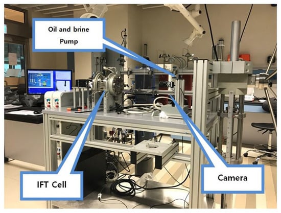
Figure 1.
HP-HT pendant-drop IFT/contact angle set up.
Table 4.
Density of brines and oil-brine IFT at 100 °C and temperature and 500 psi pressure.
- Coreflood Recovery Studies
Coreflooding setup: The HT-HP coreflood setup used for this study is equipped with a high-pressure core holder, two positive displacement (PD) pumps, a back pressure regulator (BPR) fitted with an N2 cylinder, a high-pressure fluid transfer system, an overburden pressure pump, low- and high-range differential pressure transducers, and effluent separator cum collector, confined within a constant-temperature oven.
Coreflooding process: Two sets of coreflood experiments were conducted to compare the effectiveness of different brines. The first set of coreflood used C#33 and C#198, having markedly different petrophysical properties (Table 3), which helped investigate the permeability effect on oil recovery factor. The second set of coreflood used C#41 and C#42 (twin plugs) to ascertain the contribution of sulfate in the CESW. Oil recovery potential in secondary, tertiary, and quaternary flood modes were measured. Flooding continued until Sor for the respective brine was ensured. Stepwise the flood modes were as follows for CF-1 and CF-2:
- Secondary recovery using sea water (this also includes primary recovery in real terms);
- Tertiary recovery using engineered sea water (ESW);
- Quaternary recovery using carbonated engineered brine (CESW);
- Quaternary recovery after 24 h exposure to CESW.
In the second set of corefloods, CF-3 used CSW, and CF-4 used CESW as tertiary recovery fluid.
The following steps were adopted:
We loaded SW, ESW, CSW, and CESW in separate HP cylinders and attained the required temperature. For CSW and ESW, pre-set pressure was maintained with the help of a constant pressure PD pump. We loaded the aged core plug into the core holder and flushed the flow lines with crude oil ensuring complete removal of air and water from the flowlines.
- Next, 500 psi initial confinement pressure was applied and the system stabilized to 100 °C temperature;
- Backpressure was applied and overburden increased in steps to finally achieve 500 psi back pressure and 2000 psi confinement pressure;
- Brine was injected till Sor was reached, followed by oil injection at flow rates ranging from 0.1 cc/min to 0.5 cc/min until Swirr was assured;
- Brine permeability, oil permeability, and oil saturations were measured;
- Secondary recovery potential was measured using seawater;
- The tertiary recovery potential of ESW was measured;
- Quaternary recovery using CESW was measured to find additional recovery potential due to the presence of CO2;
- The new residual oil saturation after each recovery stage was estimated from the total oil produced;
- The displacement efficiency of the flood water was plotted against the pore volume injected in Figure 2, Figure 3, Figure 4 and Figure 5;
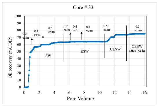 Figure 2. Coreflood with high permeability core plug (K = 20.25 mD). (CF-1 conducted on core plug #33).
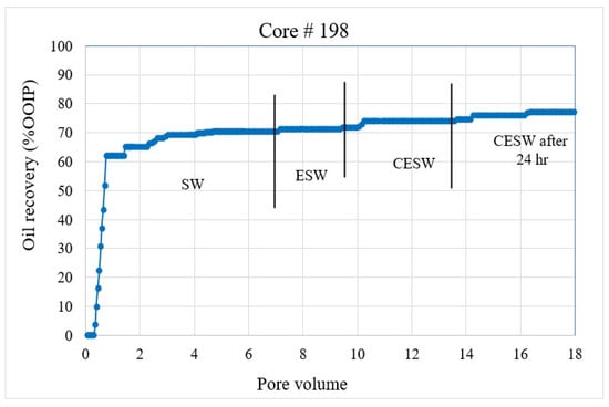 Figure 3. Coreflood with low permeability core plug (K = 1.5 mD). (CF-2 conducted on core plug #198).
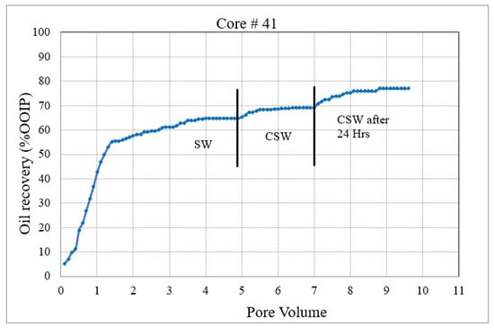 Figure 4. Coreflood with carbonated seawater (CSW). (CF-3 conducted on core plug #41).
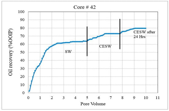 Figure 5. Coreflood with carbonated engineered seawater (CESW). (CF-4 conducted on core plug #42).
 - Permeability plots could not be constructed, as the differential pressure display was erratic, possibly due to the release of dissolved CO2.
Inductively Coupled Plasma Mass Spectrometer (ICP-MS): To identify the possible rock-mineral dissolution by different flood waters, the injected and produced brines during the corefloods were analyzed and compared for ionic composition using Perkin Elmer SCIEX DRC-e ICP-MS. Coreflood effluent samples were collected during each flood mode, and oil was separated from brine using a high-speed centrifuge and filtered using a 0.2-micron filter before ICP-MS analysis. The detailed sample preparation procedure, including acid digestion, can be found in the work of Taiane et al. [36].
3. Results and Discussion
IFT studies: In typical cases, the oil–water IFT varies between 10–30 dynes/cm. However, for effective EOR, the oil–brine IFT needs to be reduced to 10−3 nM/m to achieve a high mobilization of trapped oil [37]. HT-HP IFT studies were conducted using the pendant-drop method to investigate the impact of different brines in this study. Table 4 presents the results of IFT studies between oil and three synthetic brines, including carbonated brines.
The results show that under the condition of temperature and pressure, oil–ESW IFT has reduced slightly compared to oil–SW; however, the difference is negligible and may not contribute much to additional oil recovery. Under the same temperature and pressure conditions, IFT was further reduced by about 40% to 70% when CO2 was dissolved in SW and ESW, respectively, which can be partially attributed to oil swelling and the resulting reduction of oil density and viscosity. The diffusion of CO2 at the interface may also be a reason for the decrease in IFT. Though not significant, this reduction of IFT may contribute to additional oil recovery to some extent. Our observation somewhat agrees with the IFT measured between CO2 and distilled water and NaCl brines under temperature and pressure conditions by Bachu and Bennion [38], who reported a sharp reduction of IFT with CO2 above MMP. In a recent study, Morteza et al. [39] compared IFT of sulfate-spiked carbonated brine with carbonated brine containing CTAB surfactant and observed that values are close. IFT measured by pendant-drop method at HT-HP condition by Yang et al. [40] also showed IFT reduction with increasing temperature, pressure, and CO2 content in the oil. They observed a decrease in IFT from 53.07 mN/m to 34.79 mN/m when CO2 content in the oil was increased from 0 to 65 mol%. Similar results were obtained in percentage terms.
Contact angle: As per the convention, when the rock–oil contact angle is less than 60°, the rock is considered water-wet, and it is oil-wet when the contact angle is greater than 120°. Neutral or intermediate wet rock is supposed to display contact angles ranging from 60–120°. It is well-established that oil recovery is generally higher in intermediate to water-wet rocks than in oil-wet rocks. Wettability is temperature- and pressure-dependent when compressible gas (CO2) is present, and the diffusion is ongoing [41]. Mahani et al. [42] studied the impact of temperature on the wettability of carbonates, and they found that there is no univocal increase in response to seawater and low-salinity brine at elevated temperature; however, dolomite showed greater improvement in wettability. The rock type and mineralogy play a major role in wettability alteration even at elevated temperature. Their study concluded that a combined surface-charge change and double-layer expansion is a plausible mechanism for the wettability alteration in carbonate rocks.
Two hours of aged sample readings were considered assuming the equilibrium was reached [34]. The results presented in Table 4 show that the carbonate rock is oil-wet (124°) when SW is used as the aqueous phase. On spiking the SW with sulfate, the rock wettability is shifted to intermediate wet (93°). Various other authors reported similar observations [23,43]. Though most of these studies were conducted at ambient pressure, it can be safely assumed that with SW and ESW, both being incompressible fluids, pressure has little effect on the contact angle once the CO2 reaches its thermodynamic and chemical equilibria.
CO2 is present in the aqueous system as carbonic acid and bicarbonate ions in the equilibrium state. Part of the CO2 in the aqueous phase diffuses to the oil–rock interface with time. When about 6.5 mL of CO2 is dissolved in SW (i.e., CSW), the contact angle shifted 17° from the original compared to 31° shifting in ESW. Finally, when CESW is used (containing high-sulfate and -bicarbonate ions), the contact angle shifted 44° from the original, converting the rock to near-water wet. Mahani et al. [44] found that contact angle reduction happened due to the low-salinity effect in carbonates, and this is primarily because of surface-charge change even without mineral dissolution. Ruidiaz et al. [45] conducted wettability studies with carbonated water on carbonate cores through spontaneous imbibition. They, too, observed a change of wettability from weakly oil wet to weakly water wet. Seyyedi and Sohrabi [46] reported a higher water imbibition rate and oil recovery when CO2 was dissolved in water. They attributed this mainly to the alteration of wettability towards water wet (in addition to oil swelling, reduction of oil viscosity, reduction of IFT, and mineral dissolution). Studies conducted under similar conditions by Vadhan and Phukan [47] are also noteworthy here. They reported a 36° reduction of contact angle from the original when the brine phase was changed to carbonated smart water. The kinetics of contact angle change are time-constant, and it takes longer than commonly assumed, and there is an electrokinetic ion transport between oil and rock, changing the surface charge [48,49,50].
Coreflood results: CF-1 and CF-2, the first set of coreflood experiments, were conducted to investigate the efficiency of ESW and ESW on oil-wet carbonate rocks in tertiary and quaternary flood modes and with 24 h of exposure to CESW. Figure 2 and Figure 3 present the displacement efficiency of flood water versus pore volume injected (PVi) into the core plugs with permeability values of 20.25 mD and 1.5 mD, respectively. The vertical bars indicate the boundary between different brine floods. This set of experiments was designed to study the effect of permeability on oil recovery and brine properties. Identical flood parameters were applied in secondary, tertiary, and quaternary flood modes. Secondary and tertiary floods were conducted at increasing flow rates from 0.1 cc/min to 0.5 cc/min, as shown in Figure 2. The flow rate was increased when no further oil was produced for at least one pore volume of brine injection. Each stage of flooding continued until a 0.5 cc/min flow rate was reached, which was close to the critical velocity for these core plugs. When no more oil was produced at 0.5 cc/min, the next stage of brine injection started. The quaternary recovery was performed at 0.5 cc/min only to avoid the hydrodynamic effect and to be able to realize the recovery efficiency of CESW. When no more oil was produced through CESW flooding, brine injection was stopped, and the core plug was allowed to soak in brine for 24 h to reach the CO2 diffusion equilibrium. After 24 h of static exposure, the injection process was started again. This step helped to ascertain the possibilities of further oil production due to the diffusion of CO2 into the oil phase.
Figure 4 and Figure 5 represent the oil recovery and displacement efficiency of CSW and C ESW on two nearly identical core plugs. The objective of these corefloods was to evaluate the extent to which the sulfate–carbonate synergy works in enhancing oil recovery. The coreflood results and initial saturations are compiled in Table 5.
Table 5.
Coreflood recovery results and analysis.
In the 1st set of coreflood, C#33 is a moderately high-permeability core plug with 20.25 mD permeability and 32.1% Swirr, whereas C#198 is a significantly low-permeability core plug with 1.5 mD permeability and slightly higher water saturation (Swirr 35.1%). NMR porosity distribution and cumulative porosity for C#33 and C#198 were studied before and after coreflooding. According to T2 distribution curves at pre-flooding conditions, C#33 mainly consists of macro-pores and very few micropores. In contrast, for C#198, a significant number of pores fall within the range of micro-pores.
The secondary recovery mode with SW resulted in 63.2% and 64.37% recovery for C#33 and C#198, respectively, demonstrating reproducibility across a wide range of permeability. Tertiary recovery potential with ESW resulted in a low outcome of 0.66% and 1.14%, respectively, depicting an insignificant impact of the presence of sulfate (in seawater) in enhancing recovery efficiency. In the quaternary mode, CESW improved the displacement efficiency by 9.91% and 3.34% for C#33 and C#198, respectively. Nearly three times higher recovery for the higher permeability core plug can be attributed to the higher rate of diffusion of CO2 into the oil phase and bicarbonate migration to the phase interface, as observed in the lower flow rates demonstrated in Figure 2 and Figure 3. This assumption is supported by the fact that after 24 h of exposure to CESW, the recovery for the lower-permeability core plug is nearly three times that of the higher-permeability core plug. Due to the slower diffusion rate through low-permeable media, the longer exposure time helped to reach thermodynamic equilibrium and thus aid in further mobilizing the capillary trapped oil. Whereas the faster diffusion rate in the higher-permeability core plug released most of the recoverable oil in the quaternary phase itself, less oil could be recovered after 24 h of exposure. One would notice that the cumulative oil recovery from the higher-permeability core plug is about 3% higher than from the lower-permeability core plug. This may be attributed to a larger proportion of micro-pores in C#198, which is evident from the PSD analysis that resulted in higher residual oil saturation. Jamaloei and Kharrat [51] reported that when the rock wettability is changed towards water wet, the low-porosity area of the core will have higher residual oil entrapment. The entrapment happens due to the formation of strings and squirts, discontinuous saturation of the oil phase, and bypassed oil saturations. It may be noted here that during CO2 flow and diffusion into the oil phase, the gravity effect is not taken into account for recovery calculation due to equipment limitations.
In the second set of corefloods (Figure 4 and Figure 5), C#41 and C#42 core plugs were used, having very similar petrophysical properties as revealed from their conventional porosity-permeability analysis (Table 3). NMR porosity analysis also demonstrated nearly identical cumulative porosity and pore-size distribution (Figure 6 and Figure 7). Since the objective of this set of corefloods was to evaluate the contribution of sulfate ions in helping additional incremental oil recovery, it was necessary to find a pair of core plugs with nearly identical properties. Table 5 shows that the irreducible water saturation and initial oil in place are also very close, facilitating a valid comparison. The secondary recovery with SW resulted in 64.56% and 63.22% for C#41 and #42, respectively.
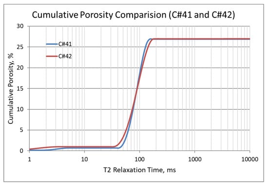
Figure 6.
NMR cumulative porosity comparison between C#41 and C#42.
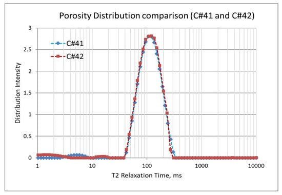
Figure 7.
NMR porosity distribution comparison between C#41 and C#42.
In the subsequent phase of oil displacement, CSW as floodwater resulted in 4.53% additional recovery from C#41 compared to 9.38% recovery from C#42 when CESW is the displacing fluid. Approximately 5% more recovery by CESW can be attributed to the synergic effect of CO2 and sulfate in the floodwater. In the 24 h exposure stage, however, the recovery with CESW is about 2% less than the CSW, possibly due to reaching the limit of recoverable oil at the earlier stage of the floods. However, it may be noticed that the cumulative recovery of C#42 is about 2% more than C#41, which is likely due to the presence of sulfate ions spiked in the CESW.
NMR porosity studies: NMR porosity distribution (PSD) and cumulative porosity (CP) for the test core plugs were measured before and after the completion of corefloods. From the comparative NMR-PSD plot of C#33 (Figure 8), it was observed that post-flood PSD is significantly different from PSD plots before the coreflood. Pores are enlarged considerably in the macro-region and reduced slightly in the micro-pore region. The core plug’s cumulative porosity (Figure 9) increased to 22.76% from 20.45%. The incremental porosity in the macro-region is due to carbonic acid’s dissolution of calcium and magnesium compounds, which will be discussed later with ICP-MS results. The minor reduction in the micro-region could be due to the precipitation of the sulfate scale. Similar results could be seen in the case of a lower-permeability core plug (C#198); however, the differences are not as significant as the higher-permeability core plug (Figure 10 and Figure 11). Cumulative porosity was increased only by 0.5%, which is not significant enough for any conclusion.
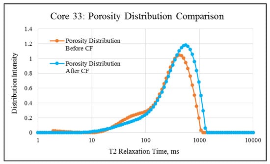
Figure 8.
NMR porosity distribution comparison of C#33: before and after the coreflood.
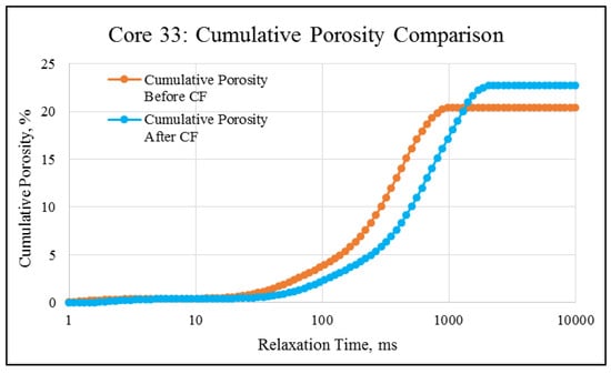
Figure 9.
NMR cumulative porosity comparison of C#33: before and after the coreflood.
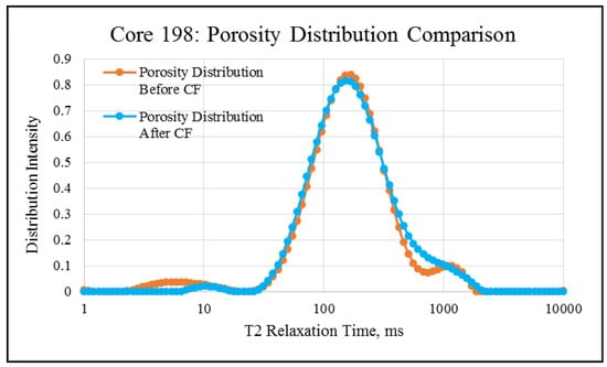
Figure 10.
NMR porosity distribution comparison of C#198: before and after the coreflood.
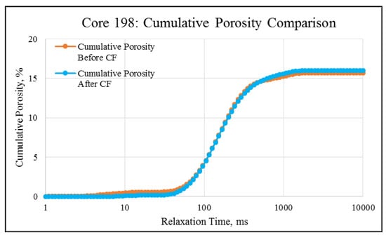
Figure 11.
NMR cumulative porosity comparison of C#198: Before and after the coreflood.
ICP-MS Analysis: Effluents from each mode of the coreflood were subjected to ICP-MS compositional analysis to compare pre-and post-flood concentrations of significant and potential determining ions (PDI) viz. magnesium, calcium, and sulfate. In carbonate-rock- and sulfate-rich aqueous systems, the potential of the surface is determined by the activity of these ions because they can either dissolve or deposit on the rock surface, influencing the surface potential [52]. The ICP-MS study was vital in discerning the rock dissolution process during flooding [53]. ICP analysis of injection and produced brine from CF-1 and CF-2 are presented in graphical form in Figure 12, Figure 13, Figure 14, Figure 15, Figure 16 and Figure 17.
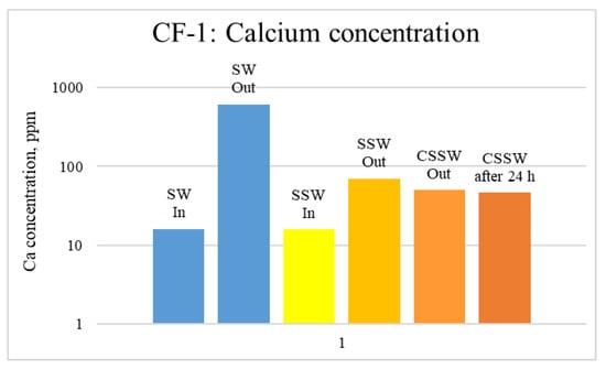
Figure 12.
ICP analysis of CF1 brines: Calcium concentration.
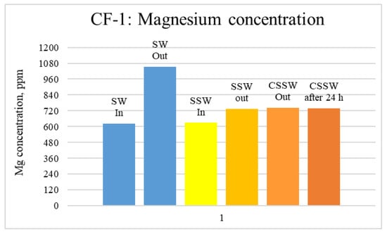
Figure 13.
ICP analysis of CF1 brines: Magnesium concentration.
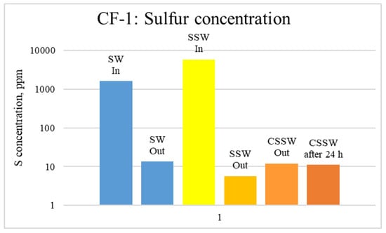
Figure 14.
ICP analysis of CF1 brines: Sulfur concentration.
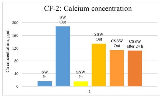
Figure 15.
ICP analysis of CF-2 brines: Calcium concentration.
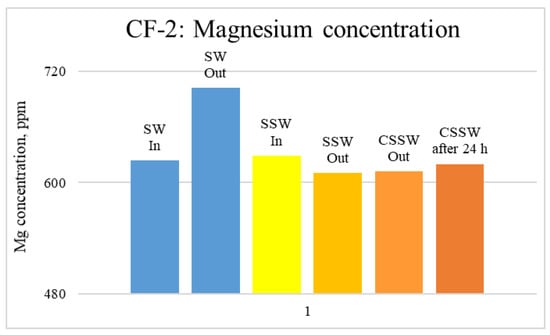
Figure 16.
ICP analysis of CF-2 brines: Magnesium concentration.
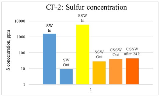
Figure 17.
ICP analysis of CF-3 brines: Sulfur concentration.
Figure 12, Figure 13 and Figure 14 depict Mg, S, and Ca concentrations in injection and effluent brines in CF-1. Figure 12 and Figure 13 show a significant increase in Ca and Mg ion concentration in produced brine compared to the injection brine (SW). Since seawater is severely under-saturated with Ca and Mg ions, this dissolution was expected and a possible reason for high oil recovery in the secondary recovery stage. Here, seawater may act as low-salinity water because its salinity is nearly one-fourth of that of the formation water. In addition, during the tertiary and quaternary recovery stages, Ca and Mg ions are higher in produced water than in the base water. (It should be kept in mind that Ca and Mg concentration in CESW is the same as SW.) This must have resulted from the continuous dissolution of these ions during all three modes of oil recovery. At the same time, sulfur concentration is found in reduced concentration (Figure 14) at all stages of flooding compared to its concentration in injected brine. Similar results are observed from the brine analysis of CF-2, in which the positively charged ions (Ca and Mg) are dissolved in all flood modes, resulting in significantly higher concentration in the produced brine compared to injection brine (Figure 15 and Figure 16). Simultaneously, negatively charged sulfate ions are deposited on the positively charged carbonate rock, resulting in a reduced concentration of sulfur in the produced brine (Figure 17).
4. Discussion
The overall results and ultimate oil recovery by the brines used in this study suggest that multiple factors are responsible for the enhanced oil recovery. The oil properties show that the crude oil has an appreciable acidic fraction along with other polar components, such as resins and asphaltenes, which facilitate the oil-wetting characteristics of carbonate rocks. IFT and contact angle are two critical rock–fluid properties that facilitate oil entrapment or release from the pore spaces. As reported by many authors, lowering IFT and converting the oil-wet rock into water or intermediate wet helps to desorb and release the oil blobs. In the present case, IFT was reduced insignificantly when the water phase was ESW but decreased by nearly 300% when CO2 was dissolved in ESW, causing a synergic effect. However, this reduction is insufficient to release a significant percentage of trapped oil.
In comparison, the contribution from wettability alteration may be more significant in this case. ESW and CESW altered the core wettability from distinctly oil wet to intermediate wet, of which CESW was able to bring the rock wettability closer to water wet. CSW is seen to be less potent in terms of wettability alteration. It is well-known that altering wettability from oil wet to intermediate/water wet helps in the brine imbibition process and enhances oil recovery [54].
The other significant aspect that could be attributed to the release of trapped oil is the ion-exchange process between rock minerals and brine. NMR porosity and ICP-MS ion analysis result clearly demonstrated the dissolution of Ca and Mg ions not only during secondary recovery but during all the flood modes, which resulted in pore enlargement as evidenced in NMR-PSD and NMR-CP. The ICP-MS analysis also proved the deposition of sulfate ions on the pore walls, as sulfur in the produced water is 100 times lesser than in the injection water. Hiorth A. et al. [55] built a chemical model coupling bulk aqueous and surface chemistry and predicted the ion-exchange phenomena and the resulting impact on wettability and oil desorption. Their study shows that the adsorption of positively charged major ions (Ca2+ and Mg2+) on the rock surface promotes oil wetting, and their dissolution would promote water waiting. Furthermore, the water-wetting characteristics will be enhanced if a negative surface charge is created through SO42− deposition. Thus, the amount of Ca2+ and Mg2+ ions dissolved and SO42− deposited (in the present study) could very well account for the extra oil production during the ESW flood. This sulfate-exchange phenomenon is recognized as the primary mechanism of the release of trapped oil by engineered water by Sarvestani et al. [43] and others [56] who evidenced deposition CaSO4 on the rock surface.
Comparing the recovery factors in the first set of coreflood studies, it was observed that significantly more oil is produced when CO2 was dissolved in ESW compared to ESW flood alone. Cumulatively, the instantaneous and 24 h of exposure to CESW generated a recovery factor of 11.14% and 6.55% compared to 0.66% and 1.14% through ESW flood in C#33 and C#198. The second set of coreflood, intended to study the impact of sulfate and CO2 separately, demonstrated that whereas CSW recovered 12.16% additional oil, CESW recovered 15.27%. The extra 3% recovery must be due to sulfate-exchange phenomena and the resulting synergic effect. In a recent study, Soleimani et al. [25] observed a similar result. When CO2 is dissolved in low-salinity and high-salinity water injection, the recovery factor was always more than the time when CO2 was not dissolved in injection water. However, the impact of CO2 was more when low-salinity water was used.
Thus, the results obtained through this study prove that CWI with CO2 in the dissolved form (i.e., CO32− and HCO3−) in brine and diffused CO2 in oil can be more efficient in oil displacement than engineered water with spiked sulfate ions alone. Another significant advantage of carbonated water could be its ability to arrest scaling due to the dissolved acid gas. On pore-scale investigation using a scanning electron microscope, Ghasemian and Riahi [56] observed precipitation of CaSO4− CaCO3 composite scale while injecting sulfate-rich seawater. The scale crystals grew perpendicular to the pore wall, and severe permeability loss was observed, which could be detrimental, particularly in tight formations. However, in the presence of CO2, the solubility of carbonate minerals increases, and scaling is arrested [57]. Despite the benefits of hybridized carbonated engineered water described above, further investigations and reservoir scale simulation must be performed to evaluate its actual potential in terms of technology and economics prior to field pilots.
5. Conclusions
In this study, the individual and synergic potency of engineered water and carbonated water was investigated. Performance of the individual waters and the hybrid carbonated engineered water were evaluated through high-pressure, high-temperature interfacial tension and contact angle and coreflood recovery studies. Before and after the corefloods, changes in pore size and size distribution were measured using NMR-T2 signal analysis. Mineral dissolution and depositions were quantitatively determined through ICP-MS studies of the injection and effluent waters. The studies were performed under the condition of a carbonate reservoir in the Middle East, using core plugs, crude oil, and brine composition of the same field. The following conclusions are drawn from this study:
- Coreflood recovery studies revealed that the ESW has less impact on recovering oil compared to CESW. Cumulatively, the instantaneous and 24 h of exposure to CESW improved recovery by 11.14% and 6.55% compared to 0.66% and 1.14% through ESW flood in high-permeability and low-permeability core plugs, respectively.
- Carbonated water with and without sulfate (i.e., CSW and CESW) was evaluated for oil recovery efficiency. The results show cumulative recovery in CSW flood is 12.16%, whereas for CESW, the additional recovery is 15.27%. The extra 3% recovery is attributed to the presence of sulfate and the resulting synergic effect.
- IFT reduction by ESW, CSW, and CESW is approximately 10%, 40%, and 70%, respectively. This reduction may have a very little contribution on its own in releasing trapped oil; however, the alteration of wettability towards intermediate wet for ESW and CSW and close to water wet for CESW may be one of the significant factors for additional oil recovery.
- Dissolution of calcium and magnesium and deposition of sulfate ions during all the flood modes are proven by the difference in these ion concentrations in injection and production brines, which resulted in a net pore enlargement, as evidenced in NMR-PSD and NMR-CP. This sulfate-exchange phenomenon is recognized as the primary mechanism of release of trapped oil by engineered water by Sarvestani et al. [43] and many others.
- Multiple factors are attributed to the possible mechanism behind the additional oil recovery with carbonated engineered water flooding. The most significant among them is the exchange of PDIs, which resulted in rock dissolution, sulfate deposition, and release of stuck oil. Improving the mobility ratio due to oil viscosity reduction by CO2, swelling, and reconnection of oil blobs are also contributing factors. The pore size distribution and ionic composition studies of the injected brine and effluent analysis indicate that rock dissolution occurred after flooding the core plugs with carbonated engineered water.
Author Contributions
Conceptualization, B.G. and A.K.; methodology, B.G., A.K. and N.C.T.; software, A.K. and N.C.T.; validation, B.G., M.H., M.M.R. and H.B.; formal analysis, A.K. and N.C.T.; investigation, A.K. and N.C.T.; resources, B.G.; data curation, M.H. and M.M.R.; writing—original draft preparation, B.G., A.K; writing—review and editing, B.G., A.K., N.C.T., M.H., M.M.R. and H.B.; visualization, B.G.; supervision, B.G. All authors have read and agreed to the published version of the manuscript.
Funding
This research received no external funding.
Acknowledgments
The authors acknowledge Khalifa University, Abu Dhabi, UAE, for the support and encouragement provided in undertaking this study.
Conflicts of Interest
The authors declare no conflict of interest.
Nomenclature
| CF | Coreflooding |
| CO2 | Carbon dioxide |
| CP | Cumulative porosity |
| CESW | Carbonated engineered seawater |
| CWI | Carbonated water injection |
| EOR | Enhanced oil recovery |
| ESW | Sea water with four times sulfate ions (engineered sea water) |
| IFT | Interfacial tension |
| MIE | Multicomponent ionic exchange |
| MMP | Minimum miscibility pressure |
| NMR | Nuclear magnetic resonance |
| PSD | Porosity distribution |
| PDI | Potential determining ions |
| PV | Pore volume |
| SW | Seawater |
| RF | Recovery factor |
| Sor | Residual oil saturation |
| Swirr | Irreducible water saturation |
References
- Chavan, M.; Dandekar, A.; Patil, S.; Khataniar, S. Low-salinity-based enhanced oil recovery literature review and associated screening criteria. Pet. Sci. 2019, 16, 1344–1360. [Google Scholar] [CrossRef]
- Aljuboori, F.A.; Lee, J.H.; Elraies, K.A.; Stephen, K.D. Gravity drainage mechanism in naturally fractured carbonate reservoirs; review and application. Energies 2019, 12, 3699. [Google Scholar] [CrossRef]
- Chilingar, G.; Yen, T.F. Some notes on wettability and relative permeability of carbonate reservoir rock. Energy Sources 1992, 7, 21–27. [Google Scholar] [CrossRef]
- Cheraghian, G.; Tardast, S. Improved Oil Recovery by the Efficiency of Nano-particle in Imbibition Mechanism. In Proceedings of the the 2nd EAGE International Conference KazGeo, Almaty, Kazakhstan, 29–31 October 2012. [Google Scholar]
- Zhang, H.; Nikolov, A.; Wasan, D.T. Enhanced Oil Recovery (EOR) Using Nanoparticle Dispersions: Underlying Mechanism and Imbibition Experiments. Energy Fuels 2014, 28, 3002–3009. [Google Scholar] [CrossRef]
- Kilybay, A.; Ghosh, B.; Thomas, N.C.; Aras, P. Hybrid EOR Technology: Carbonated Water and Smart Water Improved Recovery in Oil Wet Carbonate Formation. In Proceedings of the SPE Caspian Annual Technical Conference & Exhibition, Astana, Kazakhstan, 1–3 November 2016. [Google Scholar]
- Kilybay, A.; Ghosh, B.; Thomas, N.C.; Sulemana, N.T. Hybrid EOR Technology: Carbonated Water-Smart Water Flood Improved Recovery in Oil Wet Carbonate Formation: Part-II. In Proceedings of the SPE Oil and Gas India Conference and Exhibition, Mumbai, India, 4 April 2017. [Google Scholar]
- Yongmao, H.; Zenggui, W.; Binshan, J.; Yueming, C.; Xiangjie, L.; Petro, X. Laboratory Investigation of CO2 Flooding. In Proceedings of the Nigeria Annual International Conference and Exhibition, Abuja, Nigeria, 2 August 2004. [Google Scholar]
- Yousef, A.A.; Al-Salehsalah, S.H.; Al-Jawfi, M.S. New Recovery Method for Carbonate Reservoirs through Tuning the Injection Water Salinity: Engineered WaterFlooding. In Proceedings of the SPE EUROPEC/EAGE Annual Conference and Exhibition, Vienna, Austria, 23 March 2011. [Google Scholar]
- Puntervold, T.; Mamonov, A.; Torrijos, I.D.P.; Strand, S. Adsorption of Crude Oil Components onto Carbonate and Sandstone Outcrop Rocks and Its Effect on Wettability. Energy Fuels 2021, 35, 5738–5747. [Google Scholar] [CrossRef]
- Mamonov, A.; Aslanidis, P.; Fazilani, N.; Puntervold, T.; Strand, S. Influence of Sandstone Mineralogy on the Adsorption of Polar Crude Oil Components and Its Effect on Wettability. Energy Fuels 2022, 36, 10785–10793. [Google Scholar] [CrossRef]
- Bartels, W.B.; Mahani, H.; Berg, S.; Hassanizadeh, S.M. Literature review of low salinity waterflooding from length and time scale perspective. Fuel 2019, 236, 338–353. [Google Scholar] [CrossRef]
- Ayirala, S.C.; Li, Z.; Saleh, S.H.; Xu, Z.; Yousef, A.A. Effects of salinity and individual ions on crude-oil/water interface physicochemical interactions at elevated temperature. SPE Res. Eval. Eng. 2019, 22, 897–910. [Google Scholar] [CrossRef]
- Al-Shalabi, E.W.; Sepehrnoori, K. A comprehensive review of low salinity/engineered water injections and their applications in sandstone and carbonate rocks. J. Pet. Sci. Eng. 2016, 139, 137–161. [Google Scholar] [CrossRef]
- Katende, A.; Sagala, F. A critical review of low-sal water flood: Mechanism, laboratory and field application. J. Mol. Liq. 2019, 278, 627–649. [Google Scholar] [CrossRef]
- Adegbite, J.O.; Al-Shalabi, E.W.; Ghosh, B. Modelling the Effect of Engineered Water Injection on Oil Recovery from Carbonate Cores. In Proceedings of the SPE International Conference on Oilfield Chemistry, Montgomery, TX, USA, 3–5 April 2017. [Google Scholar]
- Adegbite, J.O.; Al-Shalabi, E.W.; Ghosh, B. Geochemical Modeling of Engineered Water Injection Effect on Oil Recovery from Carbonate Cores. J. Pet. Sci. Eng. 2018, 170, 696–711. [Google Scholar] [CrossRef]
- Adegbite, J.O.; Al-Shalabi, E.W.; Ghosh, B. Field Application of Engineered Water Injection in Carbonate Reservoirs under Permeability Channeling and Gravity Underride Conditions. In Proceedings of the SPE International Conference and Exhibition on Formation Damage Control, Lafayette, Ca, USA, 7–9 February 2018. [Google Scholar]
- Ayirala, S.C.; Saleh, S.; Enezi, S.; Yousef, A. Multiscale aqueous-ion interactions at interfaces for enhanced understanding of controlled-ionic-composition-waterflooding processes in carbonates. SPE Res. Eval. Eng. 2020, 23, 1118–1132. [Google Scholar] [CrossRef]
- Meng, W.; Haroun, M.R.; Sarma, H.K.; Adeoye, J.T.; Aras, P.; Punjabi, S.; Rahman, M.M.; Al Kobaisi, M. A Novel Approach of Using Phosphate-spiked Smart Brines to Alter Wettability in Mixed Oil-Wet carbonate Reservoirs. In Proceedings of the Abu Dhabi International Petroleum Exhibition and Conference, Abu Dhabi, United Arab Emirates, 9–12 November 2015. [Google Scholar]
- Tetteh, J.T.; Barati, R. Crude-oil/brine interaction as a recovery mechanism for low-salinity waterflooding of carbonate reservoirs. SPE Res. Eval. Eng. 2019, 22, 877–896. [Google Scholar] [CrossRef]
- Riazi, M.; Sohrabi, M.; Jamiolahmady, M.; Ireland, S.; Brown, C. Oil Recovery Improvement Using CO2-Enriched Water Injection. In Proceedings of the EUROPEC/EAGE Conference and Exhibition, Amsterdam, The Netherlands, 8–11 June 2009. [Google Scholar]
- Ghosh, B.; Al-Hamairi, A.; Jin, S. Carbonated water injection: An efficient EOR approach. A review of fundamentals and prospects. J. Pet. Explor. Prod. Technol. 2020, 10, 673–685. [Google Scholar]
- Ajoma, E.; Sungkachart, T.; Yin, H.; Le-Hussain, F. A laboratory study of coinjection of water and CO2 to improve oil recovery and CO2 storage: Effect of fraction of CO2 Injected. SPE J. 2021, 26, 2139–2147. [Google Scholar] [CrossRef]
- Soleimani, P.; Shadizadeh, S.R.; Kharrat, R. Experimental assessment of hybrid Engineered carbonated water flooding for carbonate reservoirs. Petroleum 2021, 7, 80–90. [Google Scholar] [CrossRef]
- Sohrabi, M.; Riazi, M.; Jamiolahmady, M.; Ireland, S.; Brown, C. Mechanisms of Oil Recovery by Carbonated Water Injection. In Proceedings of the International Symposium of the Society of Core Analysts, Pau, France, 26–30 August 2019. [Google Scholar]
- Chang, Y.B.; Coats, B.K.; Nolen, J.S. A Compositional Model for CO2 Floods Including CO2 Solubility in Water. SPE Res. Eval. Eng. 1998, 1, 155–160. [Google Scholar] [CrossRef]
- Duan, Z.; Sun, R.; Zhu, C.; Chou, I.M. An improved model for the calculation of CO2 solubility in aqueous solutions containing Na+, K+, Ca2+, Mg2+, Cl− and SO42−. Mar. Chem. 2006, 98, 131–139. [Google Scholar] [CrossRef]
- Farokhpoor1, R.; Sundal, L.; Skjærstein, A.; Hebing, A.; Zhang, X.; Pirlea, L. Core cleaning and wettability restoration—selecting appropriate method. In Proceedings of the 35th International Symposium of the Society of Core Analysts, Austin, TX, USA, 19–22 September 2022. [Google Scholar]
- Yan, W.; Sun, J.; Sun, Y.; Golsanami, N. A robust NMR method to measure porosity of low porosity rocks. Microporous Mesoporous Mater. 2018, 269, 113–117. [Google Scholar] [CrossRef]
- Elsayed, M.; Isah, A.; Hiba, M.; Hassan, A.; Al-Garadi, K.; Mahmoud, M.; El-Husseiny, A.; Radwan, A.E. A review on the applications of nuclear magnetic resonance (NMR) in the oil and gas industry: Laboratory and field-scale measurements. J. Petrol. Explor. Prod. Technol. 2022, 12, 2747–2784. [Google Scholar] [CrossRef]
- Riazi, M.; Golkari, A. The influence of spreading coefficient on carbonated water alternating gas injection in heavy crude oil. Fuel 2016, 178, 1–9. [Google Scholar] [CrossRef]
- Stalder, A.F.; Kulik, G.; Sage, D.; Barbieri, L.; Hoffmann, P. A snake-based approach to accurate determination of both contact points and contact angles. Colloids Surf. A Physicochem. Eng. Asp. 2006, 286, 92–103. [Google Scholar] [CrossRef]
- Al-Mutairi, S.M.; Abu-Khamsin, S.A.; Okasha, T.M.; Hossain, M.E. An experimental investigation of wettability alteration during CO2 immiscible flooding. J. Pet. Sci. Eng. 2014, 120, 73–77. [Google Scholar] [CrossRef]
- Seyyedi, M.; Sohrabi, M.; Farzaneh, A. Investigation of Rock Wettability Alteration by Carbonated Water through the Contact Angle Measurements. Energy Fuels 2015, 29, 5544–5553. [Google Scholar] [CrossRef]
- Taiane, R.P.; Almeida, J.R.; Sousa, R.M.; Ribeiro, E.V.; Carneiroa, M.T.; Brandão, G.P. Multielement analysis of crude oil produced water by ICP OES after acid digestion assisted by microwave. J. Anal. At. Spectrom. 2015, 30, 1154–1160. [Google Scholar]
- Aoudia, M.; Al-Shibli, M.N.; Al-Kasimi, L.H.; Al-Maamari, R.; Al-bemani, A. A novel surfactant for ultralow interfacial tension in a wide range of surfactant concentration and temperature. J. Sur. Det. 2006, 9, 287–293. [Google Scholar] [CrossRef]
- Bachu, S.; Bennion, D.B. Interfacial tension between CO2, freshwater, and brine in the range of pressure from (2 to 27) MPa, temperature from (20 to 125) °C, and water salinity from (0 to 334,000) mg/L−1. J. Chem. Eng. Data. 2009, 54, 765–775. [Google Scholar] [CrossRef]
- Morteza, R.; Lashkarbolooki, M. Activation of carbonated brine with surfactants and sulfate anion for enhanced oil recovery processes. Fuel 2022, 329, 125352. [Google Scholar]
- Yang, Z.; Liu, X.; Hua, Z.; Ling, Y.; Li, M.; Lin, M.; Dong, Z. Interfacial tension of CO2 and crude oils under high pressure and temperature. Colloids Surf. A Physicochem. Eng. Asp. 2015, 482, 611–616. [Google Scholar] [CrossRef]
- Habibi, S.; Jafari, A.; Fakhroueian, Z. Wettability alteration analysis of engineered water/novel functionalized nanocomposites for enhanced oil recovery. Pet. Sci. 2020, 17, 1318–1328. [Google Scholar] [CrossRef]
- Mahani, H.; Menezes, O.R.; Berg, S.; Fadili, A.; Nasralla, R.; Voskov, D.; Joekar-Niasar, V. Insights into the Impact of Temperature on Wettability Alteration by Low-Salinity in Carbonate Rocks. Energy Fuels 2017, 31, 7839–7853. [Google Scholar] [CrossRef]
- Sarvestani, A.D.; Ayatollahi, S.; Moghaddam, M.B. Engineered water flooding performance in carbonate reservoirs: An experimental approach for tertiary oil recovery. J. Pet. Explor. Prod. Technol. 2019, 9, 2643–2657. [Google Scholar] [CrossRef]
- Mahani, H.; Keya, A.L.; Berg, S.; Bartels, W.B.; Nasralla, R.; Rossen, W.R. Insights into the Mechanism of Wettability Alteration by Low-Salinity Flooding (LSF) in Carbonates. Energy Fuels 2015, 29, 1352–1367. [Google Scholar] [CrossRef]
- Ruidiaz, E.M.; Winter, A.; Trevisan, O.V. Oil recovery and wettability alteration in carbonates due to carbonate water injection. J. Pet. Explor. Prod. Technol. 2018, 8, 249–258. [Google Scholar] [CrossRef]
- Seyyedi, M.; Sohrabi, M. Enhancing Water Imbibition Rate and Oil Recovery by Carbonated Water in Carbonate and Sandstone Rocks. Energy Fuels 2016, 30, 285–293. [Google Scholar] [CrossRef]
- Vadhan, R.S.; Phukan, R. Carbonated Smart Water Injection for Enhanced Oil Recovery in Sandstone Reservoirs of Upper Assam Basin, India. In Proceedings of the SPE EuropEC-Europe Energy Conference Featured at the 83rd EAGE Annual Conference & Exhibition, Madrid, Spain, 9 June 2022. [Google Scholar]
- Mahani, H.; Berg, S.; Ilic, D.; Bartels, W.B.; Joekar-Niasar, V. Kinetics of Low-Salinity-Flooding Effect. SPE. J. 2014, 20, 8–20. [Google Scholar] [CrossRef]
- Ansari, A.A.; Haroun, M.; Rahman, M.M.; Chilingar, G.V. Increasing depth of penetration by electrokinetic driven low-concentration acid IOR in Abu Dhabi tight carbonate reservoirs. In Proceedings of the Abu Dhabi International Petroleum Exhibition and Conference, Abu Dhabi, United Arab Emirates, 10–13 November 2014. [Google Scholar]
- Ansari, A.A.; Haroun, M.; Rahman, M.M.; Chilingar, G.V. Electrokinetic Driven Low-Concentration Acid Improved Oil Recovery in Abu Dhabi Tight Carbonate Reservoirs. Electrochim. Acta 2015, 181, 255–270. [Google Scholar] [CrossRef]
- Jamaloei, B.Y.; Kharrat, R. Analysis of Microscopic Displacement Mechanisms of Dilute Surfactant Flooding in Oil-wet and Water-wet Porous Media. Transp. Porous Med. 2010, 81, 1. [Google Scholar] [CrossRef]
- Shirazi, M.; Farzaneh, J.; Kord, S.; Tamsilian, Y. Smart water spontaneous imbibition into oil-wet carbonate reservoir cores: Symbiotic and individual behavior of potential determining ions. J. Mol. Liq. 2020, 299, 112102. [Google Scholar] [CrossRef]
- Kono, F.; Kato, A.; Shimokawara, M.; Tsushima, K. Laboratory Measurements on Changes in Carbonate Rock Properties due to CO2-Saturated Water Injection. In Proceedings of the Abu Dhabi International Petroleum Exhibition and Conference, Abu Dhabi, United Arab Emirates, 10–13 November 2014. [Google Scholar]
- Andersen, P.O.; Sameer Ahmed, S. Simulation study of wettability alteration enhanced oil recovery during co-current spontaneous imbibition. J. Pet. Sci. Eng. 2021, 196, 107954. [Google Scholar] [CrossRef]
- Hiorth, A.; Cathles, L.M.; Madland, M.V. The Impact of Pore Water Chemistry on Carbonate Surface Charge and Oil Wettability. Transp. Porous Med. 2010, 85, 1–21. [Google Scholar] [CrossRef]
- Ghasemian, J.; Riahi, S. Effects of salinity and ionic composition of smart water on mineral scaling in carbonate reservoirs during water flooding. Pet. Explor. Dev. 2021, 48, 421–429. [Google Scholar] [CrossRef]
- Crabtree, M.; Eslinger, D.; Fletcher, P.; Miller, M.; Johnson, A.; King, G. Fighting Scale—Removal and Prevention. Oilfield Rev. 1999, 11, 30–45. [Google Scholar]


Publisher’s Note: MDPI stays neutral with regard to jurisdictional claims in published maps and institutional affiliations. |
© 2022 by the authors. Licensee MDPI, Basel, Switzerland. This article is an open access article distributed under the terms and conditions of the Creative Commons Attribution (CC BY) license (https://creativecommons.org/licenses/by/4.0/).