Article

Study on Induced Voltage and Circulation Current of Metal Layer in Single-Core Cable of High-Speed Railway Power Transmission Line

1
China Railway First Survey and Design Institute Group Co., Ltd., Xi’an 710043, China
2
School of Electrical Engineering, Beijing Jiaotong University, Beijing 100044, China
*
Author to whom correspondence should be addressed.
Energies 2022, 15(14), 5010; https://doi.org/10.3390/en15145010
Submission received: 24 May 2022 / Revised: 4 July 2022 / Accepted: 4 July 2022 / Published: 8 July 2022
(This article belongs to the Special Issue Studies in the Energy Efficiency and Power Supply for Railway Systems)

Abstract

:
The metal shield and metal armor layers of single-core cables on high-speed railroad power penetration lines are usually grounded by common equipment protectors. This grounding method brings a continuous circulating current between the metal shield and metal armor layer compared to the subequipment protection grounding. In order to quantitatively study the circulating current condition of the through line and its influence on the reliability of the railroad power through line, the induced electric potential and circulating current generation mechanism of the single-core cable of the through line and its influencing factors were firstly analyzed in depth. Then, based on the cross-sectional structure of the single-core cable and the location of the traction network and cable in the roadbed section, a traction power supply model was established and simulated for the interlayer-induced potentials and circulating currents due to the two grounding protection methods under no load, single train operation, and heavy load four-train operation of the line. Finally, three actual sections of the Shanghai–Kunming and Nan–Kunming high-speed railroads in China were selected to collect and analyze the loop flow data with no load and with vehicles passing through, and finally the loop flow law of single-core cable for railroad electric through traffic was derived. The analysis shows that when the metal sheath of a single-core cable is grounded by ordinary equipment, the circulating current generated does not exceed 1% of the core current, which meets the relevant safety standards, but the induced voltage in the case of large loads will exceed 50 V safety voltage.

1. Introduction

With the continuous opening of high-speed railroads, railroad operation and maintenance management are becoming more and more perfect, and the requirements for safe operation of equipment are also becoming higher and higher. In order to ensure the reliability of power supply, the power through lines all use single-core cables, and for the power through cable protection grounding problem, scholars have performed a lot of research. The literature [1] proposes that the metal shield and metal armor layer of single-core cables of transmission lines are grounded directly at one end and grounded with a common equipment sheath protector at the other end. The literature [2] proposes that to prevent cable induction, electromotive force should be taken to be laid in an equilateral triangle, and the continuous length of the metal layer of the cable is controlled within 3km. The literature [3] investigates the structural and physicochemical properties of multistranded single-core through wires for the study of induced potential in railroad power through wires. In the literature [4], shock hazard and voltage stress of the nonmetallic outer sheath of cables are evaluated. The literature [5] investigates the calculation of induced voltages in multiple circuits of cables and proposes a new method for the calculation of induced voltages in metal shields of three-circuit, single-core power cables. The literature [6] analyzes the sheath voltage and current of HVDC cables, considering different cable lengths and sheath grounding schemes. The literature [7,8] proposes a single-core cable sheath overvoltage analysis method and suppression measures considering harmonics and inrush currents. The literature [9] presents a simulation model to evaluate the magnitude and distribution of induction armor/sheath currents in medium- and high-voltage cables, which can be used to optimize high current industrial applications. The literature [10] found that when a single-core cable conductor passes through an AC current, an AC magnetic field is generated around the cable, generating an induced voltage above the metal shield and the metal armor layer. However, its quantitative relationship between the induced voltage and current has not been studied in depth. The literature [11] studied single-core cable, sheath-induced voltage and found the law of metal sheath-induced voltage, but its results were not confirmed by relevant experiments for the availability in high-speed railroad systems. To further quantify the relationship between the magnitude of induced voltage and current value, cable arrangement, and cable length and to make an effective assessment of the safety of railroads and common equipment protection grounding nowadays for the circulating current problem of railroad power through lines, this paper makes an in-depth analysis of single-core cable induction potential based on actual railroad sections and combines simulation experiments to quantitatively study the characteristics of circulating current and induction potential under the common equipment protection grounding mode of power through lines.

2. Theory

2.1. Theoretical Calculation of Induction Voltage

P is a conductor in space, parallel to the three-phase cores A, B, and C; the distances between p and the three-phase cable cores are D, βD, and γD, and the distances among the three-phase cable cores are S, mS, and nS, which are shown in Figure 1.
According to the law of electromagnetic induction, the total magnetic flux (w/km) between conductor p and the three-phase cable cores A, B, and C is
φ p = 2 × 10 4 I ˙ A ln D GMR p + I ˙ B ln β D GMR p + I ˙ C ln γ D GMR p
where GMRP is the geometric mean radius of conductor p in the same units as D and m; İA, İB, and İC are the core currents, A.
The longitudinal-induced voltage per unit length on conductor p (volts/km) is
E p = j ω φ p = j ω 2 × 10 4 I ˙ A ln D GMR p + I ˙ B ln β D GMR p + I ˙ C ln γ D GMR p
where ω is the angular frequency, rad/s, and the rest is the same as Equation (1).
Now, assume that the conductor p gradually moves to the line core A, and becomes concentric with A, that is, becomes the metal sheath of phase A, and at this time βD = S and γD = nS, so Equation (2) can be rewritten as follows:
E p = j ω 2 × 10 4 I ˙ A ln D GMR p + I ˙ B ln S GMR p + I ˙ C ln nS GMR p

2.2. Engineering Calculation of Induced Voltage

For engineering practice, the main concern is the amplitude of the induced voltage, according to the form of cable laying, when the three cables are arranged in an equilateral triangle, the amplitude of the induced voltage of the metal layer of the cable can be calculated by the following equation:
E p = 2 ω I ln D GMR A × 10 4
where ω is the angular frequency, rad/s; I is the core current, A; GMRA is the geometric mean radius of the single-core cable, m; and D is the cable arrangement spacing, m.
Taking a single-core cable with a laying length of 3 km and a cross-section of 95 mm2 as an example, it has a conductor diameter of 11 mm, a shield diameter of 23.28 mm, a shield thickness of 0.24 mm, an armor diameter of 25.48 mm, and an armor thickness of 0.2 mm. When the three cables are arranged in an equilateral triangle, the induced voltage of the metal shield layer and metal armor layer at different core currents is shown in Table 1.

2.3. Influence of Traction Power Supply System on the Induced Voltage of Metal Sheath of Single-Core Cable in Power Transmission Line

When there is another parallel circuit conductor near the single-core cable, the conductor will also generate an alternating magnetic field when passing an alternating current, so that the single-core cable parallel to it will generate induced voltage on top of the metal shield and metal armor layer [12].
The multiconductor and single-core cable of each phase core distance are shown in Figure 2.
A′, B′, and C′ are conductors in a space parallel to the single-core cables A, B, and C, and the distances from single-core cable A are pS, qS, and rS, as shown in Figure 3.
According to the law of electromagnetic induction, the increased magnetic flux (w/km) on the sheath of single-core cable A due to the nearby circuit is:
φ A = 2 × 10 4 I ˙ A ln pS GMR A + I ˙ B ln qS GMR A + I ˙ C ln rS GMR A
The increased longitudinal-induced voltage (volts/km) on the sheath of the single-core cable A is:
E A = j ω φ A = j ω 2 × 10 4 I ˙ A ln pS GMR A + I ˙ B ln qS GMR A + I ˙ C ln rS GMR A
The total longitudinal-induced voltage on the sheath of single-core cable A can be obtained by adding Equations (3) and (6):
E A = E p + E A

2.4. Engineering Calculations of Induced Voltage in an Electrified Environment

The electric railway traction network is mainly composed of contract wires, rails, return lines, and other multiple conductors; the induction voltage between it and single-core cables can refer to the calculation of multiconductor induction voltage; the induced voltage of a single-core cable is the superposition of the induction voltage generated by each conductor [13]. Considering that the characteristics of power supply traction are single-phase and return current, after clarifying the current distribution on each conductor of the traction network, when the traction power supply current and the single-core cable core current have the same phase, the calculation of the induction voltage amplitude increasing in the cable metal sheath can be simplified by the following equation:
E A = 2 ω I ln S GMR A k 1 ln S 1 GMR A k n ln S n GMR A × 10 4
where I′ is the traction current, A; GMRA is the geometric mean radius of the metal sheath of the cable, m; S is the distance between the contract wire and the cable, m; S1, n is the distance between the conductor bearing the return current and the cable, such as metals, return lines, etc., m; k1, n is the shunt coefficient of the conductor bearing the return current to the return current.
Due to the diversity and complexity of the traction power supply system, it is difficult to determine the value of k in engineering. In addition, the magnitude of the traction current is closely related to the density of traffic and the position of the train [14], so simulation is used to calculate the induced voltage of the cable metal sheath and analyze the influence of the traction current on the induction voltage of the cable metal sheath.

3. Simulation and Experimental Methods

3.1. Simulation Model of Induced Voltage and Circulating Current of Metal Sheath of Single-Core Cable with Through Wire

High-speed railway traction power supply system generally adopts the AT power supply mode, and the traction network is mainly composed of carrier cables, contact wires, AF (positive feeder) lines, PW (protection) lines, rails, and integrated ground wires [15] whose position relationship with the single-core cable of the power transmission line is shown in Figure 3.
CDEGS (Current Distribution, Electromagnetic Fields, Grounding and Soil Structure Analysis) software can be used for accurate grounding and EMF analysis. CDEGS is used for simulation calculation, and the HIFREQ module is used for system modeling, and the simulation model is established in the module according to each wire suspension position in Figure 4, as shown in Figure 4.
Figure 4 shows the electromagnetic simulation model of the traction power supply system of the railroad line under the AT power supply mode in which the traction network and cable lines have been marked in the figure.
The structure of the single-core cable of the railroad through line is shown in Figure 5.
Define the parameters of each conductor in Table 2 and Table 3. Set the A phase cable core voltage, core current, and catenary voltage excitation phase to 0° in the simulation model; the single-core cable length is 3 km, and the metal sheath adopts a single-ended grounding method. Simulate and calculate the induced voltage of the shield layer and armor layer, as well as the circulating current when the shield and armor layer use a common sheath protector [16].
In order to study the variation of induced voltage and induced current of the metal sheath of the penetration line under different core loads, the induced voltage and circulating current of the cable protection layer using common equipment protective grounding and subequipment protective grounding methods were simulated in the case of no vehicle, single-vehicle, and four-vehicle passing intervals.

3.2. Experimental Method

In order to deeply analyze the induced potential and circulating current characteristics of the shielding layer of the high-speed railway power through line, three sections (named: “Hukun 1”, “Hukun 2”, and “Nankun 1”) were selected for testing on the Hukun and Nankun lines in China. The test equipment was a PQM16-D power quality monitoring system developed by Southwest Jiaotong University, as shown in Figure 6.
PQM16-D equipment can be a key device for real-time, high-precision comprehensive monitoring of the power system, with measurements, statistics, and analyses of power quality standards.
The test structure and equipment arrangement of the three sections “Hukun 1”, “Hukun 2”, and “Nankun 1” are shown in Figure 7, Figure 8 and Figure 9.
For “Hukun 2”, the grounding current at the grounded end of the 27.5 kV feeder cable, the induced voltage at the ungrounded end, and each electrical quantity at the substation were measured.
For “Hukun 1”, the core current of 10 kV power penetration line, induced voltage at the ungrounded end of 10 kV cable, grounding current at the ungrounded end of 10 kV cable, electrical quantities of traction substation, and the number of passing cars were measured.
For “Nankun 1”, the metal sheath grounding current of 170# and 171# cables and each electrical quantity of the traction substation were measured.

4. Results Analysis

4.1. Simulation Results and Analysis

There is no electric locomotive running in the interval. When the metal shield layer and armor layer of a single-core cable use a separate sheath protector [17], the induced voltage is shown in Table 4; when they use a common sheath protector, the induced voltage and circulating current are shown in Table 5; when the core current is 0, this means the power transmission line is in power-off maintenance.
As can be seen from Table 4 and Table 5, for the interval without locomotive operation, the single-core cable metal sheath-induced voltage is mainly affected by the core current, and is proportional to the core current. When the power transmission line loses power, the metal sheath-induced voltage can be almost negligible, so we can obtain a single-core cable that is buried and almost not affected by the traction power supply system with electrostatic coupling [18].
When the shield layer and armored layer are grounded with separate sheath protectors, due to the close distance between the shield layer and cable core, the induced voltage generated on the shield layer is larger than that on the armored layer; when the shield layer and armored layer are grounded with a common sheath protector, because both ends of the shield layer and armored layer are connected, the induced voltage of both is equal [19]. Regardless of whether the shield layer and armored layer are grounded with a separate or common sheath protector, when the core is the normal operating current of the transmission line, the normal induced voltage of the metal sheath is not greater than 50 V, which can satisfy the relevant regulations.
When the shield layer and armored layer are grounded with separate sheath protectors, there is no circulating current between them; when the shield layer and armored layer are grounded with a sheath protector together, there is a circulating current between them [20,21], and the circulating current does not exceed 1% of the load current, which is less than the relevant regulations.
Keep the cable position unchanged, and set up an electric locomotive at 7 km from the traction substation, and the locomotive takes the current of 960 A. When we adopt separate sheath protectors, we can obtain the metal sheath-induced voltage as shown in Table 6, and when we adopt a common sheath protector, the metal sheath-induced voltage and circulating current are shown in Table 7.
According to Table 6 and Table 7, the traction current has a greater effect on the induced voltage of the metal sheath of the single-core cable, the extent of which is much greater than the induced voltage generated by the core current, and the induced voltage exceeds the limit of 50 V safety voltage [22,23].
Since the armor layer is closer to the traction power supply system, the induced voltage generated by the traction power supply system on the armor layer is larger than the induced voltage on the shield layer, which leads to the reduction of the pressure difference between the shield layer and the armor layer [24], so the circulating current between the shield layer and the armor layer is slightly reduced instead, and the circulating current does not exceed 1% of the load current.
Keep the cable position unchanged, and set up an electric locomotive at 4 km from the traction substation in the up and down line of the power supply arm, respectively, and set up an electric locomotive in the up and down interval from the AT post to the section post [25], respectively, and the locomotives take the current of 960 A. Table 8 shows the metal sheath-induced voltage when set up with a separate sheath protector, and the metal sheath-induced voltage and circulating current when set up with a common sheath protector are shown in Table 9.
From Table 8 and Table 9, it can be seen that the metal sheath-induced voltage of single-core cable increases with the increase in traction current, and the increase in traction current has little effect on the pressure difference between the shield layer and armor layer [26,27]. Comparing Table 7 and Table 9, it can be seen that with the increase in traction current, the metal sheath-induced voltage increases, and the circulating current increases slightly [28], but still does not exceed 1% of the load current.
From the simulation data, it can be seen that the number of loaded vehicles on the line is positively correlated with the range of induced potential, and the induced potential and loop current of the cable sheath increases with the increase in the cable core current. Both grounding protection methods generate strong induced potential under the large load condition of four trains, which exceeds the safety threshold value, while the common equipment protection method has a loop current within the protection layer compared with the subequipment protection method, but under heavy load conditions, the loop current is less than 1% of the core load current, which is within the permissible range of the relevant index and meets the railroad stability requirements.

4.2. Experimental Results and Analysis

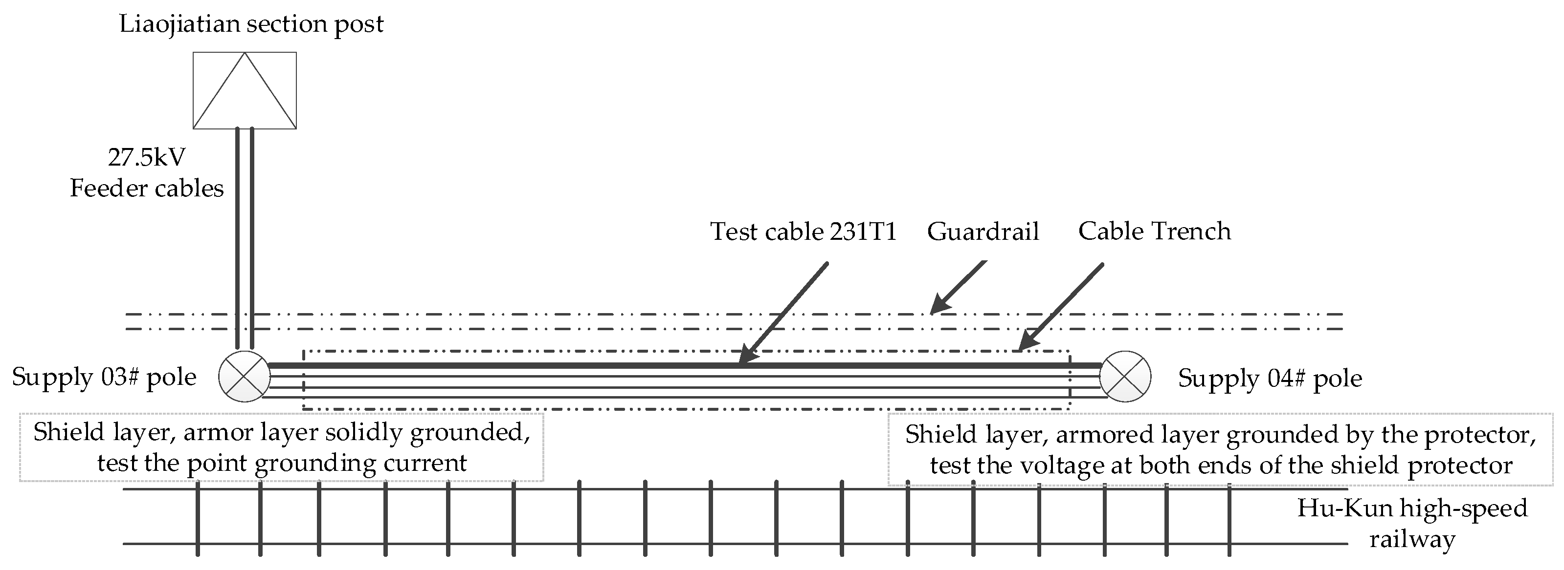
The “Hukun 1” section cable in the branch box adopts a shield layer and an armor layer direct grounding method, and the box change adopts the grounding method via a sheath protector. Test data from 10:00 to 10:30 during the test time were selected for analysis. 
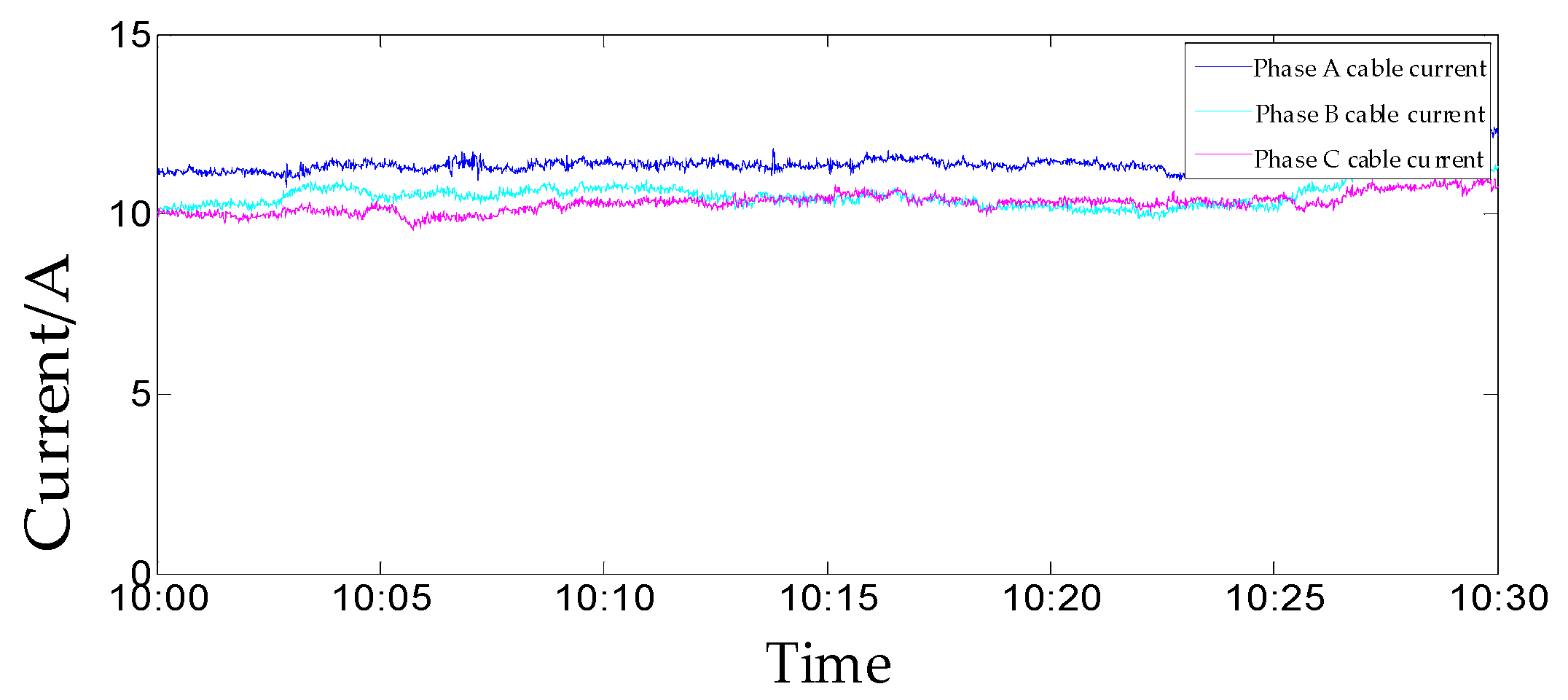
Figure 10 shows the current of 10 kV cable power through the cable core. 
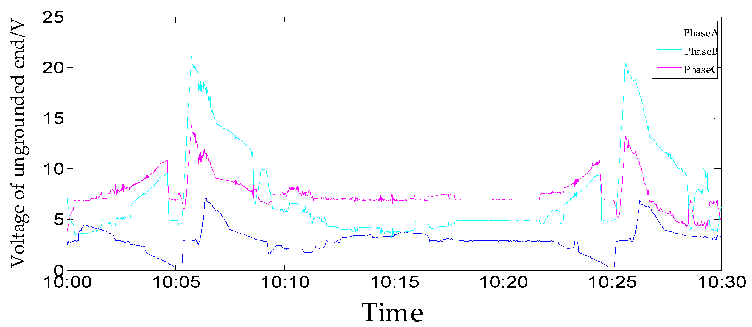
Figure 11 shows the voltage at both ends of the cable sheath protector. Figure 12 shows the current flowing through the armor layer at the nongrounding end.
From Figure 10, it can be seen that the three-phase load of the 10 kV power through line is basically equal, and the load current is about 10 A.
As can be seen from Figure 11, the induced voltage at the ungrounded end of the metal sheath varies with the load current and the current distribution of the traction power supply system, and the variation is large, up to 20 V.
From Figure 12, it can be seen that the circulating current in the armor layer and shield layer is about 37 mA and remains basically unchanged. This value is mainly affected by the cable core current, and the traction power supply system has less influence on it.
Comparing Figure 10, Figure 11 and Figure 12, we can see that the shield circulating current in the “Hukun 1” line is relatively small compared to the core current and is within the safe range. At the same time, the actual measurement results are consistent with the simulation results, which is convincing. The induced voltage between the shielding sheath of the through line is higher, about 20 V, which is also within the safe range.
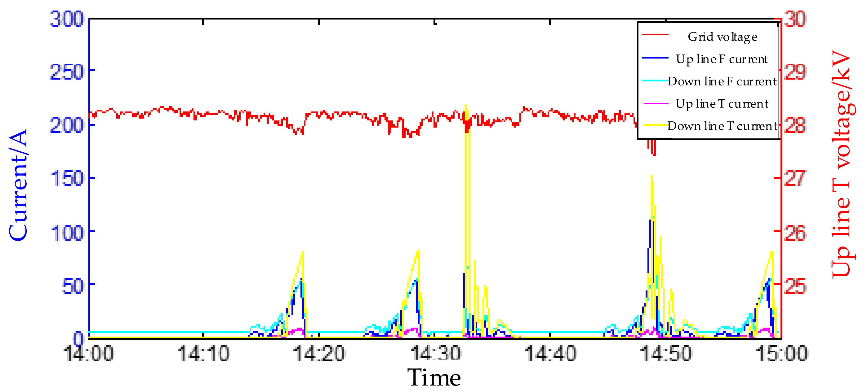
To further improve the reliability of the conclusion, the 27.5 kV railroad section “Hukun 2” of different voltage levels and the 10 kV railroad section “Nankun 1” of different regions were introduced as a comparison. The grounding current and induced voltage at the ungrounded end of the feeder cable of “Hukun 2” are shown in Figure 13, and the output current and voltage of the substation in this section are shown in Figure 14.
Comparing Figure 13 and Figure 14, it can be seen that the grounding current at the shield and armor layer grounding end of the 27.5 kV feeder cable is basically not affected by the feeder cable current, and its value is about 0.5–0.6 A. The induced voltage at the nongrounding end is mainly affected by the cable current and changes with the load, and its value can be about 7 V when the cable current is higher.
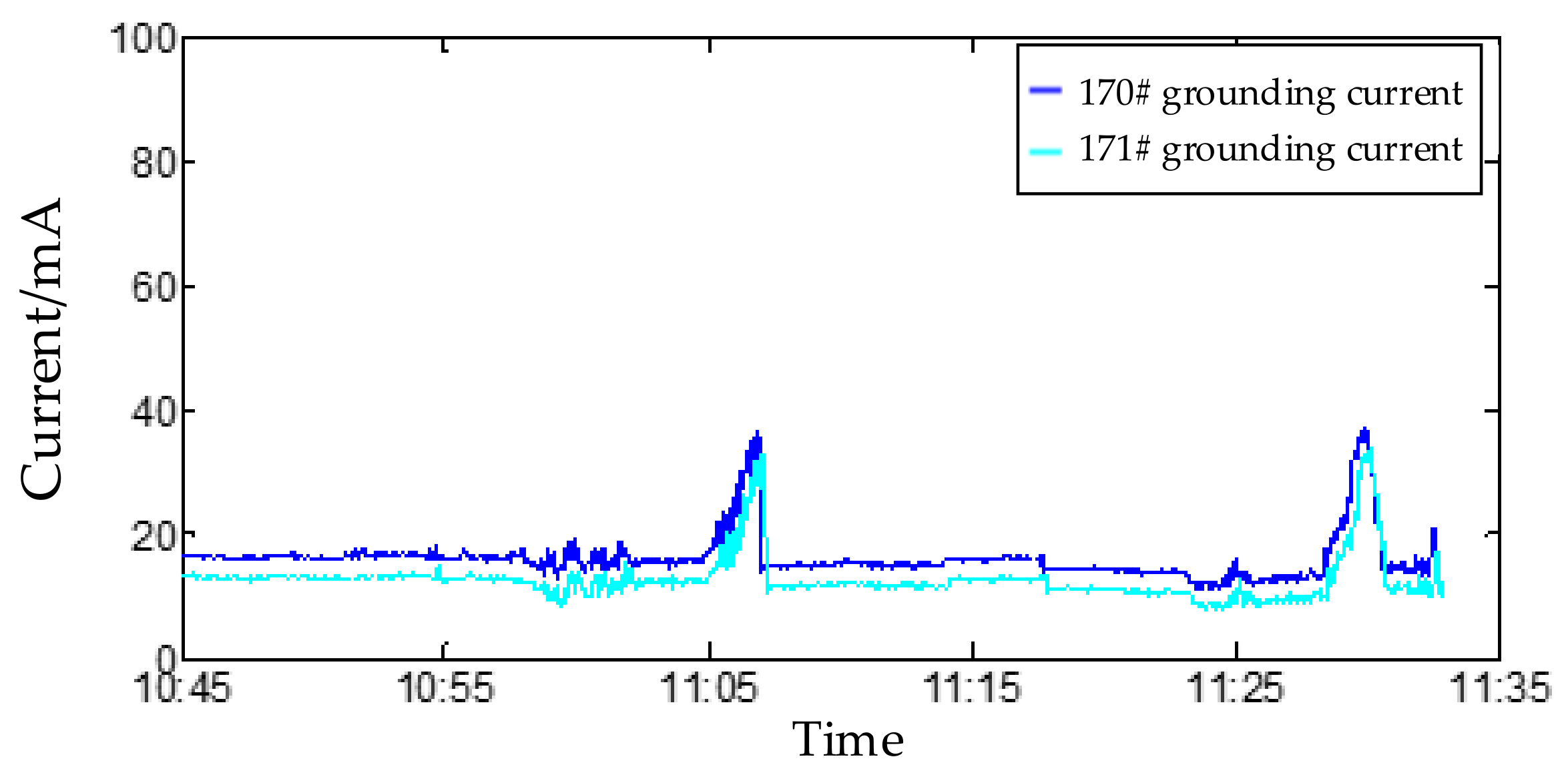
“Nankun 1” 10 kV through line in 170# pole and 171# pole between the cable line, is directly buried in the ground; the cable is a three-core cable at 170# and 171# cable metal sheath using direct grounding, two grounding terminal grounding current as shown in Figure 15. “Nankun 1” traction substation in the test time of each electrical quantity as shown in Figure 16.
From Figure 15 and Figure 16, it can be seen that the sheath loop current after grounding the metal sheath of the “Nankun 1” cable is mainly influenced by the traction power supply system current. When there is a locomotive load traveling through this section of cable, the sheath loop current increases significantly. The loop current is about 15 mA when there is no locomotive load, and the current can increase to 40 mA when there is a locomotive load.
From the measured data, it can be seen that the shield loop current is mainly affected by the core current, and the overall amplitude is less than 1% of the load current and does not affect the operation of the power through line, while a total of equipment protection grounding and normal working conditions through the cable sheath induction voltage is also within 20 V safety voltage, to meet the safety requirements.

4.3. Simulation and Experimental Comparison Analysis

A comparison of the simulated sheath circulating current at 11.4 A and the actual measured circulating current in the “Hukun 1” section is shown in Figure 17.
It can be seen that when the cable core current is 11.4 A, the measured value of the sheath circulating current is 68.7 mA, and the simulated value is 75 mA; the error is less than 10%, which verifies the validity and correctness of the proposed model.
Although the induced voltage is low under normal working conditions measured in the actual test, considering the simulation results for the large load condition of four trains passing through, it can be inferred that the induced voltage of the single-core cable sheath of the through line is very likely to exceed 50 V safety voltage under large load conditions, which is hazardous.

5. Conclusions

Based on the theory of induced potential, this paper analyzes the induced potential and circulating current problem between shield and armor layer of a high-speed railroad power through line and gives a simplified method for an engineering application. Then, relying on CDEGS simulation software, based on single-core cable structure, road-based traction network, and cable location structure, the simulation model of induced potential and the circulating current of a single-core cable sheath of a railroad through line are established, and the simulation of the induced potential and circulating current of the cable sheath under no-load, light-load and heavy-load conditions is carried out for the common equipment protection grounding mode and subequipment protection. Finally, three sections of the Shanghai–Kunming line and the South Kunming line of the Chinese high-speed railroad were selected for field tests, and the test data were compared with the simulation data for analysis.
We concluded that: (1) The traction current has a greater impact on the induced voltage of the metal sheath of the single-core cable; in the absence of the traction current, the induced voltage of the metal sheath of the single-core cable of the power through line is mainly affected by the core current, which is proportional to the core current. With the increase in the traction current, the induced voltage of the metal sheath of the single-core cable of the power through line gradually increases, but is not proportional to the traction current, mainly due to the traction return current through the multiconductor shunt, caused by the asymmetry with the traction current.
(2) Power through line single-core cable outage maintenance: in the cable metal layer there is continuous length control within 3 km, and its nondirectly grounded end of the induced voltage still exists more than 50 V risk and can further reduce the cable metal layer continuous length design requirements.
(3) Power through line single-core cable metal shield layer and armor layer common sheath protector grounding and metal shield layer and armor layer between the ring current: the ring current increases with the increase in the core current, but not more than 1% of the core current, i.e., less than the relevant regulations, so the traction current on the ring current basically does not have an impact.

Author Contributions

Conceptualization, Z.W.; methodology, H.W.; software, H.W.; validation, Z.W.; formal analysis, Z.W.; investigation, H.W.; resources, H.W.; data curation, H.W.; writing—original draft preparation, H.W.; writing—review and editing, H.W.; visualization, H.W.; supervision, Z.W.; project administration, H.W.; funding acquisition, H.W. All authors have read and agreed to the published version of the manuscript.

Funding

This research was funded by China Railway Science and Technology Project, grant number N2021G010.

Institutional Review Board Statement

Not applicable.

Informed Consent Statement

Not applicable.

Data Availability Statement

Not applicable.

Conflicts of Interest

The authors declare no conflict of interest.

References

  1. Liu, G.J. The Study of Principle of Inductive Voltage of Metal Sheathed Single Conductor Cable in High-Speed Railway Power Transmission. Electr. Drive Autom. 2019, 41, 22–25. [Google Scholar]
  2. Chen, S.J. Discussion on Laying and Arrangement of Single Core Cable of Power Transmission Line of High-Speed Railway. Sci. Technol. West China 2011, 10, 18–19. [Google Scholar]
  3. Freschi, F.; Tartaglia, M. Power Lines Made of Many Parallel Single-Core Cables: A Case Study. IEEE Trans. Ind. Appl. 2013, 49, 1744–1750. [Google Scholar] [CrossRef]
  4. Shaban, M.; Salam, M.A.; Ang, S.P.; Sidik, M.A.B.; Buntat, Z.; Voon, W. Assessing Induced Sheath Voltage in Multi-Circuit Cables: Revising the Methodology. In Proceedings of the IEEE Conference on Energy Conversion (CENCON), Johor Bahru, Malaysia, 19–20 October 2015; pp. 272–276. [Google Scholar]
  5. Czapp, S.; Dobrzynski, K.; Klucznik, J.; Lubosny, Z. Computer-aided Analysis of Induced Sheath Voltages in High Voltage Power Cable System. In Proceedings of the 10th International Conference on Digital Technologies, Zilina, Slovakia, 9–11 July 2014; pp. 43–49. [Google Scholar]
  6. Asif, M.; Lee, H.Y.; Park, K.H.; Lee, B.W. Accurate Evaluation of Steady-State Sheath Voltage and Current in HVDC Cable Using Electromagnetic Transient Simulation. Energies 2019, 12, 4161. [Google Scholar] [CrossRef] [Green Version]
  7. Guo, F.S.; Liu, B.; Ji, X.Q.; Zhang, J.; Tao, Z.H.; Lv, Z.Y.; Zhou, W.H.; Wang, Y.Q.; Luan, X.M. Suppression Measures for Overvoltage of SingleCore Cable Sheath Caused by Harmonics and Inrush Current. In Proceedings of the 3rd IEEE Student Conference on Electrical Machines and Systems (SCEMS), Jinan, China, 4–6 December 2020; pp. 636–640. [Google Scholar]
  8. Shaban, M.; Salam, M.A.; Ang, S.P.; Voon, W. Induced sheath voltage in power cables: A review. Renew. Sustain. Energy Rev. 2016, 62, 1236–1251. [Google Scholar] [CrossRef]
  9. Candela, R.; Gattuso, A.; Mitolo, M.; Sanseverino, E.R.; Zizzo, G. A Model for Assessing the Magnitude and Distribution of Sheath Currents in Medium and High-Voltage Cable Lines. IEEE Trans. Ind. Appl. 2020, 56, 6250–6257. [Google Scholar] [CrossRef]
  10. Shen, B.; Lu, T.; Wang, J.; Liu, Z. Influencing Factors of the Induced Voltage in Signal Cable of Electrified Railway. In Proceedings of the Asia-Pacific Power and Energy Engineering Conference (APPEEC), Wuhan, China, 28–31 March 2009; pp. 3687–3690. [Google Scholar]
  11. Fan, C.L.; Guo, X.X. Study on Induced Voltage of Metal Sheath of Single-core Cable. Electr. Railw. 2020, 31, 86–89+93. [Google Scholar] [CrossRef]
  12. Liu, K.; Zhang, L.P.; Wen, X.F. Research on Calculation Model of Induced Voltage and Circulaing Current in Metallic Sheaths of Multiloop Single-core Cable Laying in the Same Cable Channel. Sichuan Electr. Power Technol. 2016, 39, 23–25+72. [Google Scholar] [CrossRef]
  13. Zhao, X. Study on Characteristics of Railway Continuous Power Lines’ Induction Electricity Produced by Electrified Railway. Master’s Thesis, Southwest Jiaotong University, Chengdu, China, 2018. [Google Scholar]
  14. Lo, W.K.; Wong, P.; Leung, S.W.; Siu, Y.M.; Sun, W.N. Analysis of Induced Voltage at Close Proximity with High Voltage Cables of Electrified Railways. In Proceedings of the Joint 60th IEEE International Symposium on Electromagnetic Compatibility (EMC)/IEEE Asia-Pacific Symposium on Electromagnetic Compatibility (APEMC), Singapore, 14–18 May 2018; pp. 944–947. [Google Scholar]
  15. Peng, T.; Chen, J.Y. Simulation of AT Traction Power Supply System for Power Cable Induced Voltage. J. East China Jiaotong Univ. 2017, 34, 113–119. [Google Scholar] [CrossRef]
  16. Hao, J.L.; Du, X.H. Calculation of High Voltage Cable Metal Sheath Induction Voltage Circulation. Mod. Ind. Econ. Inf. 2014, 4, 53–56. [Google Scholar] [CrossRef]
  17. Czapp, S.; Dobrzynski, K. Safety Issues Referred to Induced Sheath Voltages in High-Voltage Power Cables-Case Study. Appl. Sci. 2020, 10, 6706. [Google Scholar] [CrossRef]
  18. Zhang, Z.Y.; Rui, H.R.; Liu, H.C.; Liu, Y.P. Inducted Voltage Simulation of Metal Sheath and Analysis on Maximum Allowable Laying Length for High Voltage Single-core Cable. High Volt. Appar. 2020, 56, 143–148. [Google Scholar] [CrossRef]
  19. Cheng, J. Research on The Sheath Induced Voltage and Grounding Mode of The 27.5kVkV Feeder Cable in High-speed Railway. Master’s Thesis, Southwest Jiaotong University, Chengdu, China, 2016. [Google Scholar]
  20. Mo, Y.-l.; Yuan, X.-h.; Xu, Y.-t.; Dong, G.-t.; Destech Publications, I. Analysis and Calculation of Circulating Current in Grounding for Power Cables. In Proceedings of the International Conference on Material Science and Civil Engineering (MSCE), Guilin, China, 5–7 August 2016; pp. 559–567. [Google Scholar]
  21. Wang, R.L.; Wang, H.M.; Zong, H.B.; Liu, Y.; Sun, J.S. Analysis of Suppression Method for Grounding Circular Current in Metal Sheath of High-voltage Cable. Proc. CSU-EPSA 2019, 31, 108–114. [Google Scholar] [CrossRef]
  22. Ledari, S.A.; Mirzaie, M. Sheath induced voltage prediction of high voltage cable based on artificial neural network. Comput. Electr. Eng. 2020, 87, 106788. [Google Scholar] [CrossRef]
  23. Ma, H.; Song, J.; Ni, X.; Zhang, L. Analysis of induced voltage in metal shield of power cable and research on its restraining technology based on asymmetric state. In Proceedings of the 3rd International Conference on Electric Utility Deregulation, Restructuring and Power Technologies, Nanjing, China, 6–9 April 2008; pp. 948–951. [Google Scholar]
  24. Tan, D.; Bai, H.; Sun, K.; Wang, Z. Research on On-line Monitoring Device of Circulation in High Voltage Cable Metal Sheath. In Proceedings of the International Symposium on Material, Energy and Environment Engineering (ISM3E), Changsha, China, 28–29 November 2016; pp. 267–269. [Google Scholar]
  25. Santos, M.; Angel Calafat, M. Dynamic simulation of induced voltages in high voltage cable sheaths: Steady state approach. Int. J. Electr. Power Energy Syst. 2019, 105, 1–16. [Google Scholar] [CrossRef]
  26. Czapp, S.; Dobrzynski, K.; Klucznik, J.; Lubosny, Z. Impact of Configuration of Earth Continuity Conductor on Induced Sheath Voltages in Power Cables. In Proceedings of the International Conference on Information and Digital Technologies (IDT), Rzeszow, Poland, 5–7 July 2016; pp. 59–63. [Google Scholar]
  27. Xia, R.; Luo, J.H.; Li, W.J.; Chen, L.R. Study on On-Line Detection and Suppression of Induced Voltage and Circulating Current in Metal Sheath of Large Section and Long-distance 35 kVkV Single Core Cross-Linked Cable. In Proceedings of the 2011 International Conference on Software Engineering and Multimedia Communication (SEMC), Shenzhen, China, 9 July 2011; pp. 520–524. [Google Scholar]
  28. Schott-Szymczak, A.; Walczak, K. Impact of Cable Configuration on the Voltage Induced in Cable Screen during Work with One-Sidedly Ungrounded Cable Screen. Energies 2021, 14, 4263. [Google Scholar] [CrossRef]
Figure 1. The distance between each phase cable core of a single-core cable.
Energies 15 05010 g001
Figure 2. Schematic diagram of the distance between multiple conductors and the core of each phase of a single-core cable.
Energies 15 05010 g002
Figure 3. Traction network and cable location in subgrade.
Energies 15 05010 g003
Figure 4. CDEGS traction power supply system model.
Energies 15 05010 g004
Figure 5. Single-core cable structure.
Energies 15 05010 g005
Figure 6. PQM16-D traction substation power quality monitoring system.
Energies 15 05010 g006
Figure 7. “Hukun 1” 10 kV feeder cable single-end grounding test structure.
Energies 15 05010 g007
Figure 8. “Hukun 2” 27.5 kV feeder cable double-end grounding test structure.
Energies 15 05010 g008
Figure 9. “Nankun 1” 10 kV feeder cable double-end grounding test structure.
Energies 15 05010 g009
Figure 10. “Hukun 1” 10 kV cable power transmission line through the cable core current.
Energies 15 05010 g010
Figure 11. “Hukun 1” induced voltage at the ungrounded end of the cable sheath.
Energies 15 05010 g011
Figure 12. “Hukun 1” circulating current of cable sheath at the ungrounded end.
Energies 15 05010 g012
Figure 13. The grounding current and induced voltage at the ungrounded end of the feeder cable of “Hukun 2”.
Energies 15 05010 g013
Figure 14. Ground currents and induced voltages at the substation of “Hukun 2”.
Energies 15 05010 g014
Figure 15. “Nankun 1” 10 kV through line 170#, 171# cable metal sheath grounding current.
Energies 15 05010 g015
Figure 16. “Nankun 1” traction substation in the test time of each electrical quantity.
Energies 15 05010 g016
Figure 17. Comparison of simulated circulating current and actual measured value for 11.4 A model of wire core current.
Energies 15 05010 g017
Table 1. Induced voltage of shield layer and armor layer under different core currents.
Core Current/A20406080100
Induced voltage of shield layer/V3.6067.21310.81914.42618.032
Induced voltage of armor layer/V3.2576.5149.77013.02716.284
Table 2. AT power supply system parameters of each conductor.
Conductor TypeResistance (20 °C)/(Ω/km)Nominal Cross Area/mm2Calculate Cross Area/mm2
Contact wire (CTMH-150)0.1852150151
Carrier cables (JTMH-120)0.242120116.99
AF lines (LGJ-300/50)0.09636Aluminum 300/steel 50Aluminum 299.54/steel 48.82
PW lines (LGJ-120/20)0.2496Aluminum 120/steel 20Aluminum 115.67.54/steel 18.82
Grounding wire (TJ-95)0.209593.27
Table 3. Single-core cable model parameters.
Cable Specification1 × 95 mm2
Cable CoreSheathArmor
Conductor DefinitionInner Radius (mm)011.412.54
Outer Radius (mm)5.511.6412.74
Relative Resistivity111.6
Insulation definitionThickness (mm)5.90.92
Resistivity (Ω·m)101410141014
Relative Permittivity111
Table 4. Simulation value of induced voltage of metal sheath with a separate sheath protector when there is no vehicle.
PhaseABCABC
Core Current/AVoltage of Cable Armor Layer/VVoltage of Cable Shield Layer/V
00.0580.0590.0580.0580.0590.058
203.203.483.114.474.764.39
406.436.906.248.058.537.86
609.6610.329.3711.6312.2911.34
8012.8913.7412.5015.2116.0614.82
10016.1217.1615.6318.7919.8318.30
Table 5. Simulation value of induced voltage and calculating current of metal sheath with a common sheath protector when there is no vehicle.
PhasePhase APhase BPhase C
Core Current/AVoltage/VCurrent/AVoltage/VCurrent/AVoltage/VCurrent/A
00.0585.78 × 10−60.0595.79 × 10−60.0585.68 × 10−6
204.010.1564.290.1553.920.156
407.460.1987.930.1997.270.199
6010.910.24111.580.24110.630.241
8014.370.28415.220.28413.980.284
10017.820.32618.860.32617.330.326
Table 6. Simulation value of induced voltage of metal sheath with a separate sheath protector when there is a single vehicle.
PhaseABCABC
Core Current/AVoltage of Cable Armor Layer/VVoltage of Cable Shield Layer/V
053.3353.6752.7453.3353.6752.74
2055.7150.4953.3556.5149.5653.60
4058.2147.3554.0659.3146.1254.47
6060.7744.2654.9462.1942.7355.55
8063.4041.2255.9865.1539.4156.82
10066.0738.2457.1868.1636.1958.27
Table 7. Simulation value of induced voltage and calculating current of metal sheath with a common sheath protector when there is a single vehicle.
PhasePhase APhase BPhase C
Core Current/AVoltage/VCurrent/AVoltage/VCurrent/AVoltage/VCurrent/A
053.554.43 × 10−353.674.45 × 10−352.744.38 × 10−3
2056.220.12549.900.16653.510.118
4058.910.16746.570.12354.320.161
6061.680.21043.290.20855.320.204
8064.510.25240.070.25156.510.246
10067.400.29536.930.29357.860.289
Table 8. Simulation value of induced voltage of metal sheath with a separate sheath protector when there are four vehicles.
PhaseABCABC
Core Current/AVoltage of Cable Armor Layer/VVoltage of Cable Shield Layer/V
0120.42121.40119.16120.44121.41119.18
20122.58118.12120.03123.51116.90120.43
40124.80114.85120.88126.01113.30121.43
60127.07111.58121.81128.56109.71122.51
80129.38108.33122.81131.15106.12123.69
100131.72105.08123.88133.80102.56124.95
Table 9. Simulation value of induced voltage and calculating current of metal sheath with a common sheath protector when there are four vehicles.
PhasePhase APhase BPhase C
Core Current/AVoltage/VCurrent/AVoltage/VCurrent/AVoltage/VCurrent/A
0120.4438.7 × 10−3121.418.76 × 10−3119.178.61 × 10−3
20123.170.161117.350.15612.280.151
40125.570.204113.860.199121.220.193
60128.010.247110.390.241122.250.236
80130.510.289106.930.284123.360.278
100133.040.332103.480.326124.550.321
Publisher’s Note: MDPI stays neutral with regard to jurisdictional claims in published maps and institutional affiliations.

