Abstract
The paper is a continuation of the research works of the authors. The aim of it is identifying the electromagnetic environment in which the control equipment of the short-circuit test stand operates. Exceptional attention was devoted to the issues related to the operation of the time-phase controller system. Measurements and identification of the electromagnetic environment were carried out on a specific short-circuit test stand, where short-circuit currents are generated by the medium-voltage (MV) short-circuit transformers. Short circuit tests are always preceded by powering the MV side of the test transformer by unloading the low-voltage (LV) side. Thereafter, the controller must wait for the release of the operator to start the test. Sometimes an electromagnetically disturbed controller starts the test without release. Such situation is undesired and can be destructive for the tested objects. Identification of the transient fields during the powering of the test transformer is indispensable for assessing the hazard of EM interference of the controller. Earlier research by the authors showed that the repetitive damped oscillating waves (DOW) are a component of the electromagnetic environment. Adequate instrumentation to cope with the problem are D-dot and B-dot field probes is needed. The paper reports such measurements along with recording the voltage signals. It was suspected that repetitive ignition and extinction of the short arc by closing the circuit breaker in the MV circuit is the origin of the DOW. Additional investigation of the circuit breaker in stand-alone operation is excluded in this hypothesis. The only possibility of the DOW is pulse traveling back and forth in the MV circuit, which is a line with distributed parameters.
1. Introduction
In our case, preparation of the short circuit test consists of switching the primary side of the MV/LV transformer to the medium voltage source. It is called powering the test transformer. Then, the set-up is ready to perform DUT tests. Powering of the test transformer was performed with the MV Vacuum Circuit Breaker, the brand name EVOLIS 17.5 kV, product of Merlin Gerin [1], as shown in Figure 1 and, during the test, in Figure 2. The magnetizing current of the transformer can be limited with the current limiting inductors, as shown in Figure 1.
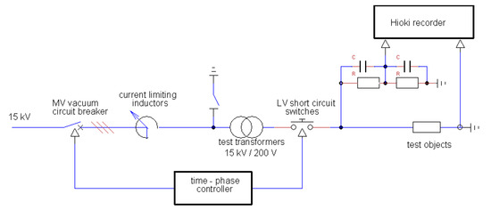
Figure 1.
Electrical scheme illustrating the test circuit.
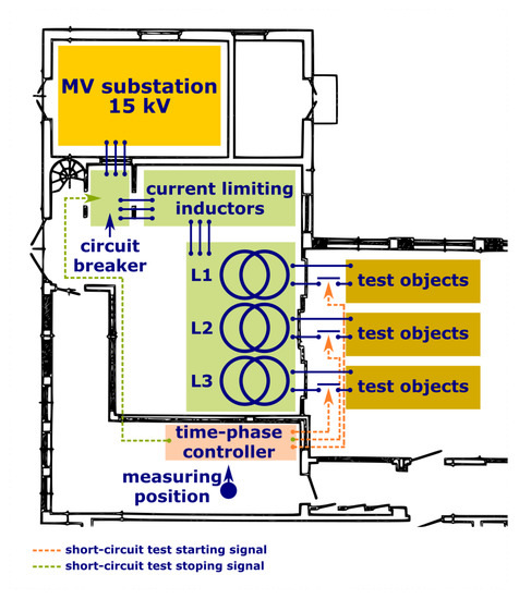
Figure 2.
Situation plane of the high-current laboratory.
From that instant, the time-phase controller is waiting for the release of the operator to start the test. However, sometimes, under some circumstances, the controller starts the test without the operator’s release. Such situation is undesired and can be destructive for the device under test.
The paper is a continuation of the research works of the authors. reported in [2].
The laboratory launched the project of developing the new time phase controller compatible to the environment of dedication. In parallel to the development of the mentioned hardware, the electromagnetic environment of the high current laboratory is identified in order to consciously build hardware that is immune to the required range. This paper reports these investigations. The aim is to establish the scope of immunity tests and severity levels, the passing of which will ensure the operation of the new controller without malfunction.
First of all, the tests described in the standard [3] were requested. Generic standard [3] is dedicated to the environment of power stations, high and medium voltage substations as well as indoor industrial facilities directly connected to the MV power network. This standard is mandatory for electronic equipment applied in the high-current laboratory under consideration.
One of the tests required in the standard [3] is immunity against slow and fast damped oscillatory waves. The generic standard requires testing this immunity according to basic standards in [4].
It is explained in [4] that the slow damped oscillatory waves are particularly related to the switching of disconnectors in HV/MV open-air substations and is particularly related to the switching of HV busbars. The fast damped oscillatory waves are present in substations of the power network, produced by switchgears and controlgears. In that context, air insulated substations (AIS), made up of only air insulated switchgear, and gas insulated substations (GIS), made up of only gas insulated metal enclosed switchgears, are mentioned.
Citation from [4]: “During opening or closing disconnector operations, between both contacts of the operated device, a large number of restrikes take place due to the slow speed of the contacts. Therefore, disconnector switch operations generate very fast transients, which propagate as traveling waves in the busbars of the substation. The electrical length of conductors and busbars will determine the oscillation frequencies of the transient overvoltages”.
The time phase controller itself is placed in the control room, as shown in Figure 2, but the signal and control cables originate either in the medium voltage area, green dashed line in Figure 2, or in the low voltage area, orange dashed lines in Figure 2. Electromagnetic disturbance, most likely manifested there with a transient electric field, can couple with the cables via cross talks and can penetrate the controller causing its malfunctioning.
Identification of the transient fields during the powering of the test transformer is indispensable for assessing the hazard of the EM interference of the time-phase controller.
As the result of the literature research conducted by the authors in the scope of electromagnetic environments in high current laboratories, papers [5,6,7] must be pointed out. The publications [8,9] can be mentioned but they concern only low-frequency magnetic fields.
A rough identification of the electromagnetic phenomena by short circuit tests in the mentioned laboratory is reported in [10]. The adjective “rough” is justified in that context because the first measurements indicated slowly damped oscillatory waves accompanying the closing of the circuit breaker.
The phenomenon of the damped oscillatory wave can extend in the frequency range up to hundreds of MHz. However, the frequency band of the field probe used during the measurements reported in [10] reaches only 400 kHz. It is definitively too low to capture the phenomenon reliable. This reason, as well as the peculiarity of an electromagnetic environment installation with a vacuum insulated breaker, convinces the authors to retake the measurement with adequate field probes, as suggested in the conclusions of [10], and record transients at the signal ports of the time-phase controller.
In order to exclude or confirm the origin of the repetition of the damped oscillatory waves, the circuit breaker was investigated in the stand-alone operation.
2. Repetitive Damped Oscillatory Waves
The scope of the standard [4] encompasses the repetitive damped oscillatory waves occurring mainly in power, control and signal cables installed in high voltage and medium voltage (HV/MV) substations. This phenomenon accompanies switching operations in HV/MV open-air substations. It gives rise to sharp transients, with rising times of the order of some tens of nanoseconds.
The formula of the ideal single damped oscillatory wave, according to [4] is as follows
where is the natural frequency of the excited circuit , () is the attenuation constant and product of n, and is approximately equal to the front time of the first slope of the oscillations ().
In the standard [4], slow damped oscillations with 100 kHz and 1 MHz, as well as fast damped 3 MHz, 10 MHz and 30 MHz oscillations, are defined.
It can be learned from the formula in Equation (1) that the phenomenon is an overlay of the fast transient and the damped oscillations of the serial circuit with a natural frequency of
Parameters corresponding to 1 MHz slow damped oscillations presented in Figure 3 are gathered in Table 1. In the presented case, ns. This corresponds to the bandwidth of the phenomenon MHz. This is eight times bigger than natural frequency .
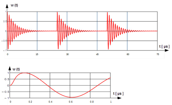
Figure 3.
Example of slow-damped 1 MHz oscillations with 25 µs repetition’s rate [4].

Table 1.
Parameters of the slow damped 1 MHz oscillations.
Repetitive oscillations are generated due to multiple ignition and extinction of the short arc by closing the circuit breaker. The phenomenon is similar to “arc showering” described in [11] or in [12] and modeled numerically in [13]. Repetition rate depends on the electrical parameters of the circuit shown in Figure 1.
3. Measurement of Transient Fields Due to Closing of the MV Circuit Breaker
Electric and magnetic field strengths were measured in the control room by closing the MV circuit breaker. The current limiting inductors were dismounted from the circuit. The transformation ratio was set to 15 kV/0.2 kV. Only one transformer was powered, marked as No. L3 in Figure 2.
The positions of probes are marked in Figure 2. The measurements were performed in three orthogonal orientations of the probes, as in Figure 2, which are named as follows:
- Vertical, see Figure 4,
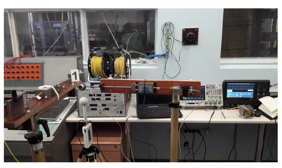 Figure 4. Probes oriented vertically [2].
 - Perpendicular to the wall separating the control room and the medium voltage area, see Figure 5,
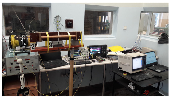 Figure 5. Probes oriented perpendicular to the separation wall [2].
 - Along the wall separating the control room and the medium voltage area, see Figure 6.
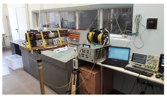 Figure 6. Probes orientated along the separation wall [2].
The measurement setup was built up with:
- free space electric field sensor SFE3-5G with bandwidth from 100 kHz to 3.5 GHz,
- free space magnetic field sensor SFM2G with bandwidth from 100 kHz to 2 GHz,
- Digital oscilloscope WAVESURFER 3074 with 750 MHz analog bandwidth and 4 GS/s sampling rate, product of TELEDYNE LeCroy.
Both probes are products of MONTENA Technology SA. Integration was performed after the measurements with the script written in Matlab.
Low voltage of the transformer and one signal input of the controller were simultaneously recorded, as shown in Figure 2. The transients recorder MEMORY HiCORDER 8861-50 with two channels plugged into ANALOGUE UNIT 8956 were used for these measurements. Both pieces of measurement equipment are products of HIOKI E.E. CORPORATION. HiCORDER 8861-50 has a maximum sampling rate of 20 MS/s. The analog unit also has a sampling rate of 20 MS/s when sampling simultaneously in two channels.
The time-dependent diagrams captured with field probes are presented in Figure 7, Figure 8, Figure 9, Figure 10, Figure 11 and Figure 12. The time-dependent diagrams captured with the HiCORDER 8861-50 are presented in Figure 13, Figure 14 and Figure 15. The important parameters of the recorded signals are gathered in Table 2 and Table 3.
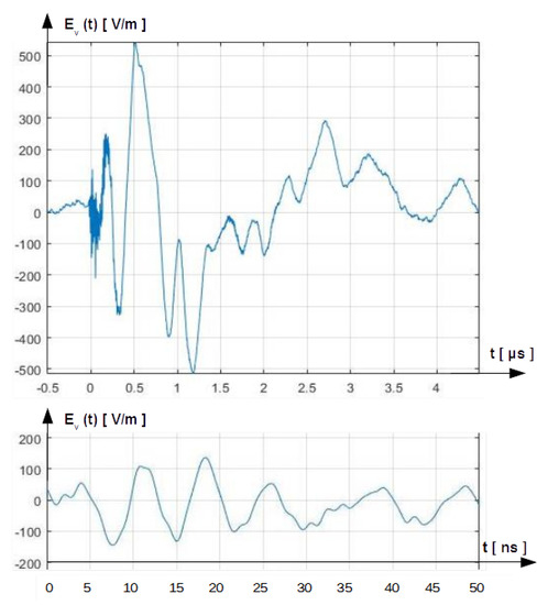
Figure 7.
Vertical component of the E-field [2].
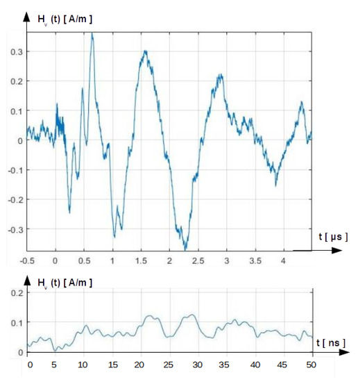
Figure 8.
Vertical component of the H-field [2].
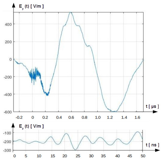
Figure 9.
Component of the E-field perpendicular to the separation wall [2].
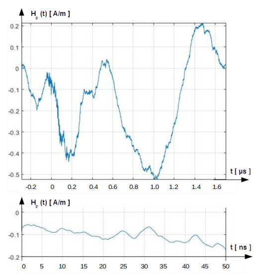
Figure 10.
Component of the H-field perpendicular to the separation wall [2].
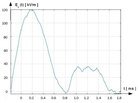
Figure 11.
Component of the E-field along the separation wall [2].
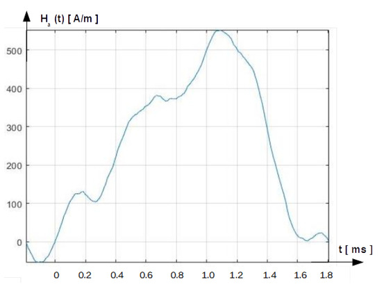
Figure 12.
Component of the H-field along the separation wall [2].
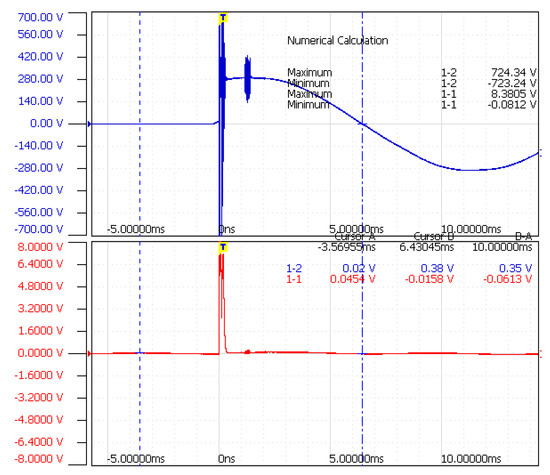
Figure 13.
Signals recorded with HiOKI 8861-50 during measurement of the vertical field component.
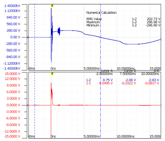
Figure 14.
Signals recorded with HiOKI 8861-50 during measurement of the field component perpendicular to the separation wall.
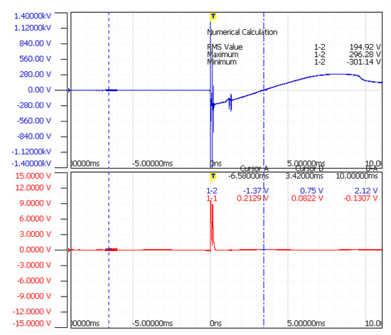
Figure 15.
Signals recorded with the HiOKI 8861-50 during the measurement of the field component along the separation wall.
Table 2.
Voltage parameters captured with the HiCORDER 8861-50.
Table 3.
Time parameters measured with the HiCORDER 8861-50.
4. MV Circuit Breaker Tests in Stand-Alone Operation
For confirmation or exclusion that the repetitive damped oscillatory waves are due to the closing of the contacts of the circuit breaker, the MV Circuit Breaker was dismounted from the MV circuit and connected, as shown in Figure 16. The tests were made with two types of electromotive forces EMF:
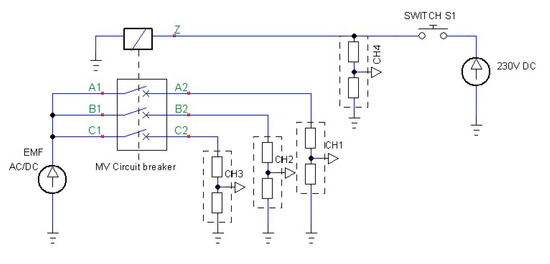
Figure 16.
Circuitry by investigation of the MV circuit breaker in stand-alone operation.
- 9 V DC,
- 15 kV, 50 Hz.
For the measurements in the first case, four low-voltage test probes Teledyne LeCroy PP022 with 500MHz bandwidth, 600 V range and 10:1 division were applied, see Figure 17. The measurement results are presented in Figure 18.
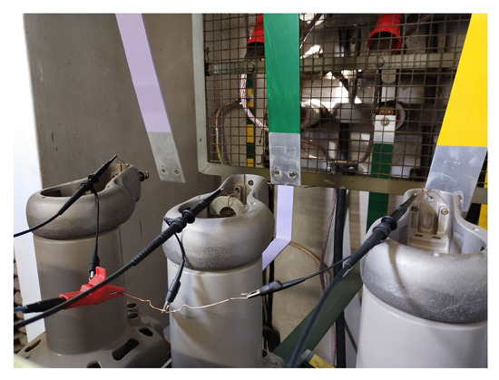
Figure 17.
The set-up for the MV circuit breaker stand-alone operation with low voltage DC EMF.
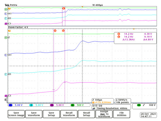
Figure 18.
Oscilloscope diagrams of the four channels by closing the contacts of the MV circuit breaker supplied with low-voltage DC EMF.
In the second case, four high-voltage probes P6015A—Tektronix—with 75 MHz bandwidth, 20 kV voltage range and 1000:1 division factor were used, see Figure 19.
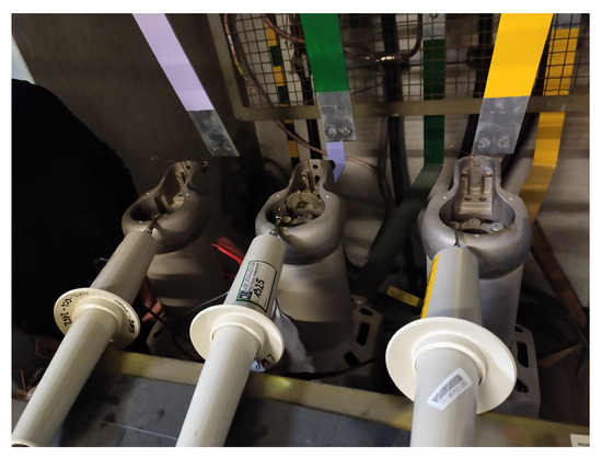
Figure 19.
The set-up for the MV circuit breaker stand-alone operation with MV AC EMF.
In both cases the four channels oscilloscope MSO 4054 Tektronix was used.
The damped oscillation by stand-alone operation are not observed neither by LV DC nor by MV AC supply, see Figure 18 and Figure 20.
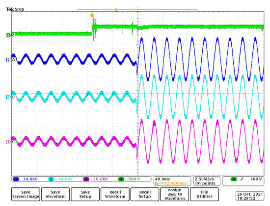
Figure 20.
Oscilloscope diagrams of the four channels by closing the contacts of the MV circuit breaker supplied with MV AC EMF.
The contacts in each phase do not close in the same instant, see Figure 18. It generates a common mode component of the field.
5. Conclusions
Some of the conclusions were presented in [2]. For the sake of completeness, they are repeated here.
It must be emphasized that measured field components do not concern the same event because the and probes are directional. The intensity of the transient phenomenon depends on how the instant of switching the MV circuit breaker is referred to the 0-crossing of the 50 Hz medium voltage source. This can be random from event to event.
The complexity of the phenomenon that accompanied the closing of the circuit breaker is overwhelming damped oscillatory waves, as defined in [4]. They are distorted. Therefore, their bandwidth is much bigger than the standardized DOW.
Components of the electric field vertical and perpendicular to the separation wall reach several hundreds of V/m, which unambiguously extends levels allowed in the industrial environment, see Figure 7 and Figure 9. Corresponding magnetic field components reach merely several A/m, which is harmless even in a domestic environment, see Figure 8 and Figure 10.
The component of the electric field along the separation wall is slowly varying in time but is extremely high, see Figure 11. It extends 100 kV/m. The magnetic field is also slowly varying in time and has a high peak value, reaching several hundreds of A/m, see Figure 12.
The new conclusions from this paper are described below.
Experiments with the operation of the circuit breaker alone provided the answer that the repetitive damped oscillatory waves are not due to closing the contacts of the circuit breaker. The origin of it is rather a distributed line of the MV circuit along which the pulse is traveling and reflects at the transformer due to mismatching. This conclusion is in accordance with that presented in [14].
The fact that the contacts do not close in the same instant, as observed by the stand-alone tests of the MV circuit breaker, can be another reason for repetitive oscillations.
Author Contributions
Conceptualization, J.S. (Jan Sroka); Formal analysis, M.O.; Methodology, P.S.; Project administration, J.S. (Jolanta Sadura); Validation, A.J. All authors have read and agreed to the published version of the manuscript.
Funding
This research received no external funding.
Institutional Review Board Statement
Not applicable.
Informed Consent Statement
Not applicable.
Data Availability Statement
Not applicable.
Conflicts of Interest
The authors declare no conflict of interest.
References
- KATKT10008. Vacuum Circuit Breaker Evolis 24 kV. 2004. Available online: http://www.schneider-electric.pl (accessed on 20 March 2022).
- Sadura, J.; Sroka, J.; Owsiński, M.; Jóśko, A. Identification of EM disturbances interfering the time-phase controller by short circuit tests. In Proceedings of the 2020 International Symposium on Electromagnetic Compatibility—EMC EUROPE, Rome, Italy, 23–25 September 2020. [Google Scholar]
- IEC 61000-6-5; Electromagnetic Compatibility (EMC)—Part 6–5: Generic Standards—Immunity for Equipment Used in Power Station and Substation Environments. IEC: Geneva, Switzerland, 2015.
- IEC 61000-4-18; Electromagnetic Compatibility (EMC)—Part 4–18: Testing and Measurement Techniques—Damped Oscillatory Wave Immunity Test. IEC: Geneva, Switzerland, 2019.
- Burger, D.; Tenbohlen, S.; Köhler, W.; Ebbinghaus, W. Sources of transient electromagnetic disturbance in medim voltage switchgear. In Proceedings of the 10th International Symposium on Electromagnetic Compatibility, York, UK, 26–30 September 2011; pp. 597–602. [Google Scholar]
- WG C4.208; EMC within Power Plants and Substations. CIGRE: Paris, France, 2013; ISBN 978-2-85873-229-6.
- Imposimato, C.; Hoeffelman, J.; Eriksson, A.; Siew, W.; Pretorius, P.; Wong, P. EMI Characterization of HVAC Substations—Updated data and Influence on Immunity Assessment; CIGRE: Paris, France, 2002; pp. 36–108. [Google Scholar]
- Cangemi, G.; Cataliotti, A.; Cipriani, G.; Di Dio, V.; Nucio, S.; Di Cara, D.; Tin, G.; Melodia, M. Experimental EMF Characterization of a Secondary Substation. In Proceedings of the AEIT Annual Conference, Naples, Italy, 14–16 October 2015. [Google Scholar]
- Meng, Y.; Zhang, B.; Shen, W.; Wang, S.; Ma, Y. Overvoltage of secondary cables in substation due to short circuit fault. In Proceedings of the Electromagnetic Compatibility and 2018 IEEE Asia-Pacific Symposium on Electromagnetic Compatibility (EMC/APEMC), Singapore, 14–18 May 2018; pp. 1099–1102. [Google Scholar]
- Sadura, J.; Sroka, J.; Owsiński, M. Rough identification of EM disturbances interfering the time-phase controller by the short circuit tests. In Proceedings of the 12th International Conference on Electrical Power Quality and Utilisation (EPQU’20), Kraków, Poland, 14–15 September 2020. [Google Scholar]
- Ott, H.W. Noise Reduction Techniques in Electronic Systems; John Willey & Sons: Hoboken, NJ, USA, 1988. [Google Scholar]
- Paul, C.R. Introduction to Electromagnetic Compatibility; John Wiley & Sons, Inc.: Hoboken, NJ, USA, 1992. [Google Scholar]
- Starzyński, J.; Sroka, J. Improved Simulation Model of Electrical Breakdown in Air. In Proceedings of the 2019 IEEE 20th International Conference on Computational Problems of Electrical Engineering (CPEE), Lviv-Slavske, Ukraine, 15–18 September 2019; pp. 1–4. [Google Scholar]
- Kawamata, K.; Minegishi, S.; Haga, A.; Sato, R. Measurement Method Using Coupled Transmission Lines for Voltage Transients on the Distribution Line. Electr. Eng. Jpn. 1995, 115, 563–567. [Google Scholar] [CrossRef]
Publisher’s Note: MDPI stays neutral with regard to jurisdictional claims in published maps and institutional affiliations. |
© 2022 by the authors. Licensee MDPI, Basel, Switzerland. This article is an open access article distributed under the terms and conditions of the Creative Commons Attribution (CC BY) license (https://creativecommons.org/licenses/by/4.0/).