1. Introduction
Intensive development of power electronic devices in recent decades has resulted in significant changes in the methods of supplying power to electric drives, hence improving the energy efficiency of the drives and obtaining much better dynamic properties. The main element of this revolution was inverter systems, in which control consists of the permanent switching of transistors. As a consequence, an almost rectangular shape of the voltages supplying the motor is achieved. In the case of systems with low power and low voltages, it is possible to use relatively high switching frequencies, which, combined with the inductive nature of electric machines, allows for almost perfect shaping of the current, and thus the torque produced by the motor.
One of the most important phenomena occurring in motor drives is the possibility of mechanical resonance [
1,
2,
3,
4,
5]. In popular systems adapted to low power drives, the so-called “frequency bypass” is used. This is a typical function of any industrial inverter. This enables the elimination of the first voltage harmonic, which is most responsible for the mechanical resonance.
In the case of high-power systems, for whom the switching frequency is very close to the first harmonic frequency, there may be a resonant interaction of the mechanical system with frequencies arising as a result of voltage modulation. This is particularly important in the case of mechanical transmission systems with elastic shafts and in systems with turbines [
2,
3]. For variable speed drive systems where the first harmonic varies from 0 to the maximum frequency, the higher harmonics produced also have a variable frequency. In this situation, the elimination of the selected harmonics does not allow the avoidance of resonance.
In case of high-power devices, it is increasingly more difficult to obtain a sufficiently high frequency of switching. This is mainly due to losses in transistors, which are dependent on parameters that are extremely harmful for high voltage switches. Another problem in the case of devices designed to work at voltages exceeding the values of several kV is the lack of appropriate transistors. One of the solutions to overcome this problem is the use of inverters with multi-level structures. In this case, there are two simultaneous advantages: it is possible to use transistors with blocking voltages that are lower than the supply voltage, and the number of commutations per transistor can be reduced, i.e., losses can be reduced.
In the case of drives with power exceeding 1 MW, which require voltages from 4 to 15 kV to feed power supply, even the use of multi-level structures forces the limitation of the switching frequency to very low values; in the extreme case, the minimum number of switches shapes the first harmonic voltage of the motor supply voltage (Sixstep) [
6]. This is associated with a very unfavorable formation of the current and torque produced in the motor. There are many works on this subject [
7,
8,
9,
10,
11]. The authors usually focus on specific harmonics in which they identify certain types of problems.
The paper [
12] presents the mechanism of torque harmonics formation in drives powered from transistor inverters. It is noted here that the n
th harmonic of the torque is formed from the n
th − 1 and n
th + 1 harmonic supply voltages of the motor. In [
2], the influence of modulation methods on the torque frequency response, for low-switching frequencies in a three-level inverter, is analyzed. The method of optimal calculation of switching angles is presented. The optimization criterion indicated the minimization of RMS values of 6, 12, 18, etc., torque harmonics. The presented method was compared with the SHE and STPWM methods using simulation research and experiments.
The article [
13] proposes the optimal selection of the carrier signal frequency for a three-level voltage inverter (NPC). The optimization criterion was chosen to meet the criteria of three-phase symmetry (TPS) and half-wave symmetry (HWS).
The authors of the paper [
14] considered the possibility of limiting the spectrum of torque oscillations by using a hybrid SVPWM technique for a two-level inverter. The presented solutions allow for a significant reduction in the peak-to-peak value of undesirable torque components for high motor speeds.
The works [
15,
16,
17,
18] were devoted to the optimization of harmonics in the DC-link circuit current and phase current harmonics for two- or three-level voltage inverters supplying traction drives. In this work, the selective harmonic elimination and mitigation (SHEAM) method was proposed.
Additionally, the work [
19] discusses the SHE method in the context of a three-level voltage inverter.
In the article [
20], a new method of direct torque control (DTC) for multi-level voltage inverters was proposed. The authors discussed torque harmonics’ spectrum formation. The results of simulation and experimental research carried out for a three-level NPC inverter were also presented.
Paper [
11] presents a new method of synchronized space-vector pulse width modulation (SSVPWM) for a three-level NPC inverter, meeting the symmetry of TPS, HWS, QWS while limiting the switching of only two transistors in one sampling period. The presented control scheme was compared experimentally and using simulation with CSSPWM and SDPWM.
In the papers [
21,
22,
23], various carrier-based PWM control strategies focusing on minimizing selected harmonics of torque for the induction motor powered from two- and three-level inverters were presented.
Most of the presented works deal with the analysis, reduction, or elimination of selected harmonics in order to reduce losses or improve the quality of operation for the devices.
This article presents the concept of using the method of selective torque component elimination in order to achieve the full range of speed control with minimization of the specific selected frequency of mechanical pulsations.
2. Methodology
The methodology used for the study presented in this article was based on the use of the simulation model of an induction motor (0.4 kV DC–2.2 kW) verified in the laboratory stand with the same parameters. Only steady states were taken under consideration, and the Fast Fourier Transform (FFT) algorithm was used to determine current, voltage, and toque harmonics amplitudes.
2.1. Torque Harmonics Formation in Inverter Powered Drive Systems
The electromagnetic torque in the motor is produced by the interaction of the rotor and stator fluxes. The basic expression determining its value is given by the formula:
where: p—number of pole pairs, L
m—mutual inductance, L
s—inductance of stator windings, L
r—inductance of rotor windings, ψ
s—flux associated with stator, ψ
r—flux associated with rotor, and all values are instantaneous. The values of stator and rotor fluxes are functions of the stator voltage. The relationship between voltage and fluxes is given by the following formula:
Due to the way the motors are powered by inverters, the voltage supplied to the terminals has a rectangular shape. Due to the design of the motors related to their three-phase character and symmetry, the resulting torque contains pulsations with frequencies that are six times the frequency of the first harmonic voltage [
12]. The values of each of these harmonics are determined by the harmonics of the currents and fluxes:
where: τ
n—RMS value of the n
th harmonic of torque; ψ
m1, ψ
m(n-1), ψ
m(n+1) are respectively the fundamental harmonic of the flux and its n
th + 1, n
th − 1 harmonics; I
r1, I
r(n − 1), I
r(n + 1) are respectively the values of the fundamental harmonic of the rotor current and its n
th + 1, n
th − 1 harmonics.
The harmonics of the flux and current are formed as a result of the stator voltage. However, the relationships between these quantities are not easy to determine analytically. It is only possible to find approximate formulas showing the main components of the harmonics of voltages affecting fluxes and currents:
As a result, the following relationship can be written:
where a and b are the corresponding constants.
The relationship shows that, in order to eliminate the nth torque harmonic, it is necessary to lead to a situation in which the amplitudes of nth + 1 and nth − 1 harmonics of the phase voltage supplying the motor are equal but opposite in sign. Usually, the authors of the works determine the quality indicator on the basis of the above formulas, and on its basis look for an analytical relationship that allows the switching angles to be obtained.
Unfortunately, the analytical attempts to find the relationship between the harmonics of voltage and torque each time require significant simplifications, which reduce their effectiveness. The methods presented in [
1,
4,
12,
22,
24] lead to the operation on specific harmonics of stator voltages in order to produce or eliminate specific harmonics of the driving torque. Unfortunately, their use is limited, among other things, by the number of harmonics that can be eliminated, depending on the number of switching angles per quarter.
A reliable approach to determining the relationship between the inverter output voltage and torque requires solving complex differential equations. Even this way of solving the problem is not perfect, because the quality of elimination of selected harmonics in the real device is also influenced by hardware limitations such as deadtimes and minimal pulses, especially in high-power inverters. Another major limitation of analytical methods is the power supply status of the motor with modulation coefficients exceeding 1. Therefore, the authors of the current paper developed an algorithm for determining the switching angles of the inverter for all possible amplitude states and frequencies of the first harmonic voltage. The assumption of the algorithm is a simulation solution to the problem of optimizing the harmonics of the torque by finding the best system of switching angles that implements the given operating state. This solution requires a huge number of numerical calculations at the stage of preparation of switching angle tables. The result of the work is a set of tabulated data, in which the target solution is immediately available and does not require any numerical operations to be used in the inverter.
2.2. Selective Harmonic Elimination
The SHE-PWM technique is well known and studied in the available literature [
16,
17,
18,
25,
26,
27,
28,
29]. Its applicability in electric drives has been proven. The best performance for this technique was achieved for offline preprocessing of switching angles of the transistors in the inverter. This is non-carrier-based modulation where transistors change their state according to a precise switching plan. The SHE equations are based on the Fourier series expansion of the inverter output voltage waveform:
where: ω is an angular velocity of fundamental component, n is a harmonic order, and a
n, b
n are Fourier coefficients. The quarter-wave symmetry is assumed, where the coefficient a
n for an odd value of n represents a non-zero value:
where: U
DC is the mean value of the DC-link voltage and N is the number of switching angles per quarter period. To control the selected harmonics instead of the cancelation, the Selective Harmonic Mitigation (SHM) technique is introduced. In this case, values of the chosen voltage and current harmonics can be mitigated to assumed values. For N = 5 switching angles in the quarter period, 5 non-linear equations can be formulated (Equation (8)) to satisfy the fundamental component (V1) and mitigate the 5th, 7th, 11th, and 13th harmonics:
where: M1 is the modulation index:
and amplitudes of mitigated voltage harmonics can be defined in a similar way:
The mitigation of the voltage harmonics of a specified order results in reducing or eliminating certain torque harmonics. In this paper, the Particle Swarm Optimization algorithm was applied to reduce the value of unwanted torque harmonics.
To solve SHE in Equation (8) using an optimization algorithm, the fitness function must be formulated. For N = 7 switching angles and to eliminate four harmonics, the fitness function is described by the following equation with constraints:
where: V1, V5, V7, V11, V13 are fundamental components and 5th, 7th, 11th, and 13th voltage harmonics (p.u.) respectively, σ_x are penalty weights for the optimization process, and I29, I31 are the 29th and 31st current harmonics.
In Equation (11), the 29th and 31th current harmonics are being set to the same value of the amplitude. This assumption allows the reduction or elimination of the 30th torque harmonics. Moreover, low order voltage harmonics are eliminated as the default. This methodology was applied to suppress selected torque harmonics. Mitigation of high-order harmonics, instead of elimination, increases the convergence of the optimization algorithm and reduces the increment in uncontrolled components.
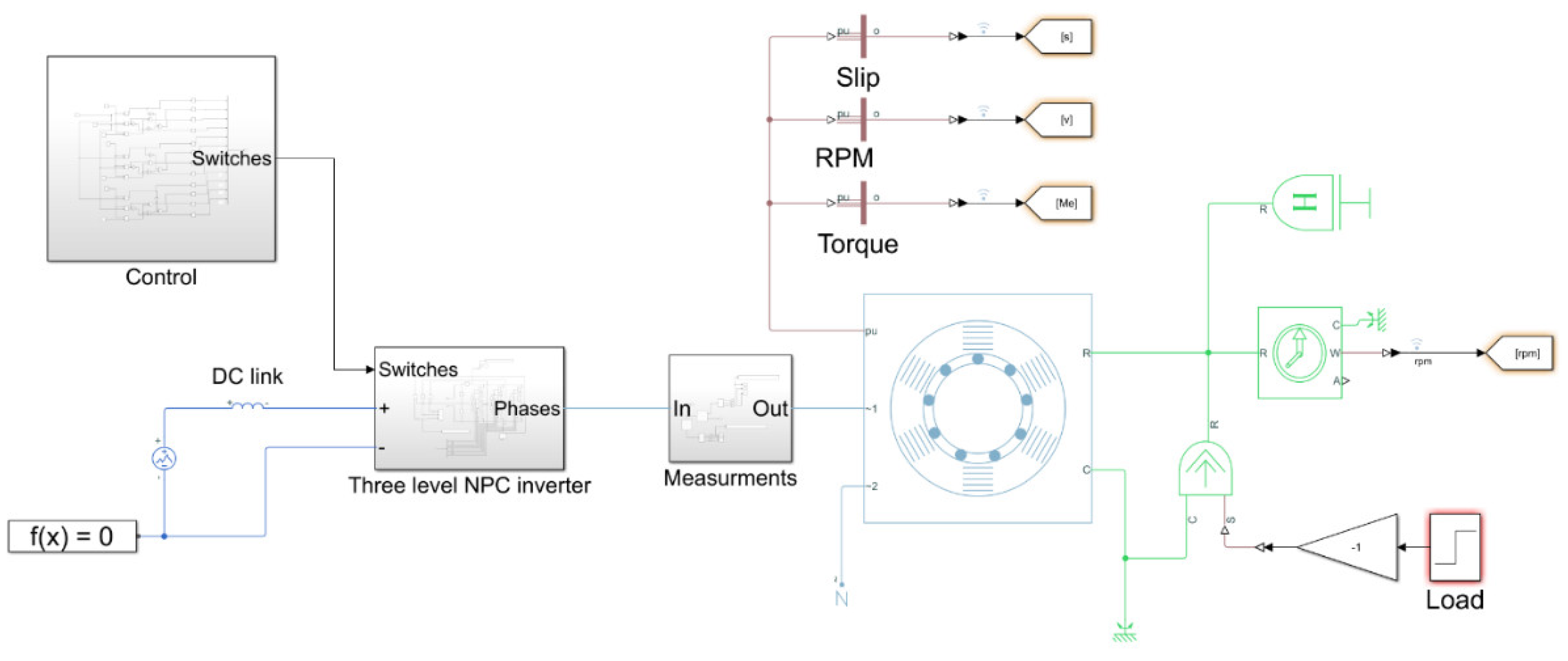
2.3. Simulation Model of Motor Drive Power System
The simulations were carried out using a mathematical model of a three-level inverter in the NPC configuration and an induction motor created in the MATLAB/Simulink environment. Two modulators were designed: SCPWM, which performs synchronous carrier modulation, and an SHE modulator. The SCPWM model is a classic solution consisting of carrier generators, comparators, and switching logic.
Figure 1 shows the entire simulation model.
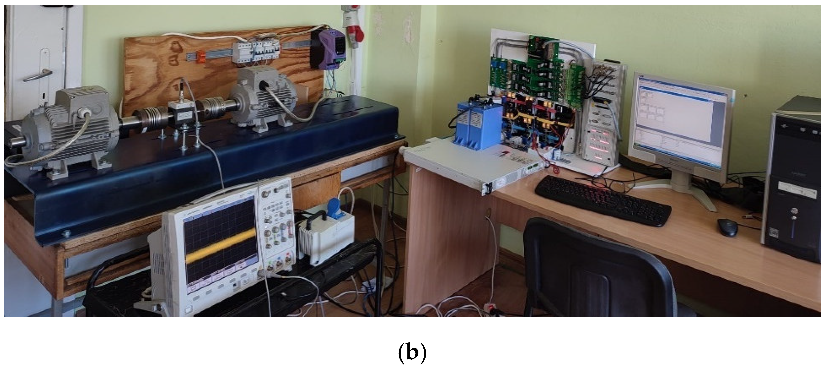
2.4. Laboratory Stand Setup
The simulation tests were validated by performing real experiments on a laboratory stand equipped with a three-level NPC inverter with a CPLD system, laboratory power supply, dSpace 1104 card, PC, induction motor with load, industrial inverter, and ICP603C01 accelerometer. The block diagram of the stand and photograph is depicted in
Figure 2a,b.
The input data for the dSpace card are switching angle tables, obtained offline during the optimalization process described in
Section 2.2. The correct data-fitting modulation index and fundamental frequency were loaded through a MATLAB script to the Simulink workspace. Then, the correct switching sequence was delivered to 12 outputs of the dSpace card. The signal logic was then verified by CPLD to avoid any mistakes resulting in short-circuits and to impose required deadtimes for switching transistors. After passing through CPLD, the switching sequence was delivered to dedicated drivers, which eventually turned IGBT switching keys on and off. In the case of an industrial appliance, where there is no possibility of using MATLAB and a dSpace card, for implementation of the proposed methods, it is sufficient to use the commonly used inverter’s controllers, such as DSPiC32 microcontrollers, or an FPGA system with ARM processors, such as XILINX ZYNQ-7000.
The parameters of the motor drive used in the experiments and simulations are shown in
Table 1.
3. Results
3.1. Simulation Results
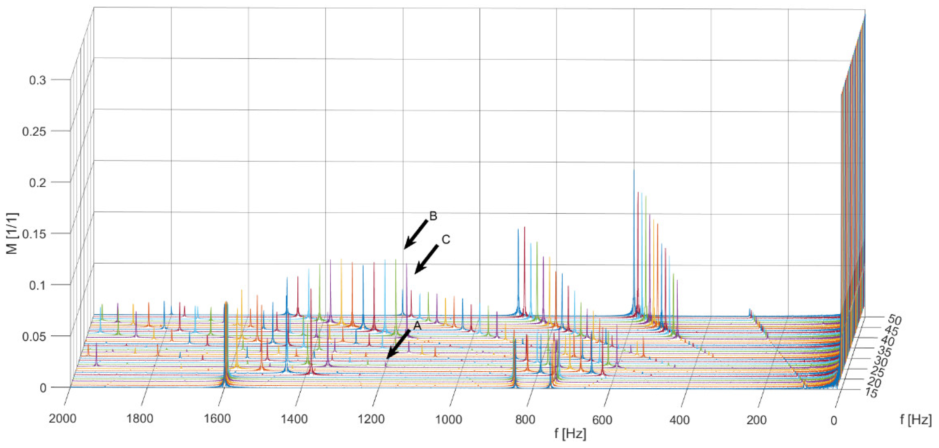
Figure 3 shows a graph of the harmonic spectrum of torque generated in a mathematical model of the propulsion system using the SCPWM method.
The tests were carried out separately for the first harmonic frequencies of the motor supply voltage in the range of 5–50 Hz. For the testing, an assumption was made for each operating point that it is a fixed work point. The values of the modulation coefficient were selected in accordance with the assumption of ensuring a constant flux, i.e., U/f for the frequency of 20–50 Hz. For the frequency of 5–19 Hz, the system operates with a constant switching frequency of 800 Hz. Arrows A, B, and C indicate undesirable harmonic components with a frequency of 1200 Hz for 25, 40, and 50 Hz, respectively, i.e., the frequency of the first harmonic voltage wave.
The conclusion of the research shows that, when working at different frequencies of the first harmonic voltage, an unwanted torque component with a frequency of 1200 Hz appears at the generated torque, which can subsequently lead to mechanical resonance.
The SHE modulator proposed in the article was implemented using tables of switching angles, which were determined at the stage of preliminary research as a result of the optimization algorithm.
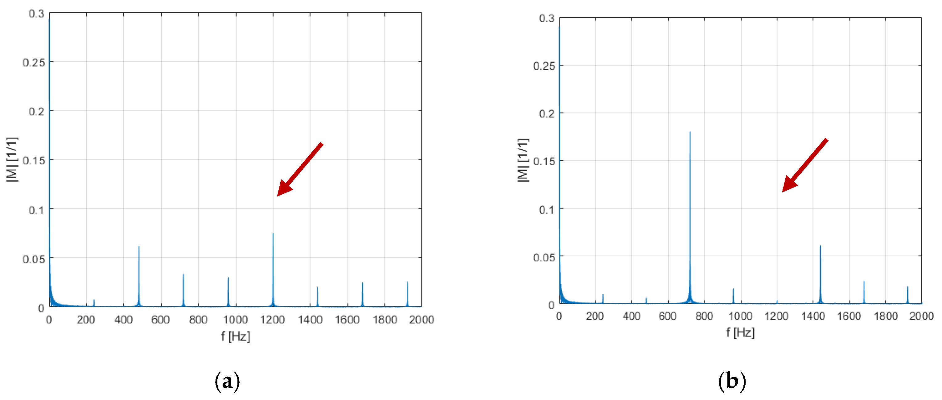
The effect of using the voltage modulation method described above is the production of the desired harmonic spectrum of the torque, through the possibility of eliminating the selected frequency occurring in the torque signal.
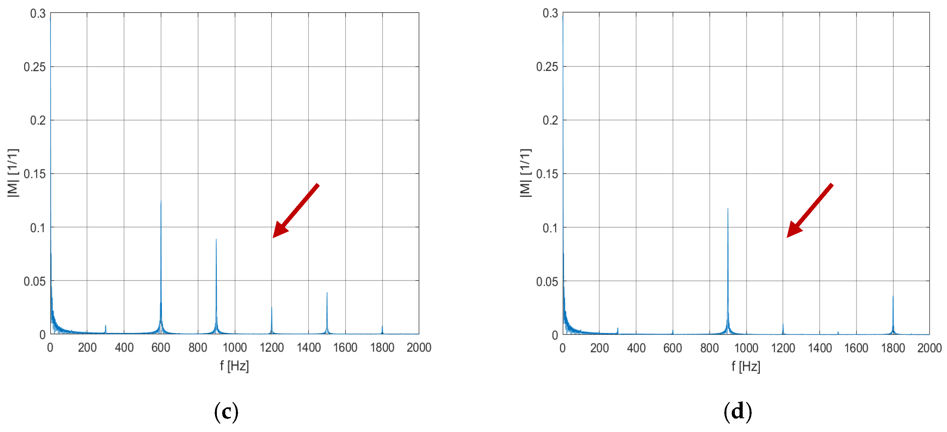
Figure 4 shows a juxtaposition of the torque spectra for the SCPWM method and SHE for two example frequencies of 40 and 50 Hz in which torque harmonics for 1200 Hz occurred.
The switching angles for SHE for two frequency values of 40 and 50 Hz are given in
Table 2.
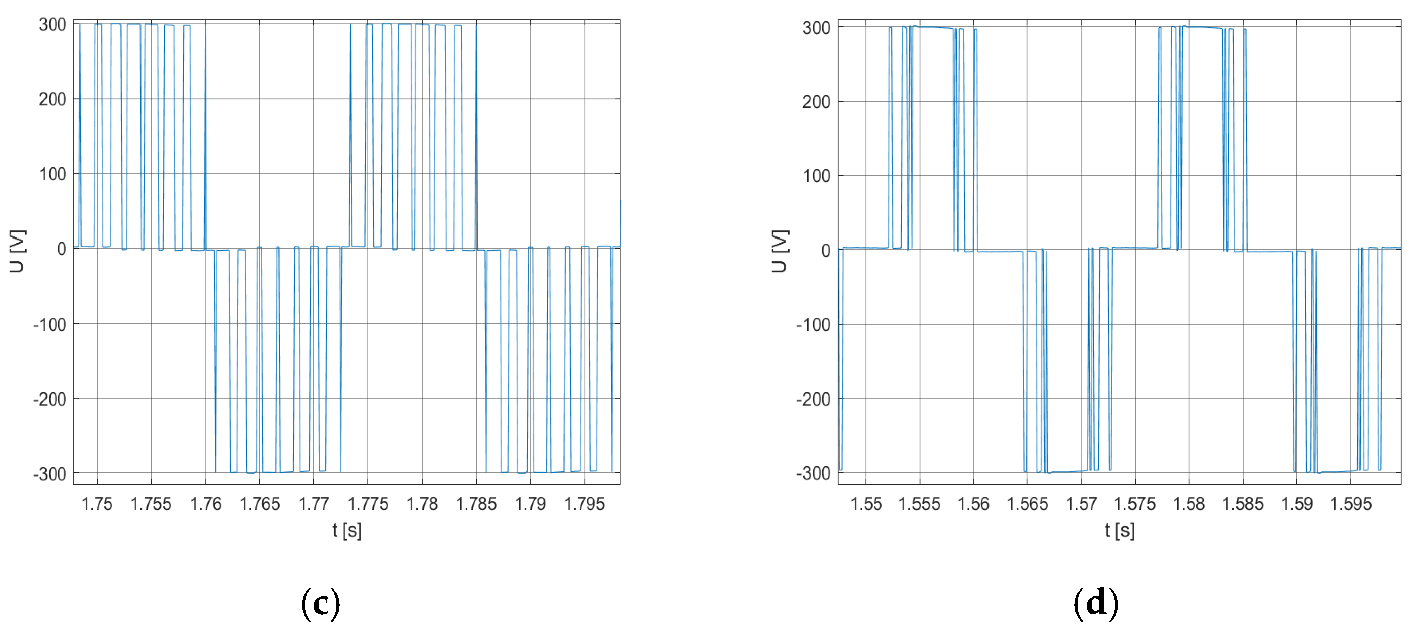
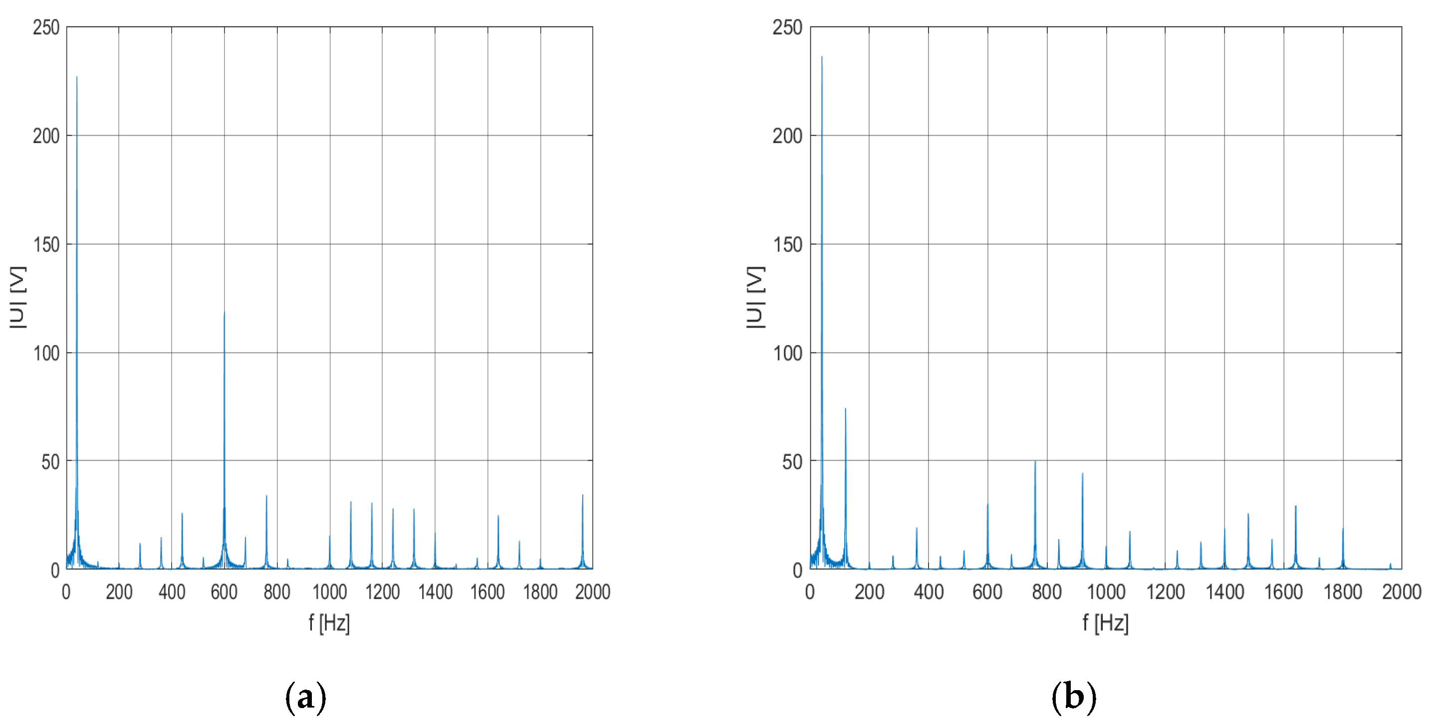
Detailed graphs showing the frequency spectrum and time waveform of the phase voltage are illustrated in
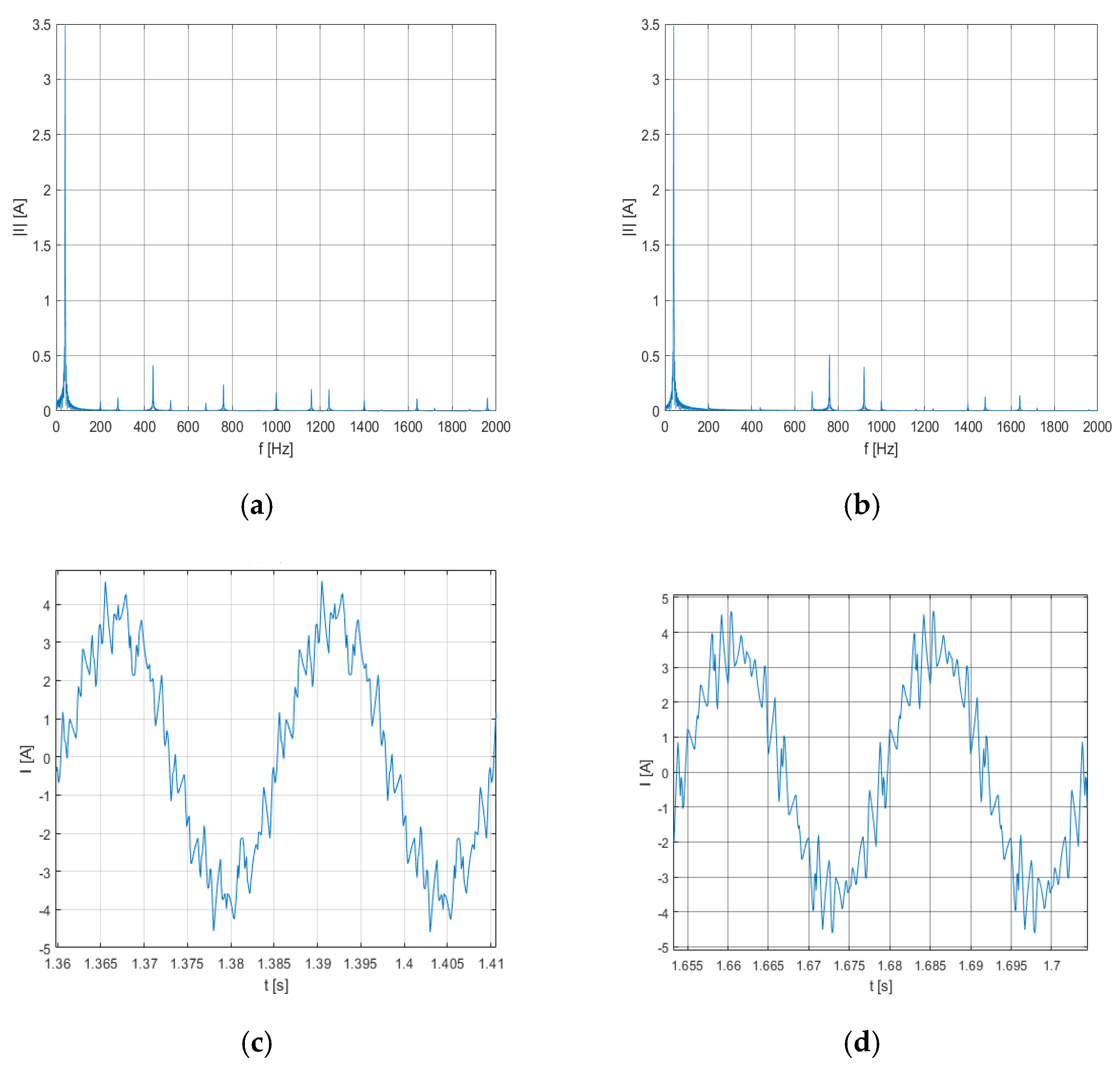
Figure 5. The frequency spectrum and time waveform of the phase current are shown in
Figure 6.
The analysis of individual waveforms from
Figure 4,
Figure 5 and
Figure 6 shows that the SHE method allows for effective elimination of the selected frequency occurring in the torque spectrum (in this case it is 1200 Hz).
Next, the tests showing the influence of the change in the model parameters on the mitigating effect of the SHE algorithm were carried out. During the trials, the authors did not notice any significant changes in the mitigating effect of the proposed algorithm.
3.2. Experimental Results
The essence of the research was the observation of the torque harmonics generated by the motor. Due to the lack of reliable possibilities to directly measure torque for a wide frequency range, it was assumed that the presence of torque disturbances for a given frequency would be seen in the spectrum of vibrations observed in the laboratory stand. For this purpose, a vibration sensor was installed in the base of the bench. The correctness of the assumption is evidenced by the compatibility of the torque harmonic spectra obtained as a part of simulation studies with the harmonic spectra of vibrations observed in laboratory tests. The imperfection of the proposed method is the expression of the results derived from the laboratory tests presenting the harmonics of the torque in the form of the unit of voltage occurring at the output of the sensor.
The tests were carried out for the entire frequency range of the drive system.
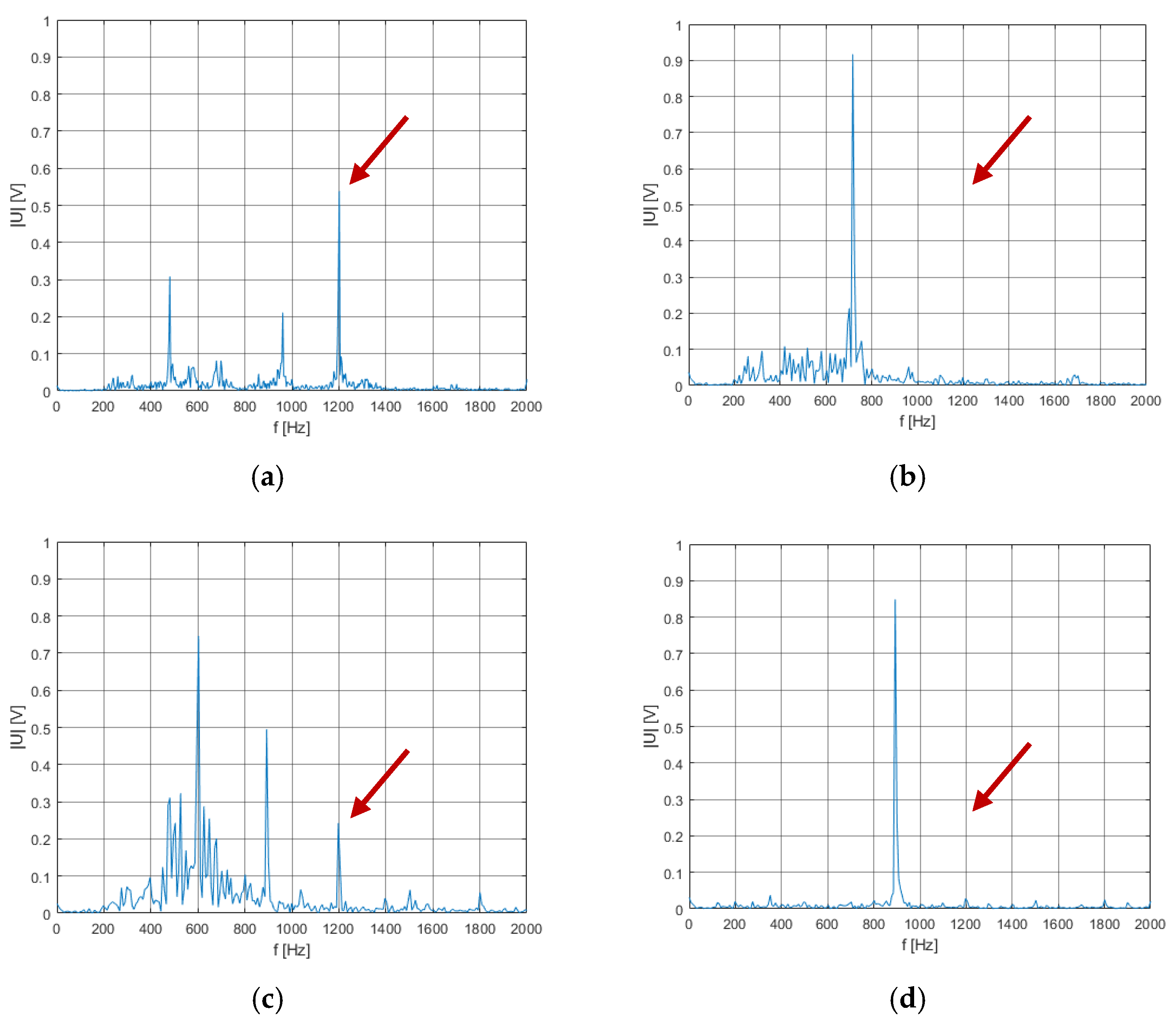
Figure 7 shows the results obtained for the two selected frequencies (40 and 50 Hz).
The waveforms shown illustrate the frequency spectra of the propulsion unit vibrations for the SCPWM and SHE methods. The frequencies of 40 and 50 Hz were chosen because their spectra for SCPWM modulation contained the highest harmonic component values of 1200 Hz. The obtained results show high efficiency in eliminating the selected vibration frequency of 1200 Hz. On all spectral graphs, a high correspondence of the harmonic components for the recorded vibration signal with the harmonic waveforms of the torque obtained by simulation can be observed (comparison of
Figure 4a–d and
Figure 7a–d), further proving the correctness of modeling phenomena in the simulation program and the proper performance of real research. Taking into account the waveforms presented in
Figure 7a–d, the damping factor for 1200 Hz harmonic equals 23.2 for the fundamental frequency of 40 Hz and 12.1 for the fundamental frequency of 50 Hz. This significant improvement allows the avoidance of mechanical resonance that could lead to drive system failure.


