
Fault-Tolerant Control for Reducing Harmonic Distortion of Dual Three-Phase Permanent Magnet Synchronous Motor

Abstract
:1. Introduction
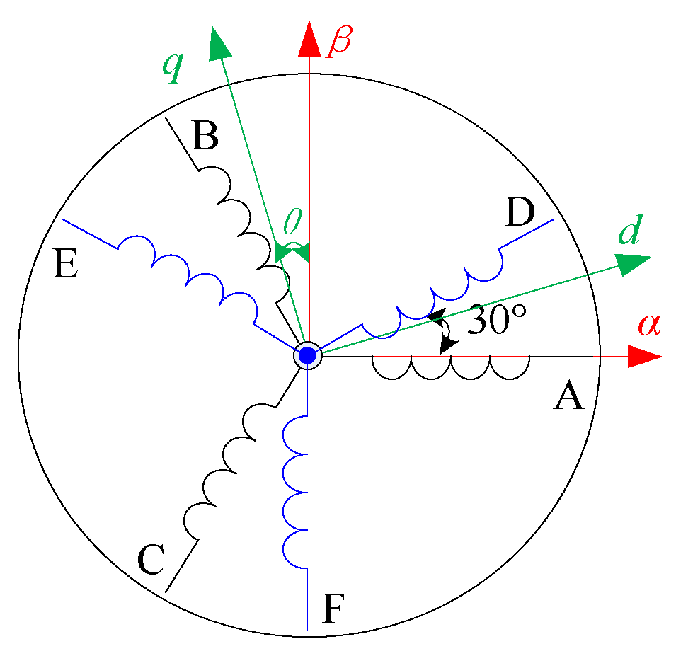
2. Mathematical Model of DTP-PMSM
3. Open Circuit Fault Diagnosis Based on Normalized Current
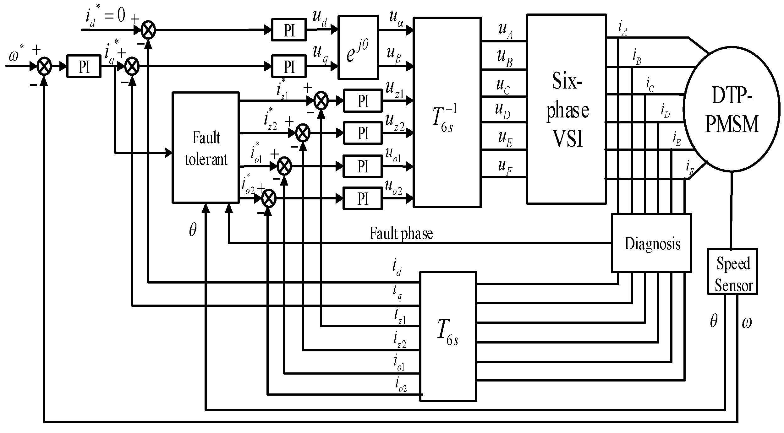
4. Fault-Tolerant Control Strategy for DTP-PMSM
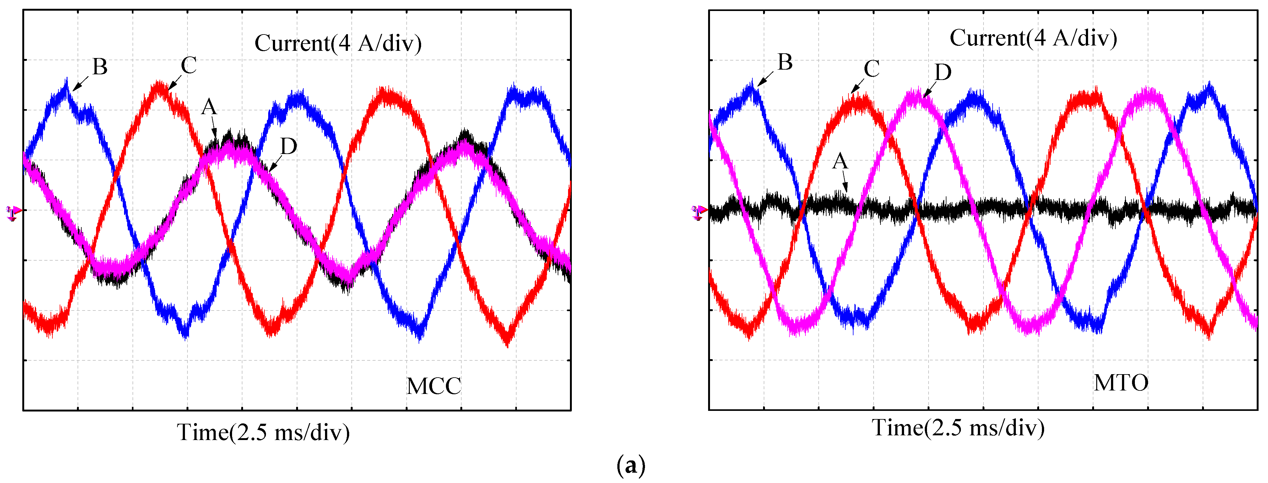
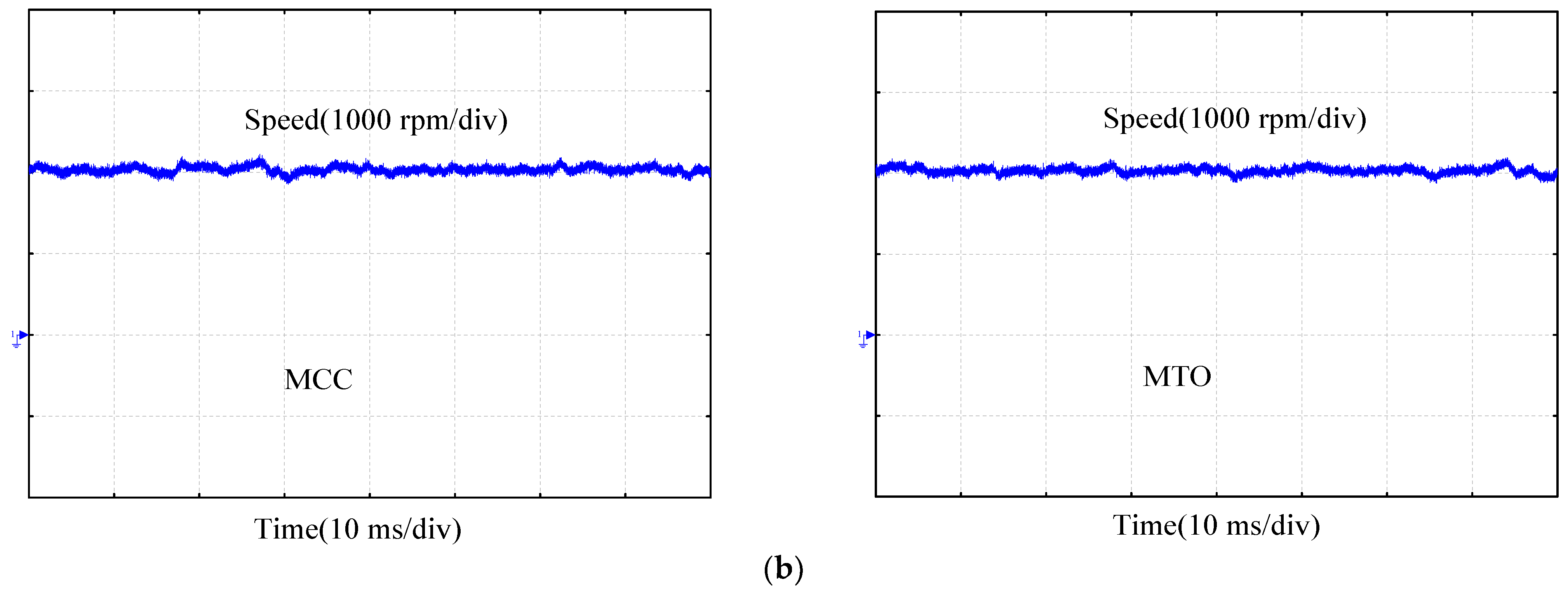
4.1. Current Optimization Objective with MCC
4.2. Current Optimization Objective with MTO
5. Motor Torque Analysis
6. Simulation Analysis and Experimental Results
6.1. Simulation Analysis
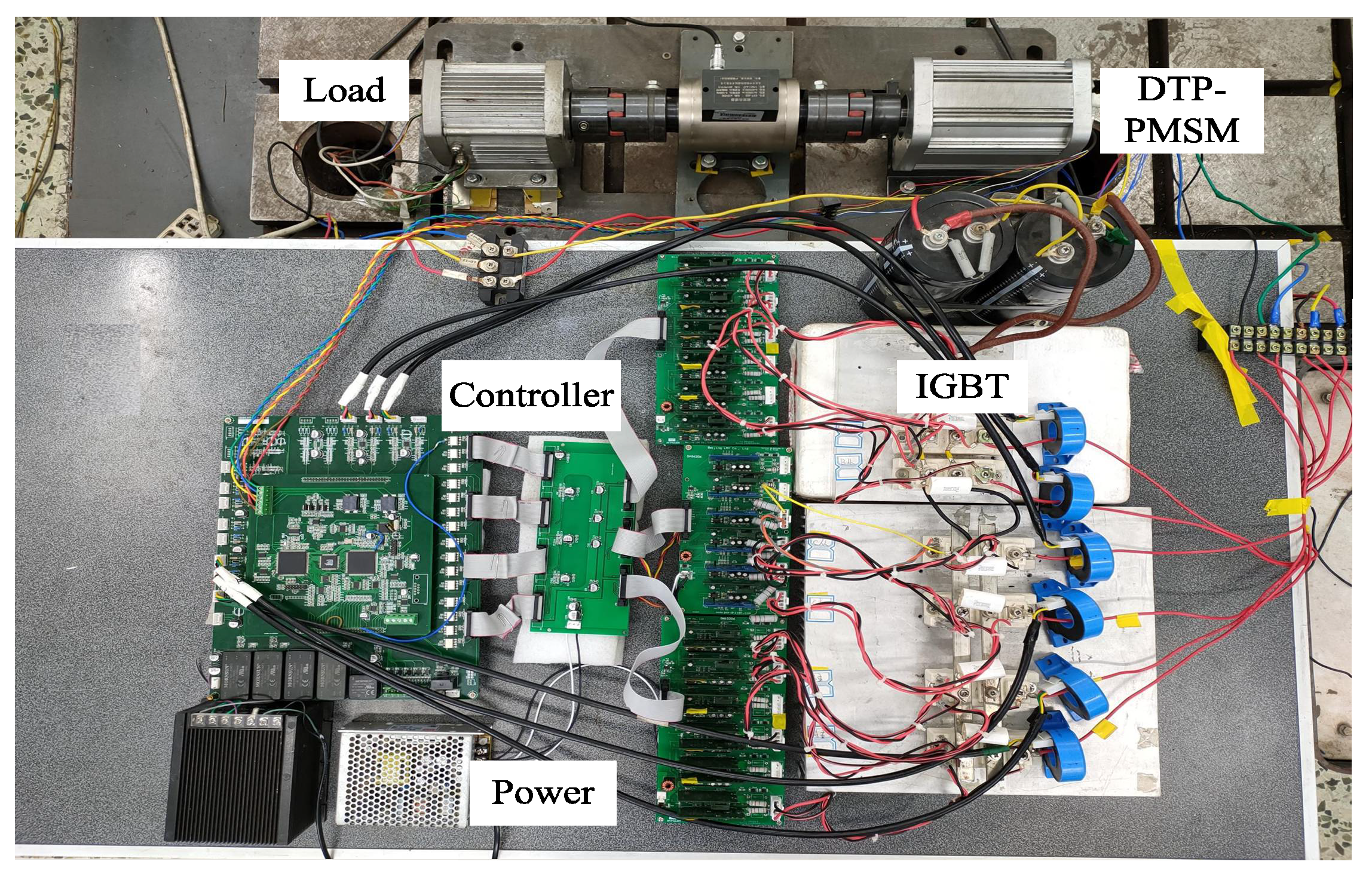
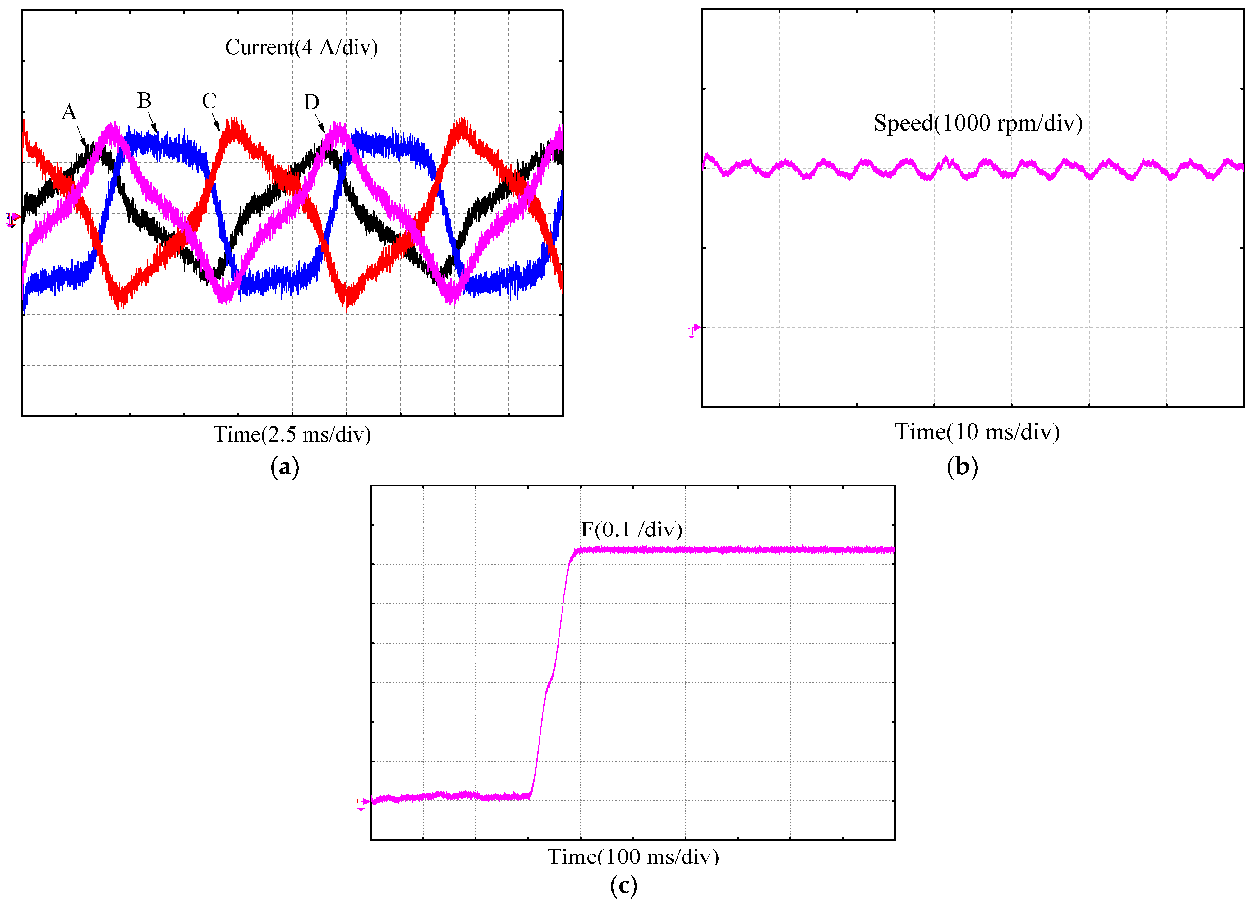
6.2. Experiment Results
7. Conclusions
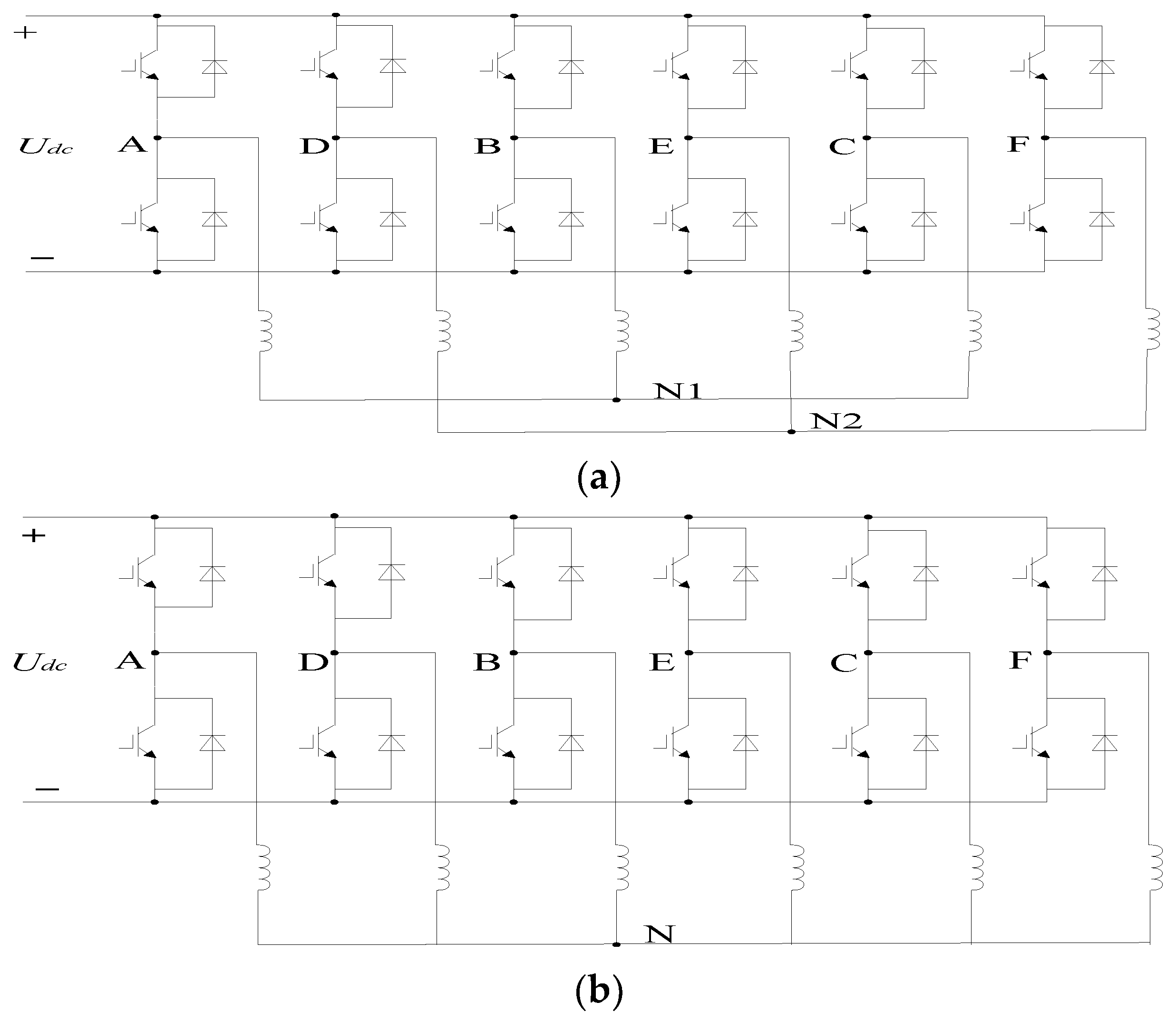
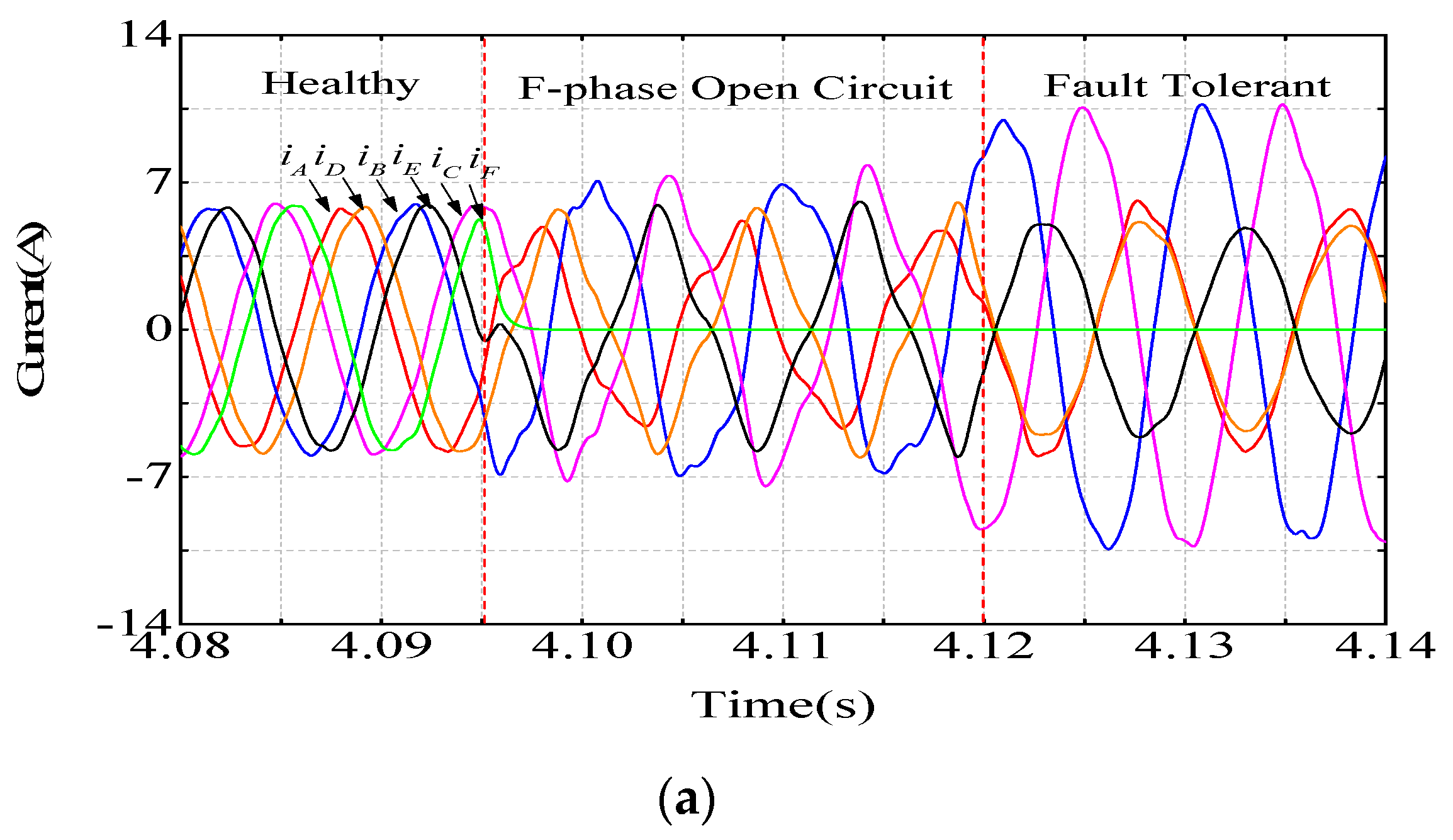
- (a)
- In the study, an open circuit fault diagnosis method based on a normalized current was applied to diagnose the fault phase in order to carry out the corresponding fault-tolerant control strategy.
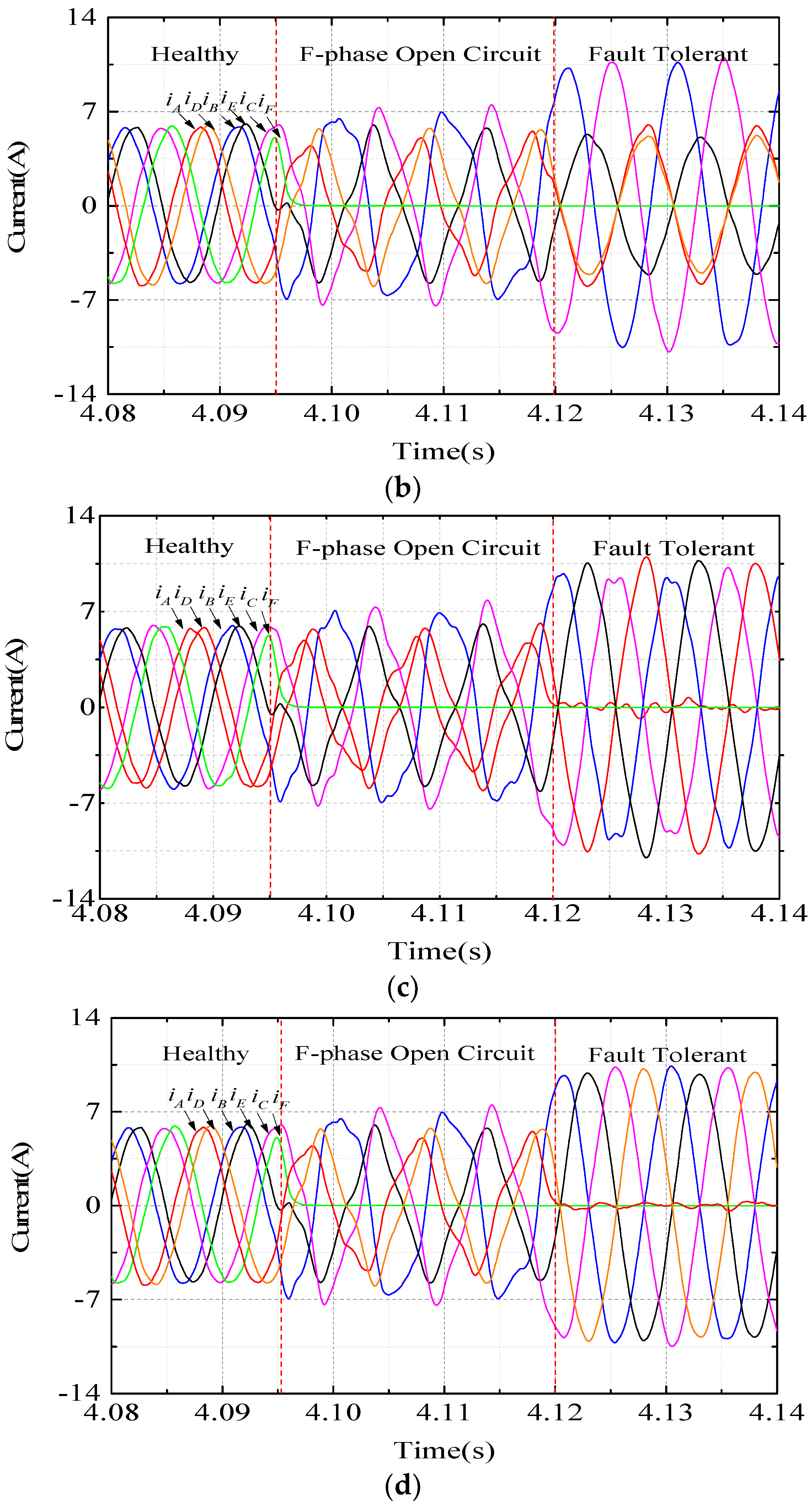
- (b)
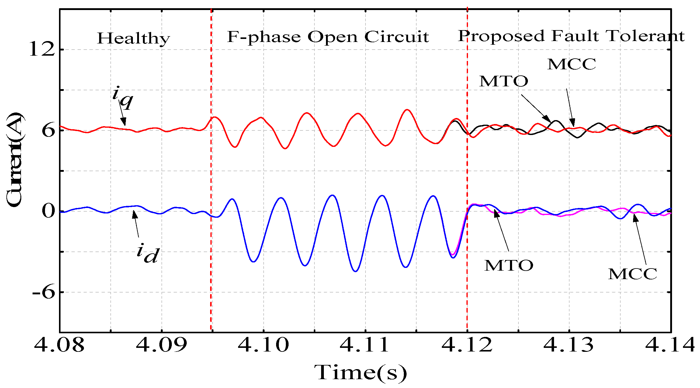
- A novel fault-tolerant control strategy based on MPC was proposed for the purpose of reducing the harmonic distortion and improving fault tolerance performance. It adjusts the current setting of z1-z2 and o1-o2 subspace without changing the mathematical model of the motor. The fault-tolerant control strategy is studied by taking the proposed MCC and MTO as the optimization objectives.
Author Contributions
Funding
Conflicts of Interest
References
- Jia, S.; Liu, Z.; Liang, D. Review of fault tolerant control strategies for multiphase motors [J/OL]. J. Xi’an Jiaotong Univ. 2021, 6, 1–9. [Google Scholar]
- Chen, B.; Lv, J.; Jiang, X. Simplified Model Predictive Control of a Twelve-Phase Permanent Magnet Synchronous Motor. In Proceedings of the IECON 2019—45th Annual Conference of the IEEE Industrial Electronics Society, Lisbon, Portugal, 19 April 2019; pp. 1345–1350. [Google Scholar]
- Xu, J.; Zhang, B.; Fang, H.; Guo, H. Guaranteeing the fault transient performance of aerospace multiphase permanent magnet motor system: An adaptive robust speed control approach. CES Trans. Electr. Mach. Syst. 2020, 4, 114–122. [Google Scholar] [CrossRef]
- Barrero, F.; Duran, M.J. Recent advances in the design, modeling and control of multiphase machines—Part 1. IEEE Trans. Ind. Electron. 2016, 63, 449–458. [Google Scholar] [CrossRef]
- Feng, G.; Lai, C.; Li, W.; Tjong, J.; Kar, N.C. Open-Phase Fault Modeling and Optimized Fault-Tolerant Control of Dual Three-Phase Permanent Magnet Synchronous Machines. IEEE Trans. Power Electron. 2016, 34, 11116–11127. [Google Scholar] [CrossRef]
- Zheng, L.; Yang, O.; Lin, H.; Chao, M.; Siguo, Z. Vector control system of multi-level double y-shift 30° permanent magnet synchronous motor. Acta Electrotech. Sin. 2016, 31, 45–56. [Google Scholar]
- Ma, X.; Zheng, A.; Zhang, H.; Liu, L. Sliding mode variable structure control technology for double y-shift 30° six phase PMSM. J. Electr. Mach. Control 2018, 22, 1292. [Google Scholar]
- Gaeta, A.; Scelba, G.; Consoli, A. Modeling and control of three-phase PMSMs under open-phase fault. IEEE Trans. Ind. Appl. 2013, 49, 74–83. [Google Scholar] [CrossRef]
- Gao, C.; Zhao, W.; Ji, J.; Chen, Q. Low harmonic double three phase permanent magnet synchronous motor and its fault tolerant control. Acta Electrotech. Sin. 2017, 32, 124–130. [Google Scholar]
- Hosseyni, A.; Trabelsi, R.; Mimouni, M.F.; Iqbal, A. Fault tolerant control strategy of a five-phase permanent magnet synchronous motor drive. In Proceedings of the 16th International Conference on Sciences and Techniques of Automatic Control and Computer Engineering (STA), Monastir, Tunisia, 19 April 2015; pp. 218–222. [Google Scholar]
- Wang, S.; Chen, R.; Lee, F.C.; van Wyk, J.D. Improved passive filter configurations for high-frequency conducted EMI in power electronics. In Proceedings of the IEEE European Power Electronics, Dresden, Germany, 11–14 September 2005. [Google Scholar]
- Liu, H.T.; Fu, R.J.; Lipo, A.T. A strategy for improving reliability of fifield-oriented controlled induction motor drives. IEEE Trans. Ind. Appl. 1993, 29, 910–918. [Google Scholar]
- Fu, R.J.; Lipo, A.T. Disturbance-free operation of a multiphase current-regulated motor drive with an open phase. IEEE Trans. Ind. Appl. 1994, 30, 1267–1274. [Google Scholar]
- Yao, G.; Yin, Z.; Zhou, L.; Wang, J. Fault tolerant control of six phase permanent magnet synchronous generator. J. Electr. Mach. Control 2018, 22, 1–10. [Google Scholar]
- Gao, H.; Yang, G. Modeling and control of five phase permanent magnet synchronous motor in open phase operation. Acta Electrotech. Sin. 2016, 31, 93–101. [Google Scholar]
- Yang, Z. Research on Fault Tolerant Control Strategy of Dual Three Phase Permanent Magnet Synchronous Motor; Harbin Institute of Technology: Harbin, China, 2018. [Google Scholar]
- Zhou, C.; Tang, W.; Sun, X.; Zhou, Z.; Yang, G.; Su, J. Control strategy for dual three-phase PMSM based on reduced order mathematical model under fault condition due to open phases. J. Eng. 2018, 2018, 489–494. [Google Scholar]
- Zhao, M.; Quan, L.; Zhang, C.; Zhu, X. Single phase open circuit fault decoupling fault tolerant control of five phase permanent magnet synchronous motor based on minimum copper consumption. Appl. Mot. Control 2017, 44, 126–133. [Google Scholar]
- Yang, J.; Li, T.; Yang, G. Modeling and control of one phase open circuit double three phase permanent magnet synchronous motor. Acta Electrotech. Sin. 2011, 26, 5862–5872. [Google Scholar]
- Giangrande, P.; Madonna, V.; Nuzzo, S.; Spagnolo, C.; Gerada, C.; Galea, M. Reduced Order Lumped Parameter Thermal Network for Dual Three-Phase Permanent Magnet Machines. In Proceedings of the 2019 IEEE Workshop on Electrical Machines Design, Control and Diagnosis (WEMDCD), Athens, Greece, 22–23 April 2019; pp. 71–76. [Google Scholar]
- Zhang, W.; Xu, Y.; Chen, B. Control of Dual Three-Phase Permanent Magnet Synchronous Motor under Open Phase Fault Conditions. In Proceedings of the 2016 IEEE Vehicle Power and Propulsion Conference (VPPC), Hangzhou, China, 11 December 2016; pp. 1–5. [Google Scholar]
- Zhao, Y.; Lipo, T.A. Modeling and control of a multi-phase induction machine with structural unbalance. IEEE Trans. Energy Convers. 1996, 11, 570–577. [Google Scholar] [CrossRef]
- Ryu, M.H.; Kim, W.J.; Sul, K.S. Synchronous-frame current control of multiphase synchronous motor under asymmetric fault condition due to open phases. IEEE Trans. Ind. Appl. 2006, 42, 1062–1070. [Google Scholar]
- Tian, D.; Chen, L.; Hou, L.J.; Pan, J. Modeling and simulation of dual three-phase induction machine with two opened phases. In Proceedings of the IEEE International Conference on Industrial Technology, Chengdu, China, 21–24 April 2008; pp. 1–5. [Google Scholar]
- Tiao, S.; Zhou, M.; Ouyang, H.L.; Liu, L. Vector control of multiphase PMSM with asymmetric structure. Trans. China Electrotech. Soc. 2004, 19, 37–41. [Google Scholar]
- Wang, W.; Zhang, J.; Cheng, M.; Li, S. Fault-Tolerant Control of Dual Three-Phase Permanent-Magnet Synchronous Machine Drives Under Open-Phase Faults. IEEE Trans. Power Electron. 2016, 32, 2052–2063. [Google Scholar] [CrossRef]
- Fan, Y. Research on Control Strategy of Five Phase Permanent Magnet Synchronous Motor Based on Third Harmonic Injection; Harbin Institute of Technology: Harbin, China, 2016. [Google Scholar]
- Feng, G.; Lai, C.; Kelly, M.; Kar, N.C. Dual Three-Phase PMSM Torque Modeling and Maximum Torque per Peak Current Control Through Optimized Harmonic Current Injection. IEEE Trans. Ind. Electron. 2018, 66, 3356–3368. [Google Scholar] [CrossRef]
- Zhou, C.; Yang, G.; Su, J.; Sun, G. Open phase fault tolerant control strategy of dual three phase permanent magnet synchronous motor based on normal decoupling transformation. Acta Electrotech. Sin. 2017, 32, 86–96. [Google Scholar]
- Locment, F.; Semail, E.; Kestelyn, X. Vectorial approach-based control of a seven-phase axial flflux machine designed for fault operation. IEEE Trans. Ind. Electron. 2008, 55, 3682–3691. [Google Scholar] [CrossRef] [Green Version]
- Tani, A.; Mengoni, M.; Zarri, L.; Serra, G.; Casadei, D. Control of multiphase induction motors with an odd number of phases under opencircuit phase faults. IEEE Trans. Power Electron. 2012, 27, 565–577. [Google Scholar] [CrossRef]
- Akay, A.; Lefley, P.; Kansara, M. Open-Circuit Fault-Tolerant Control for a Five-Phase Permanent Magnet Synchronous Machine Drive. In Proceedings of the 2020 7th International Conference on Electrical and Electronics Engineering (ICEEE), Antalya, Turkey, 14–16 April 2020; pp. 150–154. [Google Scholar]
- Yu, Y. Research on Control Technology of Double y-Shift 30° Six Phase Permanent Magnet Synchronous Motor; Harbin Institute of Technology: Harbin, China, 2015. [Google Scholar]


| MCC | MTO | |||||||
|---|---|---|---|---|---|---|---|---|
| Fault phase | Structure 1 | Structure 2 | Structure 1 | Structure 2 | ||||
| Loss | Imax | Loss | Imax | Loss | Imax | Loss | Imax | |
| A | ||||||||
| A,D (30°) | ||||||||
| A,F (90°) | ||||||||
| A,B (120°) | ||||||||
| A,E (150°) | ||||||||
| Parameter | Value |
|---|---|
| Rated power | 1.5 kw |
| Rated current | 6 A |
| Motor stator resistance | 0.72 Ω |
| d-axis inductance Ld | 1.65 mH |
| q-axis inductance Lq | 1.65 mH |
| Flux linkage | 0.13 Wb |
| Pole pairs | 3 |
| Rated speed n | 2000 r/min |
Publisher’s Note: MDPI stays neutral with regard to jurisdictional claims in published maps and institutional affiliations. |
© 2022 by the authors. Licensee MDPI, Basel, Switzerland. This article is an open access article distributed under the terms and conditions of the Creative Commons Attribution (CC BY) license (https://creativecommons.org/licenses/by/4.0/).
Share and Cite
Zhao, L.; Ge, B.; Gao, H.; Tao, D. Fault-Tolerant Control for Reducing Harmonic Distortion of Dual Three-Phase Permanent Magnet Synchronous Motor. Energies 2022, 15, 3887. https://doi.org/10.3390/en15113887
Zhao L, Ge B, Gao H, Tao D. Fault-Tolerant Control for Reducing Harmonic Distortion of Dual Three-Phase Permanent Magnet Synchronous Motor. Energies. 2022; 15(11):3887. https://doi.org/10.3390/en15113887
Chicago/Turabian StyleZhao, Liping, Baojun Ge, Hanying Gao, and Dajun Tao. 2022. "Fault-Tolerant Control for Reducing Harmonic Distortion of Dual Three-Phase Permanent Magnet Synchronous Motor" Energies 15, no. 11: 3887. https://doi.org/10.3390/en15113887
APA StyleZhao, L., Ge, B., Gao, H., & Tao, D. (2022). Fault-Tolerant Control for Reducing Harmonic Distortion of Dual Three-Phase Permanent Magnet Synchronous Motor. Energies, 15(11), 3887. https://doi.org/10.3390/en15113887