Article

Coupling Analysis of Electromagnetic Vibration and Noise of FeCo-Based Permanent-Magnet Synchronous Motor

National Engineering Research Center of Large Electric Machines and Heat Transfer Technique, Harbin University of Science and Technology, Harbin 150080, China
*
Author to whom correspondence should be addressed.
Energies 2022, 15(11), 3888; https://doi.org/10.3390/en15113888
Submission received: 16 April 2022 / Revised: 6 May 2022 / Accepted: 10 May 2022 / Published: 25 May 2022
(This article belongs to the Special Issue Design, Analysis and Control of Permanent Magnet Machines)

Abstract

:
Addressing the problem of the vibration and noise of a permanent-magnet synchronous motor (PMSM), this paper optimizes the structure of a permanent-magnet motor rotator, introduces the electromagnetic-structure-acoustic coupling calculation model, and optimizes the motor rotator to reduce the vibration and noise of a permanent-magnet motor. Using the theory of Maxwell’s stress equation, the radial electromagnetic force on the stator teeth of the permanent-magnet motor is deduced and analyzed, and the correctness of the analysis calculation is verified by using the finite element multi-physical field coupling method. Based on the deduced analytical expression of the radial electromagnetic force, the sources of the radial electromagnetic force for each order and the frequency of the permanent-magnet motor are summarized. A 12-slot, 8-pole, permanent-magnet motor is taken as an example. A calculation model considering the spatial distribution of the radial electromagnetic force and the electromagnetic vibration of an iron-cobalt-based stator is established. The harmonic response of the electromagnetic vibration of the motor is analyzed, and a modal analysis is carried out. The optimized acceleration vibration noise cascade of the FeCo-based permanent-magnet drive motor under load is given. The correctness and validity of the theoretical derivation and simulation are verified by experiments.

1. Introduction

Vibration and noise are two of the indices used to measure the quality of a permanent-magnet motor. Because of its high efficiency and simple structure, a permanent-magnet motor is widely used in various fields. Therefore, studying the vibration and noise of a permanent-magnet motor has important practical significance.
The electromagnetic vibration noise of a permanent-magnet motor (PMSM) is a problem in the coupling of multiple physical fields, such as electromagnetic, mechanical, structure, and sound fields. At present, the main research methods of PMSM electromagnetic vibration noise include the analytical method, the finite element method, and the experimental method [1,2,3]. In [4,5], the authors optimize the thickness and slot shape of the stator yoke of a permanent-magnet motor to reduce the vibration noise of the motor. In [6], the authors compare different stator/rotor and slot/pole combinations, and it is found that the vibration noise of the motor is usually determined by its lowest order radial force harmonic, followed by the frequency of the radial force and, finally, by the amplitude. In [7,8], the vibration displacement and the acceleration of stator housing under electromagnetic force waves are analyzed using the finite element method, and the vibration and noise performances of the motor are accurately predicted. In [9,10], the authors study the relationship between the slot width and radial electromagnetic force. Opening auxiliary slots in the stator can suppress the low-order electromagnetic force to optimize the electromagnetic vibration noise. In [11], the author presents a method of pasting copper rings on permanent magnets to reduce the high-frequency component of motor vibration. Reference [12] discusses the influence of the shape of the permanent-magnet pole on vibration under no-load and rated load conditions. References [13,14,15] use the finite element method to analyze, in detail, the influence of the structure parameters of the fixed rotor on the low-order electromagnetic excitation force wave. It can be seen from the above literature that the components of the radial electromagnetic force can be accurately obtained by using the finite element method, but the calculation takes a long time. Furthermore, it is difficult to obtain the magnetic potential of each order, and it is more difficult to determine the corresponding relationship with the electromagnetic force of each order diameter, which is not conducive to the analysis of electromagnetic force and the precise calculation of vibration and noise.
In [16,17,18], the authors use the finite element method to calculate the modes of the stator but only for specific surface-mounted permanent-magnet structure motors; in particular, when changing the size parameters of the stators to optimize their natural frequencies, the computational load is too large, and the limitations are obvious. In [19,20,21,22], the authors use the two-dimensional time-stepped finite element method to accurately calculate the radial force of a permanent-magnet motor. The influence of the combination of the pole and slot on the vibration and noise of the motor is analyzed in detail. The auxiliary slot in the stator can suppress the low-order electromagnetic force to optimize the electromagnetic vibration and noise, but the derivation process is relatively complex. Reference [23] conducts a comparative analysis on the electromagnetic vibration noise and electromagnetic characteristics of three kinds of motors, namely, a permanent-magnet motor, an excitation motor, and a reluctance motor, because of the large error in the results calculated using the analytic method. In [24,25,26], the authors calculate the electromagnetic vibration noise of a permanent-magnet motor using the analytic method without considering the sound radiation efficiency, so the calculation accuracy is limited. Since the motor of an electric vehicle usually works in a wide speed range, it is often necessary to predict the vibration and noise of the motor in a full speed range.
In order to overcome the shortage of single solution calculation of the analytical method and finite element method, this paper aims to explore the method of multi-physical field coupling to quickly and accurately predict the electromagnetic vibration and noise of permanent-magnet synchronous motors. This paper takes a 30 kW permanent-magnet synchronous motor with a rated speed of 4000 r/min as the research object. This paper uses a combination of the finite element method and the analytical method to accurately calculate the motor vibration and noise of silicon steel and iron cobalt (FeCo)-based stator materials. Through a comparison of these two stator materials and the optimization of te rotor structure, the vibration and noise of the motor with two stator materials are restrained. Finally, the correctness of the simulation and theoretical derivation is verified by an experiment with the FeCo-based permanent-magnet motor.

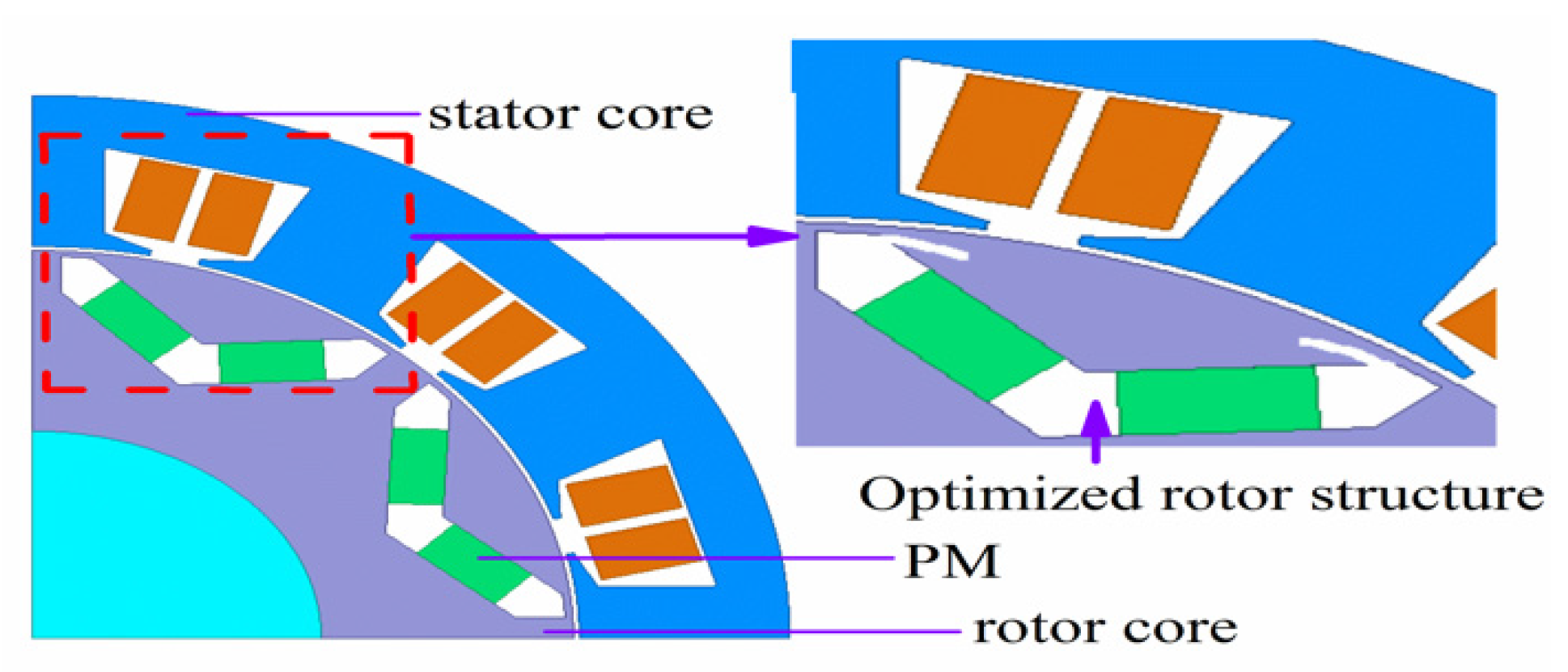
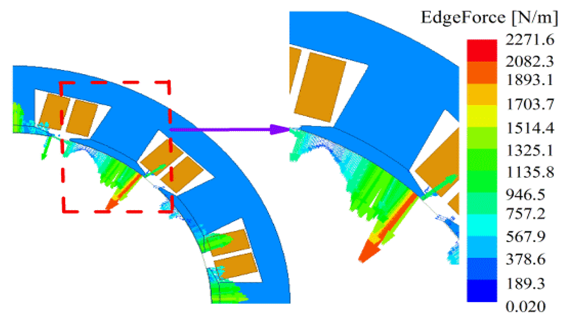
2. Motor Structure of FeCo Based Materials

A section diagram of the PMSM used in this study is shown in Figure 1. The motor is an 8-pole, 12-slot, fractional-slot, double-layer, concentrated winding PMSM. The permanent-magnet structure of the rotor is V-shaped, which is equivalent to four 3-slot, 2-pole unit motors stitched in turn on the circumference. Its main parameters are shown in Table 1.

3. Electromagnetic Force of PMSM

3.1. Armature Magnetic Potential of Stator Winding

According to the principle of electromagnetics, the ν-th harmonic magnetic potential of single-phase winding can be expressed as
F c ( α , t ) = ν F m ν cos ( ω t ) cos ( ν π τ α )
where F is the amplitude of the ν-th harmonic magnetic potential, ω is the electrical angular velocity, τ is the pole distance, α is the angular displacement, t is the time, ν is the harmonic order, and p is the number of pole pairs.
The stator winding of a three-phase PMSM is three-phase symmetrical winding with a space difference of 120 degrees. The stator is connected to the three-phase sinusoidal AC, and the three-phase current is balanced. Based on the principle of the single-phase winding magnetic potential in the electromagnetic field of the motor, it is known that the time–space function of the winding air-gap magnetic potential under the three-phase sinusoidal AC excitation is
F 1 A ( α , t ) = ν = 1 , 3 , 5 F m ν cos ( ω t ) cos ( ν p α ) = 1 2 ν = 1 , 3 , 5 F m ν cos ( ω t ν p α ) + 1 2 ν = 1 , 3 , 5 F m ν cos ( ω t + ν p α )
F 1 B ( α , t ) = ν = 1 , 3 , 5 F m ν cos ( ω t 2 π 3 ) cos [ ν ( p α 2 π 3 ) ] = 1 2 ν = 1 , 3 , 5 F m ν cos [ ( ω t ν p α ) + ( ν 1 ) 2 π 3 ] + 1 2 ν = 1 , 3 , 5 F m ν cos [ ( ω t ν p α ) ( ν + 1 ) 2 π 3 ]
F 1 C ( α , t ) = ν = 1 , 3 , 5 F m ν cos ( ω t 4 π 3 ) cos [ ν ( p α 4 π 3 ) ] = 1 2 ν = 1 , 3 , 5 F m ν cos [ ( ω t ν p α ) + 2 ( ν 1 ) 2 π 3 ] + 1 2 ν = 1 , 3 , 5 F m ν cos [ ( ω t ν p α ) 2 ( ν + 1 ) 2 π 3 ]
When the harmonic order ν = 3k, (k = 1, 3, 5, …), the difference between each phase is 120 degrees, and the sum of the harmonics is equal to 0. Therefore, there is no harmonic order where ν = 3k in three-phase symmetric windings. When the harmonic order ν = 6k + 1, that is, ν = 1, 7, 13, …each phase of these harmonics differs by a 0 electrical angle, the sum of the vectors is equal to the arithmetic sum, and the rotation direction of the harmonic synthetic magnetic potential is the same as that of the fundamental synthetic magnetic potential. When the harmonic order ν = 6k − 1, or ν = 5, 11, 17, …the difference between each phase is 240 degrees, the sum of the vectors is equal to 0, and the rotation direction of the harmonic synthetic magnetic potential is the opposite to that of the fundamental synthetic magnetic potential. In three-phase symmetric winding, when the three-phase current is balanced, the ν-th magnetic potential of the stator winding is
F 1 ( α , t ) = ν = 1 F m ν cos ( ν p α ω t )

3.2. Rotor’s Permanent-Magnet Magnetic Potential

When the stator armature winding and the stator cogging of PMSM are not considered, the magnetic potential generated by the permanent magnet can be expressed as
F 2 ( α , t ) = μ = 1 F m μ cos ( μ p α ω μ t + ϕ μ )
where the absolute value of μ is the harmonic number; the positive and negative signs represent the forward rotation and reverse rotation of the harmonic magnetic field, respectively; F is the μ amplitude of the sub-permanent-magnet harmonic magnetic potential; ωμ is the μ angular frequency of subharmonic; and ϕμ is the initial phase of the magnetic potential.

3.3. Calculation of Air-Gap Permeance

Without considering the influence of rotor eccentricity and assuming that the rotor surface is smooth, the air-gap permeance can be approximately made up of two parts. One part is the constant permeance, and the other part is the harmonic permeance caused by stator slotting. The analytical expression of the equivalent air-gap permeance is
Λ g ( α ) = Λ g 0 + k = 0 , 1 , 2 , Λ g 0 Λ k cos ( k Z α )
where Ʌg0 is the average magnetic conductance of the air gap, and k is the order of the tooth harmonic; Ʌk is the amplitude of the k-order tooth harmonic magnetic conductivity in the air gap, and Z is the number of slots.

3.4. Radial Electromagnetic Force Density of PMSM

The functional relationship between the air-gap magnetic density b(α,t) and the magnetic potential F(α,t) is as follows:
b ( α , t ) = [ F 1 ( α , t ) + F 2 ( α , t ) ] Λ g ( α , t ) = ν = 1 B m ν cos ( ν p α ω t ) + μ = 1 B m μ cos ( μ p α ω μ t + ϕ μ ) = b 1 ( α , t ) + b 2 ( α , t )
where b1(α,t) is the part generated by the stator winding, b2(α,t) is the part generated by the rotor’s permanent magnet, B is the amplitude of the armature reaction harmonic flux density generated by the ν-th harmonic magnetic potential acting on the average air-gap magnetic conductivity, and B is the amplitude of the armature reaction harmonic flux density generated by the μ-th harmonic magnetic potential acting on the average air-gap magnetic conductivity.
According to Maxwell’s stress tensor method, the radial and tangential electromagnetic force densities in the air gap are
P r ( α , t ) = 1 2 μ 0 [ b r 2 ( α , t ) b t 2 ( α , t ) ]
P t ( α , t ) = 1 μ 0 b r ( α , t ) b t ( α , t )
P r ( α , t ) b 2 2 μ 0 = [ b 1 ( α , t ) + b 2 ( α , t ) ] 2 2 μ 0 = [ b 1 ( α , t ) ] 2 + 2 b 1 ( α , t ) b 2 ( α , t ) + [ b 2 ( α , t ) ] 2 2 μ 0
where Pr(α,t) is the radial electromagnetic force density, Pt(α,t) is the tangential electromagnetic force density, br(α,t) is the radial magnetic density of the air gap, bt(α,t) is the tangential magnetic density of the air gap, and μ0 is the vacuum permeability.
The radial electromagnetic force density in the formula is composed of three parts:
The radial electromagnetic forces interacting with the ν-th harmonic density of the stator;
P r ν ( α , t ) = [ B m ν cos ( ν p α ω t ) ] 2 2 μ 0 = B m ν 2 4 μ 0 [ 1 + cos ( 2 ν p α 2 ω t ) ]
The radial electromagnetic force generated by the same order μ-th harmonic dense interaction of the rotor;
P r μ ( α , t ) = [ B m μ cos ( μ p α ω μ t ) ] 2 2 μ 0 = B m μ 2 4 μ 0 [ 1 + cos ( 2 μ p α 2 ω μ t + 2 ϕ μ ) ]
The radial electromagnetic force generated by the harmonic magnetic density interaction between the stator and the rotor.
P r ν μ ( α , t ) = 2 B m ν cos ( ν p α ω t ) B m μ cos ( μ p α ω μ t + ϕ μ ) 2 μ 0 = 1 2 μ 0 B m ν B m μ { cos [ ( ν p α ω t ) ( μ p α ω μ t + ϕ μ ) ] + cos [ ( ν p α ω t ) + ( μ p α ω μ t + ϕ μ ) ] } = 1 2 μ 0 B m ν B m μ { cos [ p α ( ν μ ) ( ω ω μ ) t ϕ μ ) ] + cos [ p α ( ν + μ ) ( ω + ω μ ) t + ϕ μ ) ] }
Replacing the above formula with the radial electromagnetic force density Pr(α,t), Equation (11) is expanded to summarize the components of the radial electromagnetic forces generated by different magnetic fields of the PMSM on the surface of the stator teeth; that is, the magnetic fields interact with each other to generate radial electromagnetic forces at each frequency. The order and frequency of the radial electromagnetic force in three cases are shown in Table 2, where only the first-order tooth permeability is considered and the stator armature current is only the base wave.

3.5. Radial Electromagnetic Force of 3-Slot, 2-Pole Unit Motor

The harmonic content of the armature reaction magnetic field of the different pole slot matching motors is different. Taking the 3-slot, 2-pole, permanent-magnet unit motor as an example, the order and frequency multiple (multiple of fundamental frequency) of the radial electromagnetic force generated by the separate action of the rotor’s permanent magnetic field, the stator armature reaction magnetic field, and the interaction between the rotor’s permanent magnetic field and the stator armature counter magnetic field are listed in Table 3, Table 4, and Table 5, respectively. The number of slots per pole and phase of the unit motor is a fraction, and the harmonic number of the armature reaction magnetic field of the fundamental current is
ν = 3 k + 1 , k = 0 , ± 1 ,   ± 2 ,
where the absolute value of ν is the number of harmonic magnetic fields, and the positive and negative signs indicate the forward rotation and reverse rotation of the harmonic magnetic field, respectively.
The vibration caused by the electromagnetic force is directly proportional to the amplitude of the force wave and inversely proportional to the fourth power of the force wave order. When the air-gap magnetic field is close to sinusoidal, the amplitude of the electromagnetic force generated by the tooth harmonic magnetic field is very small, so only the order and frequency multiple of the electromagnetic force generated by the basic magnetic field are listed in the table. When the frequency of the electromagnetic force wave is 0, the electromagnetic force will deform the motor without causing vibration.
In order to reduce the vibration and noise of the motor, the radial electromagnetic force of the motor must be reduced. According to Equation (11), the air-gap magnetic density determines the radial electromagnetic force, and the magnetic circuit structure of the motor affects the air-gap magnetic density. Therefore, this paper optimizes the magnetic isolation bridge of the motor, which is 5 mm along the straight axis, as shown in Figure 1.

4. Spectrum of Vibration and Noise of PMSM

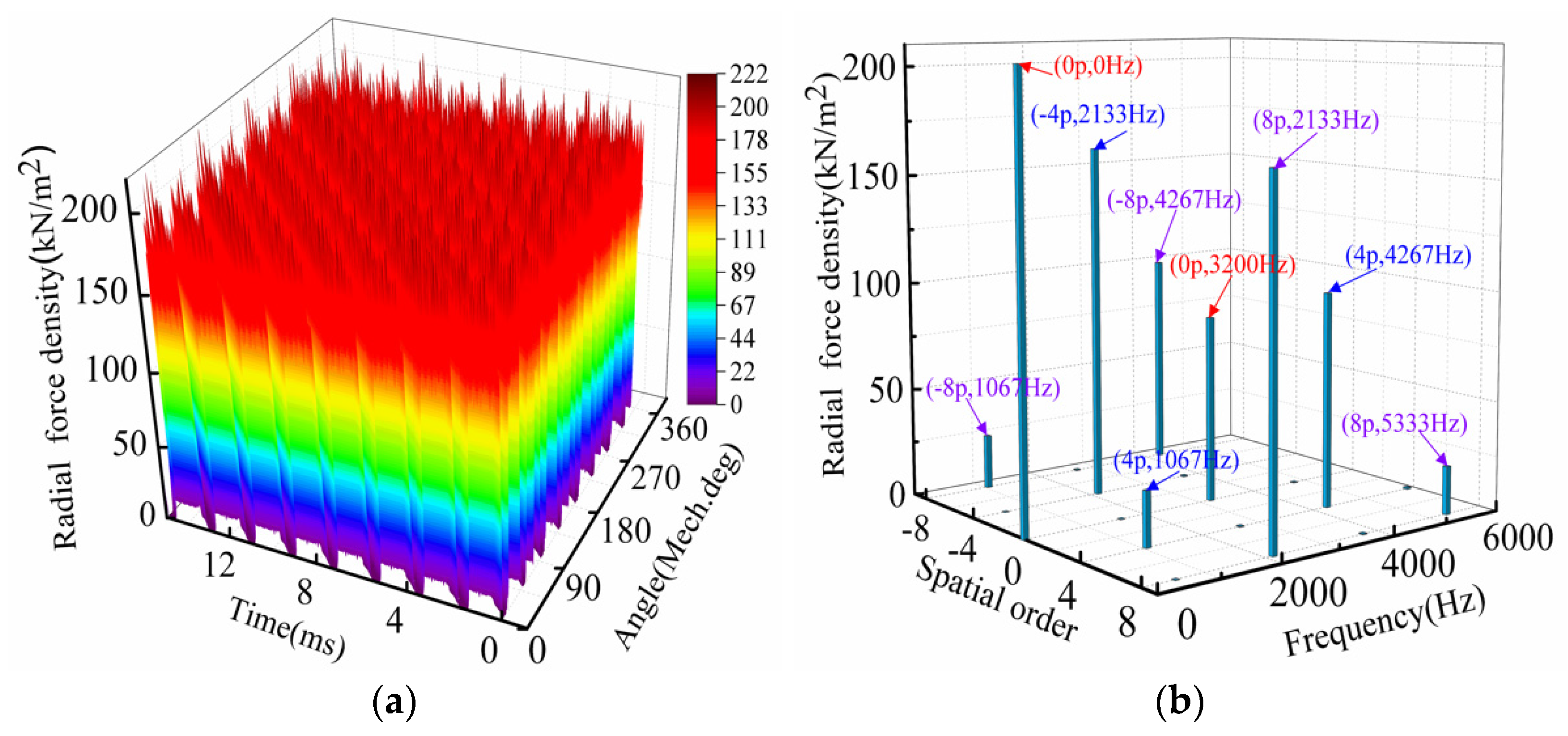
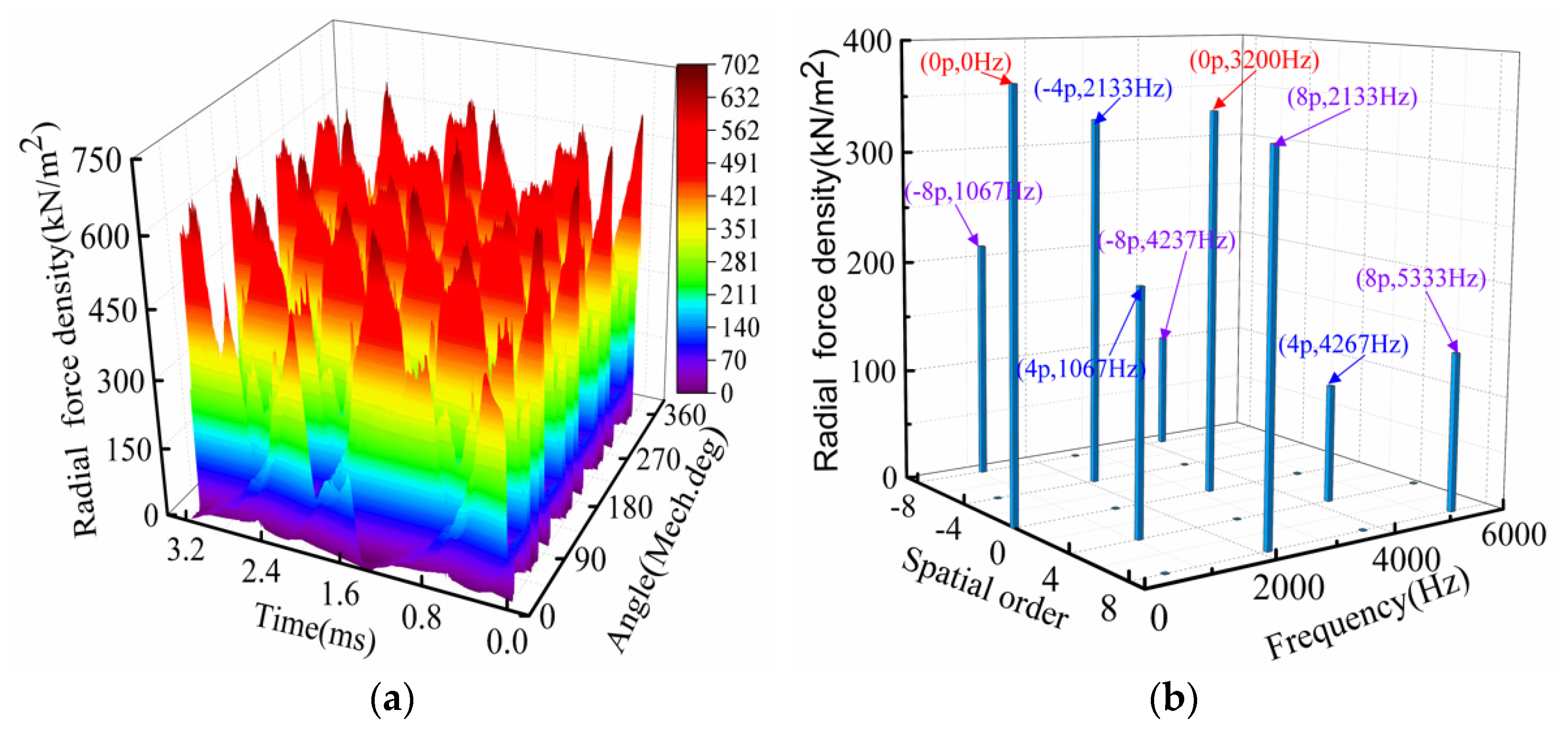
4.1. Radial Electromagnetic Force Density of PMSM

Figure 2 shows the spatial harmonic field of the radial electromagnetic force of the zero-phase stator teeth at the rated speed of the motor.
Ignoring the influence of the higher harmonics of the stator and the rotor, the first 13 harmonics of the magnetic potential of the rotor’s permanent magnet and the first 10 harmonics of the armature magnetic potential of the stator are substituted into the formula (11) of the radial electromagnetic force density derivation to obtain the no-load and load electromagnetic force density and the calculation error, as shown in Figure 3 and Figure 4, and Table 6 and Table 7, respectively. Due to the influence of the armature magnetic field of the rated load, it is obvious that the value of the electromagnetic force density under load is greater than that under no load. Because the influences of the magnetic potential and the high-order harmonics of the magnetic conductivity are ignored by the analytical method, the accuracy of the analytical calculation method (ACM) is lower than that of the finite element method (FEM).

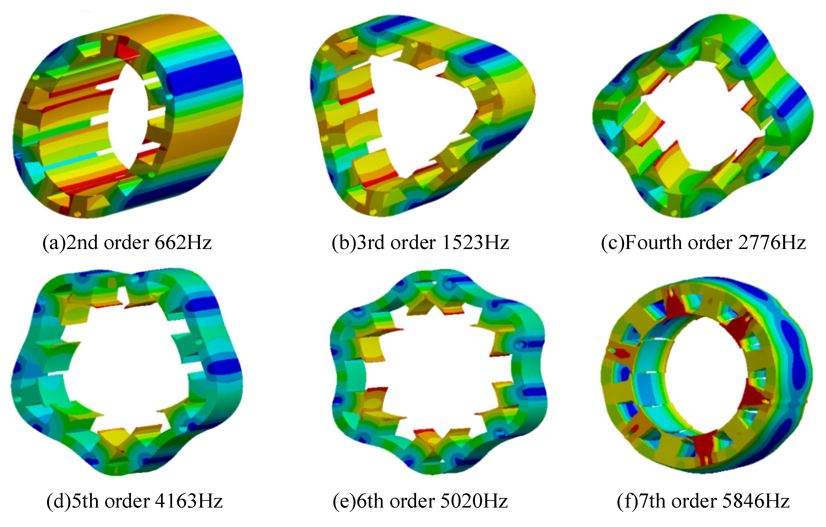
4.2. Modal Analysis of Motor Stator

When the radial electromagnetic force frequency of the motor and the inherent frequency of the vibration mode of the motor are close or coincident, it will cause a large resonance and produce a very obvious vibration noise. To avoid this resonance phenomenon, it is necessary to analyze and calculate the natural frequency of the motor stator. The new FeCo-based B800 and silicon steel sheet DW310_35 are used as the stator materials. The material performance parameters are shown in Table 8. Using the structure field simulation model, the vibration modes and natural frequencies of the motor stator are calculated as shown in Figure 5.
Based on the previous theoretical analysis of the radial electromagnetic force order and the frequency of the motor, the effective modes of the electromagnetic vibration noise of the 12-slot, 8-pole, permanent-magnet synchronous motor are shown in Table 9.
The fundamental frequencies of the motor are f = 266.7 Hz, 2f = 533.4 Hz, 4f = 1066.7 Hz, 8f = 2133.3 Hz, etc. The radial electromagnetic force frequency in Table 9 is far from the stator natural frequency in Figure 5, so the motor will not have a large resonance, nor will it have resonance.

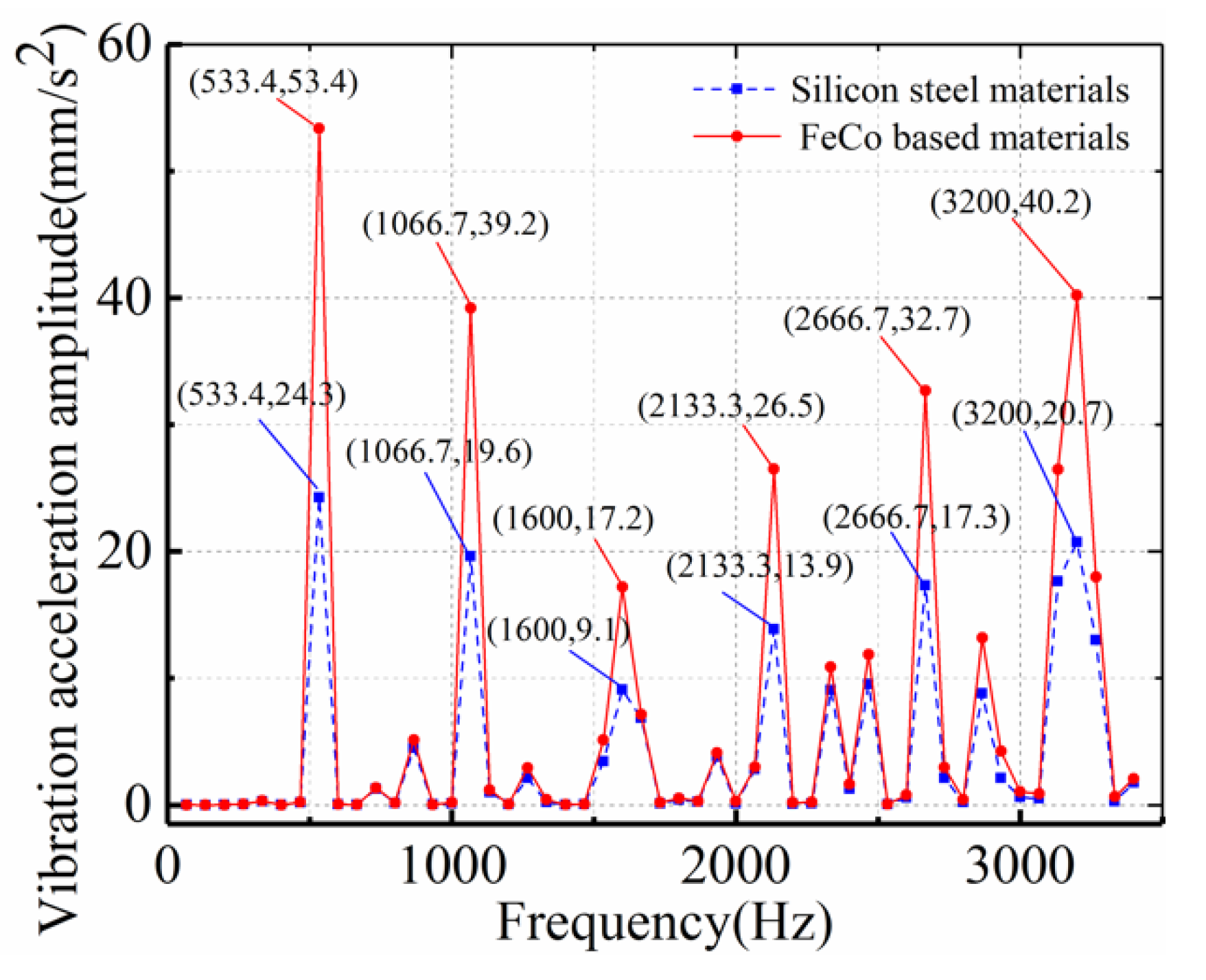
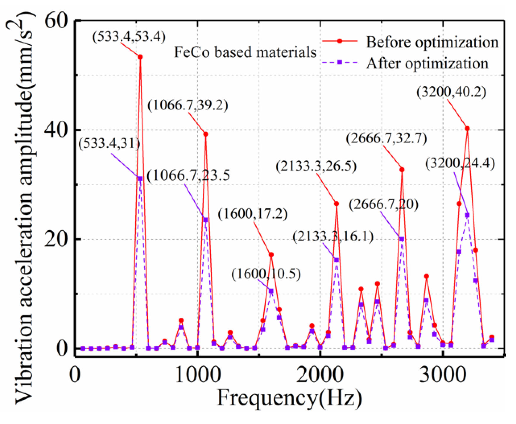
4.3. Vibration Analysis of PMSM

The vibration harmonic response models of two kinds of stator material motors are established, and the 3D finite element vibration harmonic response analysis is carried out. By loading the radial electromagnetic force on the corresponding motor stator teeth as the excitation source for the vibration analysis and by setting the boundary conditions of the solver and the motor vibration, the harmonic response can be solved. The result is the deformation of the stator caused by the radial electromagnetic force at different frequencies. A finite element calculation model for the coupling of the electromagnetic field and the structure field of the motor is established, and the vibration and noise spectrum of the motor in the range of 1000 r/min–8000 r/min multi-speed is calculated.
Comparing the performance of the two stator materials, B800 and DW310_35, it is necessary to ensure that the radial electromagnetic force loaded by them remains unchanged. After selecting a point on the inner surface of the motor housing, the average value of each node on the surface of the stator teeth is analyzed. The accelerations of the stator vibrations of the FeCo-based motor and the silicon steel motor are calculated. The acceleration spectrum curve of the motor vibration is obtained and shown in Figure 6. In Figure 6, it can be seen that the vibration acceleration of the new FeCo-based B800 motor is significantly greater than that of the silicon steel motor. This is mainly due to the fact that the elastic modulus of the new FeCo-based B800 material is much smaller than that of the silicon steel sheet, which results in the performance of suppressing electromagnetic vibration not being as good as that of the silicon steel sheet.
The motor vibration accelerations of the FeCo-based B800 and silicon steel DW310_35 stator materials are higher at 533.4 Hz, 1066.7 Hz, 1600 Hz, 2133.3 Hz, 2666.7 Hz, and 3200 Hz, which correspond to 2f, 4f, 6f, 8f, 10f, and 12f, respectively. From the Formulas (12)–(14) derived earlier, it is known that the radial electromagnetic force amplitude of the motor at these frequency points is relatively large, so the vibration is obvious. The optimized rotor structure is shown in Figure 1, and it can be seen in Figure 7 that the acceleration amplitude of the FeCo-based permanent-magnet motor after optimization significantly decreases as a whole. Its maximum value decreases from 53.4 before optimization to 31, which decreases by 41.95%. The goal is to ensure that the electromagnetic performance of the FeCo-based permanent-magnet motor cannot be changed. The reason why points with frequencies higher than 3200 Hz are not analyzed is that in these high frequencies, the radial electromagnetic force of the FeCo-based B800 stator material motor is already very small, so these frequency points do not cause a large vibration acceleration.

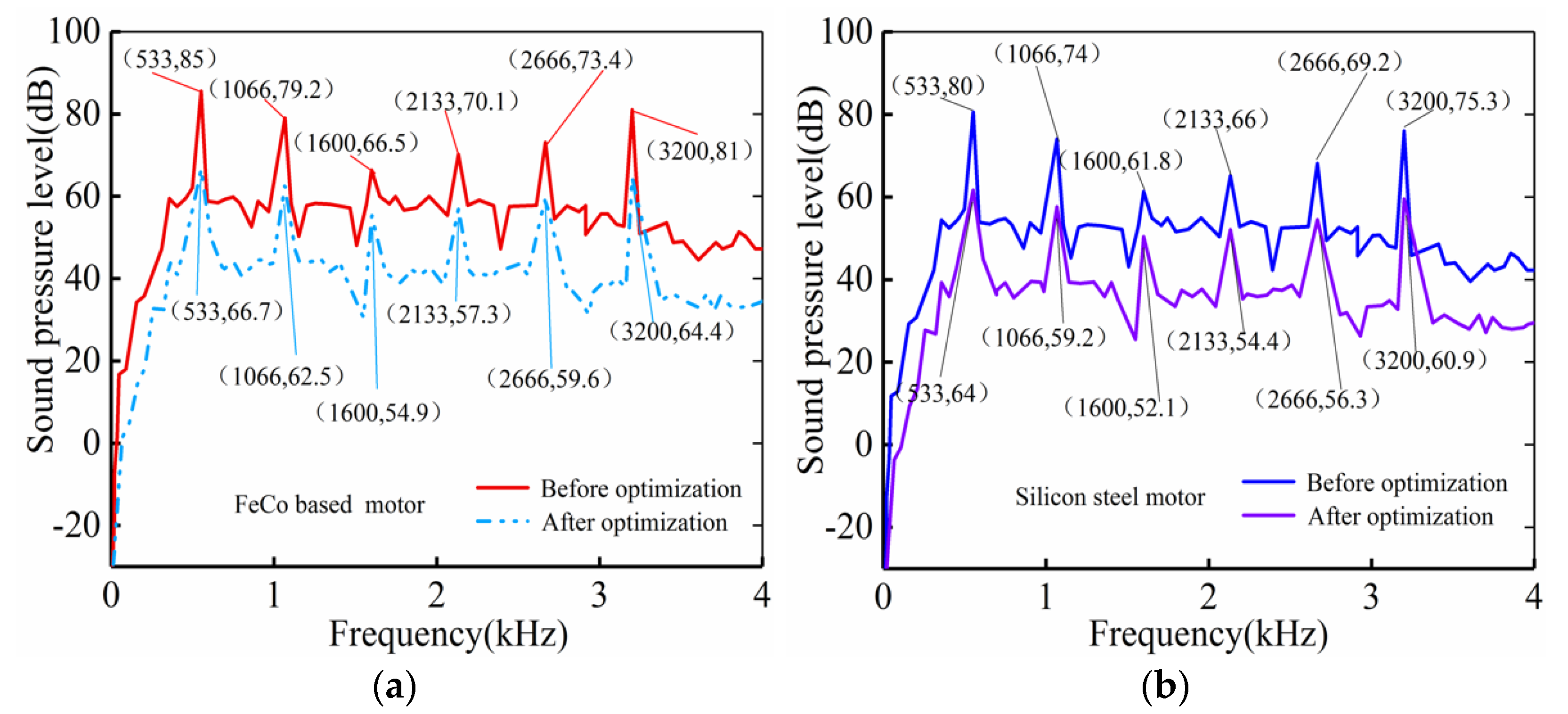
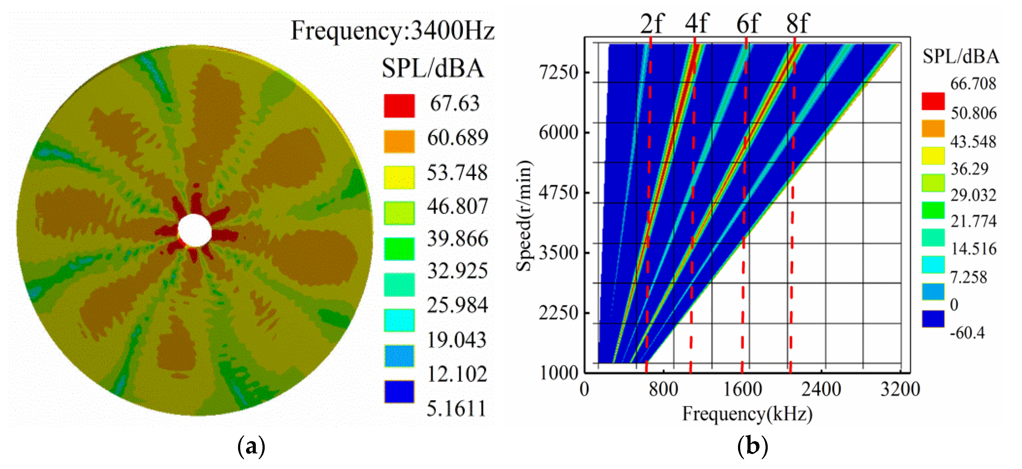
4.4. Noise Analysis of PMSM

Based on the simulation analysis of the vibration and harmonic response of two materials, FeCo-based B800 and silicon steel DW310_35, the electromagnetic noise of the motor is simulated. Electromagnetic noise is the noise caused by structural vibration resulting from electromagnetic force. The electromagnetic noise at the rated speed is simulated by spherical radiation, and the noise radiation surface is used to calculate the fluid, that is, the sound transmission medium, as air. The spectrum of the sound pressure level of the electromagnetic noise at a point on the inner surface of the motor housing can be observed by simulation, and coordinate points the same as those of the vibration solution are selected for analysis. The optimized rotator is used to compare the sound pressure level (SPL) of the original motor, as shown in Figure 8.
The noise spectrum distribution of the FeCo-based motor is obtained by establishing a simulation model of the acoustic coupled field of the magnetic field structure. Figure 9a presents the sound pressure level distribution of the FeCo-based motor in an air area of 1 m. It is obvious from the picture that sound appears in an umbrella-shaped distribution in the air; the closer to the motor, the greater the sound pressure level and the greater the noise, and the radial sound radiation diffuses outward.
Figure 9b shows a waterfall diagram of the full-speed noise spectrum of the motor within 8000 rpm. The high-noise areas are mainly concentrated in the zero-order, fourth-order, eighth-order modes and high-speed states. This confirms the high-noise areas deduced by the previous theory. When the FeCo-based permanent-magnet motor is in a high-speed, low-magnetic state, the air-gap harmonics caused by the low-magnetic field will increase, and a large vibration noise will also be generated.

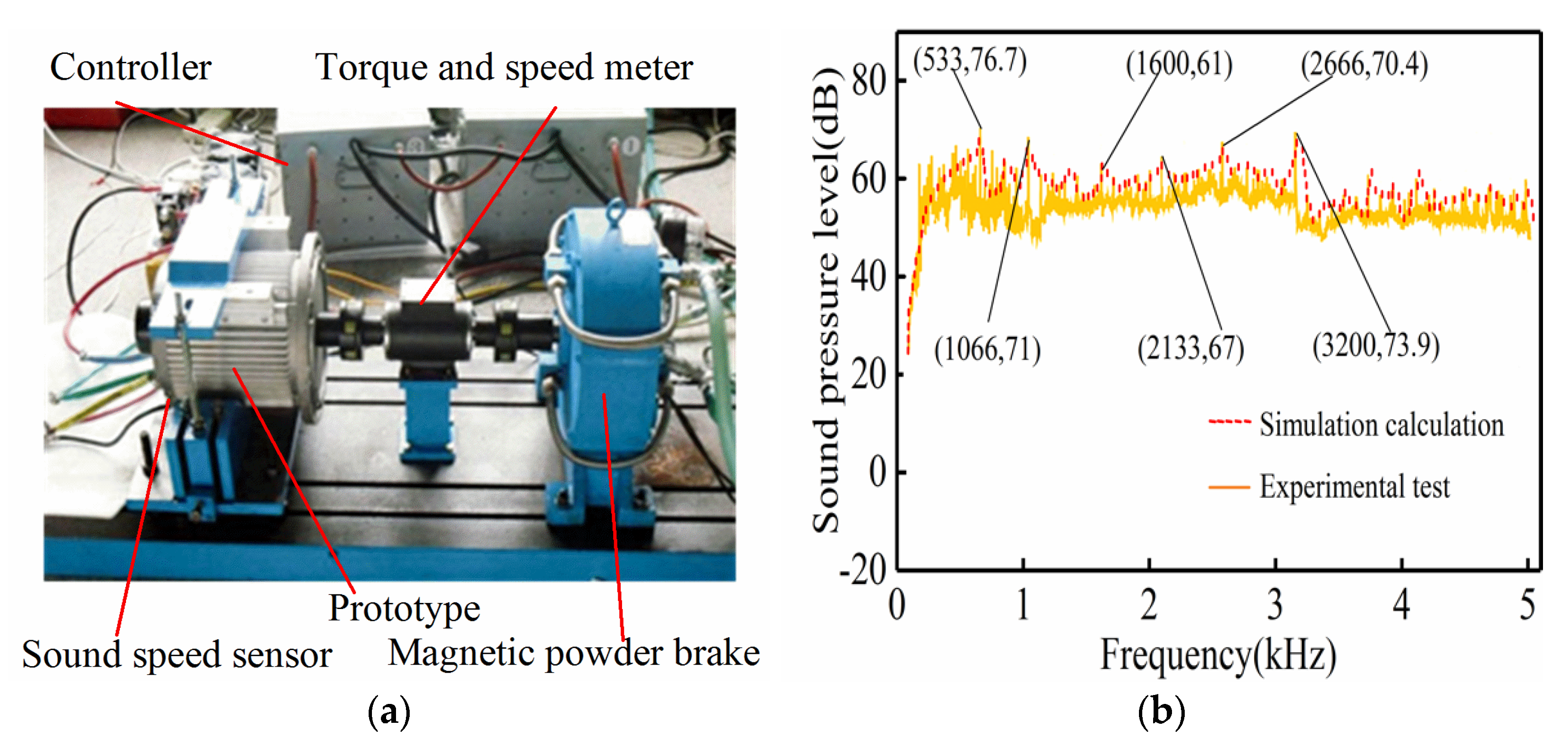
5. Verification of Prototype Experiment

In order to verify the accuracy of the derivation and calculation of the electromagnetic radial electromagnetic force and the multi-physical field simulation method of vibration and noise, the results of the multi-physical field coupling simulation are verified by conducting a prototype experiment. This paper studies the electromagnetic vibration noise of a permanent-magnet motor. Therefore, the noise of the motor at a speed of 4000 r/min is measured, as shown in Figure 10a. A noise test diagram of a prototype of the FeCo-based permanent-magnet motor after structural optimization is given. The noise measurement of the FeCo-based motors is carried out using a PU probe. Limited by the experimental conditions and in order to reduce the interference of background noise as much as possible, shock pad rubber is specifically added at a fixed position on the motor bottom. The experiment is carried out in the evening with low background noise.
In the vibration noise test, a sound speed sensor is placed at a point on the inner surface of the motor housing (the coordinates are of the same point as those in the previous simulation). Figure 10b presents the measured SPL spectral data of the FeCo-based material motor; it can be seen that there is a big difference between the actual measurement and the simulation results. The main reason for this is that the simulation calculation only considers the electromagnetic noise and makes the approximate simplification. In addition to the electromagnetic noise, the motor itself also has mechanical noise, aerodynamic noise, and so on, although there is a certain difference in the actual measurement of the motor vibration noise. However, the overall change trend of the electromagnetic noise in the simulation analysis is consistent with the actual measurement. In particular, at frequency points with a high noise value, the maximum SPL value appears at 533 Hz, which is consistent with the results of the simulation analysis. Therefore, the simulation results can predict the vibration noise of the motor very well.

6. Conclusions

In this paper, a new FeCo-based permanent-magnet motor with 8 poles, 12 slots, and 30 kW is studied by using the coupling analysis method of the electromagnetic field, structure field, and sound field. The radial electromagnetic force and vibration noise characteristics under no load and load are analyzed in detail. A new FeCo-based material is proposed for the stator of the motor. A numerical analysis and a calculation of the two material schemes are carried out. The rationality and validity of the computational simulation and theoretical derivation are verified by conducting prototype experiments, and the following conclusions can be drawn:
(1) The electromagnetic vibration noise of the new FeCo-based motor is not only related to the radial electromagnetic force of the motor but also to the elastic modulus of the stator material. The radial air-gap magnetic density of the motor determines the radial electromagnetic force, and the elastic modulus of the stator material determines the ability to suppress electromagnetic vibration.
(2) The low-order frequencies of the new FeCo-based motor, namely, 2f = 533.4 Hz, 4f = 1066.7 Hz, 6f = 1600 Hz, 8f = 2133.3 Hz, 10f = 2666 Hz, and 12f = 3200 Hz, are obtained by simulation, and they are in agreement with the results derived from the analytical formula.
(3) The vibration acceleration and noise of both the silicon steel motor and the new FeCo-based motor are greatly reduced after optimization. The maximum vibration acceleration of the FeCo-based motor decreases from 53.4 mm/s2 before optimization to 31 mm/s2, which is a reduction of 41.95%; the average value of the electromagnetic noise of the sound pressure level decreases from 60.5 dB to 48.3 dB, which is a decrease of 20.2%; the maximum value of the vibration acceleration of the silicon steel motor decreases from 24.3 mm/s2 before optimization to 11.9 mm/s2, which is a reduction of 51.1%; and the average value of the electromagnetic noise of the sound pressure level decreases from 55.7 dB to 39.3 dB, which is a decrease of 29.4%. The correctness of the multi-physical field coupling simulation is verified by the motor experiment of the new FeCo-based material.

Author Contributions

Conceptualization, B.G.; software, P.H.; formal analysis, PH. and B.P.; data curation, P.H.; writing—original draft preparation, P.H.; writing—review and editing, P.H. and B.G.; supervision, B.G.; funding acquisition, D.T. and Y.W. All authors have read and agreed to the published version of the manuscript.

Funding

The China National Defense Basic Research Project: JCKY2018412C006.

Institutional Review Board Statement

The study did not involve humans or animals.

Informed Consent Statement

Not applicable.

Data Availability Statement

The study did not report any data.

Conflicts of Interest

The authors declare no conflict of interest.

References

  1. Souri, M.; Moradi Kashkooli, F.; Soltani, M.; Raahemifar, K. Effect of Upstream Side Flow of Wind Turbine on Aerodynamic Noise: Simulation Using Open-Loop Vibration in the Rod in Rod-Airfoil Configuration. Energies 2021, 14, 1170. [Google Scholar] [CrossRef]
  2. Zhang, Z.; Yaman, S.; Salameh, M.; Singh, S.; Chen, C.; Krishnamurthy, M. Effectiveness of Power Electronic Controllers in Mitigating Acoustic Noise and Vibration in High-Rotor Pole SRMs. Energies 2021, 14, 702. [Google Scholar] [CrossRef]
  3. Li, X.; Liu, C.; Mei, B.; Wei, S.; Xia, N. Vibration and noise sources analysis of IPMSM for electric vehicles in a wide-speed range. Proc. CSEE 2018, 38, 5219–5227. [Google Scholar]
  4. Jafarboland, M.; Farahabadi, H.B. Optimum design of the stator parameters for noise and vibration reduction in BLDC motor. IET Elect. Power Appl. 2018, 12, 1297–1305. [Google Scholar] [CrossRef]
  5. Kim, H.-S.; Kwon, B.-I. Optimal design of motor shape and magnetization direction to obtain vibration reduction and average torque improvement in IPM BLDC motor. IET Elect. Power Appl. 2017, 11, 378–385. [Google Scholar] [CrossRef]
  6. Lin, F.; Zuo, S.G.; Wu, X.D. Electromagnetic vibration and noise analysis of permanent magnet synchronous motor with different slot-pole combinations. IET Electr. Power Appl. 2016, 10, 900–908. [Google Scholar] [CrossRef]
  7. Deng, W.; Zuo, S. Analytical Modeling of the Electromagnetic Vibration and Noise for an External-Rotor Axial-Flux in-Wheel Motor. IEEE Trans. Ind. Electron. 2017, 65, 1991–2000. [Google Scholar] [CrossRef]
  8. Li, Z.; Brindak, Z.; Lei, Z. Modeling of an Electromagnetic Vibration Energy Harvester with Motion Magnification. In Proceedings of the ASME 2011 International Mechanical Engineering Congress and Exposition, Denver, CO, USA, 11–17 November 2011. [Google Scholar]
  9. Ting, D.; Ruiqing, W.; Jicheng, Z.; Kun, L. Influence of auxiliary slot on electromagnetic vibration in PMSM with similar slot and pole number. In Proceedings of the 2017 20th International Conference on Electrical Machines and Systems (ICEMS), Sydney, NSW, Australia, 11–14 August 2017; pp. 1–6. [Google Scholar]
  10. Zhou, G.Y.; Shen, J.X. Rotor Notching for Electromagnetic Noise Reduction of Induction Motors. IEEE Trans. Ind. Appl. 2017, 10, 10–13. [Google Scholar] [CrossRef]
  11. Hong, J.; Wang, S.; Sun, Y.; Cao, H. An effective method with copper ring for vibration reduction in permanent magnet brush DC motors. IEEE Trans. Magn. 2018, 54, 8105–8108. [Google Scholar] [CrossRef]
  12. Zou, J.; Lan, H.; Xu, Y.; Zhao, B. Analysis of global and local force harmonics and their effects on vibration in permanent magnet synchronous machines. IEEE Trans. Energy Convers. 2017, 32, 1523–1532. [Google Scholar] [CrossRef]
  13. Wu, S.L.; Zuo, S.G.; Zhang, Y.D. Optimization for electromagnetic noise reduction in claw pole alternator by rotor claw chamfering. IEEE Trans. Ind. Electron. 2018, 65, 9325–9335. [Google Scholar] [CrossRef]
  14. Gao, L.; Zheng, H.; Zeng, L.; Pei, R. Evaluation Method of Noise and Vibration used in Permanent Magnet Synchronous Motor in Electric Vehicle. In Proceedings of the 2019 IEEE Transportation Electrification Conference and Expo (ITEC), Detroit, MI, USA, 19–21 June 2019; pp. 1–4. [Google Scholar]
  15. Wang, S.M.; Hong, J.F.; Sun, Y.G.; Cao, H. Analysis and reduction of electromagnetic vibration of PM brush DC motors. IEEE Trans. Ind. Appl. 2019, 55, 4605–4612. [Google Scholar] [CrossRef]
  16. Sun, T.; Kim, J.M.; Lee, G.H.; Hong, J.P.; Choi, M.R. Effect of Pole and Slot Combination on Noise and Vibration in Permanent Magnet Synchronous Motor. IEEE Trans. Magn. 2011, 47, 1038–1041. [Google Scholar] [CrossRef]
  17. Huang, S.; Aydin, M.; Lipo, T.A. Electromagnetic vibration and noise assessment for surface mounted PM machines. In Proceedings of the Power Engineering Society Summer Meeting, Vancouver, BC, Canada, 15–19 July 2001. [Google Scholar]
  18. Jung, J.W.; Lee, S.H.; Lee, G.H.; Hong, J.P.; Lee, D.H.; Kim, K.N. Reduction Design of Vibration and Noise in IPMSM Type Integrated Starter and Generator for HEV. IEEE Trans. Magn. 2010, 46, 2454–2457. [Google Scholar] [CrossRef]
  19. Lin, F.; Zuo, S.; Deng, W.; Wu, S. Modeling and analysis of electromagnetic force, vibration and noise in permanent magnet synchronous motor considering current harmonics. IEEE Trans. Ind. Electron. 2016, 63, 7455–7466. [Google Scholar] [CrossRef]
  20. Min, S.G.; Sarlioglu, B. Analytical solution of electromagnetic noise caused by radial force and torque variation in fractional-slot PM motors with all teeth wound. IEEE Transp. 2017, 23, 247–251. [Google Scholar]
  21. Zuo, S.; Lin, F.; Wu, X. Noise Analysis, Calculation, and Reduction of External Rotor Permanent-Magnet Synchronous Motor. IEEE Trans. Ind. Electron. 2015, 62, 6204–6212. [Google Scholar] [CrossRef]
  22. Valente, G.; Papini, L.; Formentini, A.; Gerada, C.; Zanchetta, P. Radial force control of multi-sector permanent-magnet machines for vibration suppression. IEEE Trans. 2018, 65, 5395–5405. [Google Scholar]
  23. Stuckmann, C. Noise & Vibration levels of modern electric motors. In Proceedings of the International Exhibition and Conference for Power Electronics, Intelligent Motion, Renewable Energy and Energy Management (PCIM Europe 2016), Nuremberg, Germany, 10–12 May 2016; pp. 4242–4247. [Google Scholar]
  24. Qiao, M.; Jiang, C.; Zhu, Y.; Li, G. Research on design method and electromagnetic vibration of six-phase fractional-slot concentrated winding PM motor suitable for ship propulsion. IEEE Access 2016, 4, 8535–8543. [Google Scholar] [CrossRef]
  25. Chai, F.; Li, Y.; Pei, Y.; Li, Z. Accurate modeling and modal analysis of stator system in permanent magnet synchronous motor with concentrated winding for vibration prediction. IET Electr. Power Appl. 2018, 12, 1225–1232. [Google Scholar] [CrossRef]
  26. Zuo, S.G.; Liu, X.X.; Yu, M.H.; Wu, X.; Zhang, G. Numerical prediction and analysis of electromagnetic vibration in permanent magnet synchronous motor. Trans. China Electrotech. Soc. 2017, 32, 159–167. [Google Scholar]
Figure 1. Finite element model of V rotor of PMSM.
Energies 15 03888 g001
Figure 2. Radial force density distribution of stator teeth.
Energies 15 03888 g002
Figure 3. No-load radial electromagnetic force density. (a) Force density distribution; (b) low-order radial force density component.
Energies 15 03888 g003
Figure 4. Load radial electromagnetic force density. (a) Force density distribution; (b) low-order radial force density component.
Energies 15 03888 g004
Figure 5. Modal shape of FeCo-based stator.
Energies 15 03888 g005
Figure 6. Comparison curve of vibration acceleration frequency spectrum of different materials.
Energies 15 03888 g006
Figure 7. Vibration acceleration spectrum contrast diagram of motor.
Energies 15 03888 g007
Figure 8. Contrast results of SPL frequency spectrum of FeCo-based motor. (a) FeCo-based motor; (b) silicon steel motor.
Energies 15 03888 g008
Figure 9. (a) SPL and noise distribution within 1 m of FeCo-based motor; (b) noise waterfall diagram of FeCo-based motor under load.
Energies 15 03888 g009
Figure 10. (a) Field test diagram of noise of FeCo-based motor; (b) comparison between SPL spectrum simulation and experimental test.
Energies 15 03888 g010
Table 1. Main parameters of permanent-magnet motor.
ParameterValueParameterValue
Rated power30 kWStator diameter210 mm
Rated voltage194 VAir-gap length1.6 mm
Rated current94 ARotor diameter150 mm
Rated speed4000 rpmPM thickness7.7 mm
Slot/pole12/8Core length175 mm
Table 2. The order and frequency of radial electromagnetic force.
Rotor Permanent
Magnetic Field
Stator Armature
Magnetic Field
PM Magnetic Field and Armature Reaction Magnetic Field
OrderFrequencyOrderFrequencyOrderFrequency
( μ 1 μ 2 ) p 0 ( μ 1 μ 2 ) f 0 ( ν 1 ν 2 ) p 0 0 ( μ ν ) p 0 ( ν 1 ) f 0
( μ 1 μ 2 ) p 0 ( μ 1 + μ 2 ) f 0 ( ν 1 + ν 2 ) p 0 2 f 0 ( μ + ν ) p 0 ( ν + 1 ) f 0
( μ 1 μ 2 ) p 0 ± 2 z 0 ( μ 1 μ 2 ) f 0 ( ν 1 ν 2 ) p 0 ± 2 z 0 0 ( μ ν ) p 0 ± 2 z 0 ( ν 1 ) f 0
( μ 1 + μ 2 ) p 0 ± 2 z 0 ( μ 1 + μ 2 ) f 0 ( ν 1 + ν 2 ) p 0 ± 2 z 0 2 f 0 ( μ + ν ) p 0 ± 2 z 0 ( ν + 1 ) f 0
( μ 1 μ 2 ) p 0 ± z 0 ( μ 1 μ 2 ) f 0 ( ν 1 ν 2 ) p 0 ± z 0 0 ( μ ν ) p 0 ± 2 z 0 ( ν 1 ) f 0
( μ 1 + μ 2 ) p 0 ± z 0 ( μ 1 + μ 2 ) f 0 ( ν 1 + ν 2 ) p 0 ± z 0 2 f 0 ( μ + ν ) p 0 ± 2 z 0 ( ν + 1 ) f 0
Table 3. The permanent magnetic field alone generates radial electromagnetic force.
Harmonic
Order
Order/Frequency Multiplier
μ2
μ1135791113
10/0
2/2
2/2
4/4
4/4
6/6
6/6
8/8
8/8
10/10
10/10
12/12
12/12
14/14
3 0/0
6/6
2/2
8/8
4/4
10/10
6/6
12/12
8/8
14/14
10/10
16/16
5 0/0
10/10
2/2
12/12
4/4
14/14
6/6
16/16
8/8
18/18
7 0/0
14/14
2/2
16/16
4/4
18/18
6/6
20/20
9 0/0
18/18
2/2
20/20
4/4
22/22
11 0/0
22/22
2/2
24/24
13 0/0
26/26
Table 4. The stator armature magnetic field alone generates radial electromagnetic force.
Harmonic
Order
Order/Frequency Multiplier
ν2
ν11−24−57−810
10/0
2/2
1/2
3/0
3/0
5/2
4/2
6/0
6/0
8/2
7/2
9/0
9/0
11/2
−2 0/0
4/2
2/2
6/0
3/0
7/2
5/2
9/0
6/0
10/2
8/2
12/0
4 0/0
8/2
1/2
9/0
3/0
11/2
4/2
12/0
6/0
14/2
−5 0/0
10/2
2/2
12/0
3/0
13/2
5/2
15/0
7 0/0
14/2
1/2
15/0
3/0
17/2
−8 0/0
16/2
2/2
18/0
10 0/0
20/2
Table 5. PM field and stator magnetic field produce radial electromagnetic force.
Harmonic
Order
Order/Frequency Multiplier
ν
μ1−24−57−810
10/0
2/2
1/2
3/0
3/0
5/2
4/2
6/0
6/0
8/2
7/2
9/0
9/0
11/2
32/2
4/4
1/4
5/2
1/2
7/4
2/4
8/2
4/2
10/4
5/4
11/2
7/2
13/4
54/4
6/6
3/6
7/4
1/4
9/6
0/6
10/4
2/4
12/6
3/6
13/4
5/4
15/6
76/6
8/8
5/8
9/6
3/6
11/8
2/8
12/6
0/6
14/8
1/8
15/6
3/6
17/8
98/8
10/10
7/10
11/8
5/8
13/10
4/10
14/8
2/8
16/10
1/10
17/8
1/8
19/10
1110/10
12/12
9/12
13/10
7/10
15/12
6/12
16/10
4/10
18/12
3/12
19/10
1/10
21/12
1312/12
14/14
11/14
15/12
9/12
17/14
8/14
18/12
6/12
20/14
5/14
21/12
3/12
23/14
Table 6. Main low-order no-load radial force density.
Low Order
(Order/Frequency)
0p/0f2p/2f4p/4f6p/6f8p/8f10p/10f12p/12f
ACM (kN/m2)203.50491.79676.54256.82131.46721.43816.819
FEM (kN/m2)208.91593.64178.36057.94532.08322.05617.256
Error/%−2.59−1.97−3.48−1.94−3.19−2.58−2.53
Table 7. Radial force density of main low order rated load.
Low Order
(Order/Frequency)
0p/0f2p/2f4p/4f6p/6f8p/8f10p/10f12p/12f
ACM (kN/m2)459.541224.648170.175123.81292.49267.06448.672
FEM (kN/m2)473.495230.139176.313127.81995.53769.57850.214
Error/%−2.95−2.38−3.48−3.13−3.19−3.61−3.07
Table 8. Stator material performance parameters.
ParameterFeCo-Based B800DW310_35
Saturation magnetic induction (T)2.462.03
Magnetostriction (×10−6)60
Density (kg/m3)82007650
Curie temperature (°C)980746
Resistivity (μΩ·m)0.40.45
Tensile strength (MPa)1340343
Elastic modulus (GPa)128206
Coercivity (A·m−1)≤128<30
Lamination coefficient0.880.95
Table 9. Frequency distribution of low-order radial force harmonics of 8-pole, 12-slot, permanent-magnet motor.
Spatial OrderFrequency Distribution
0…, −18f, −12f, −6f, 0f, 6f, 12f, 18f, …
4…, −14f, −8f, −2f, 4f, 10f, 16f, 22f, …
8…, −10f, −4f, 2f, 8f, 14f, 20f, 26f, …
Publisher’s Note: MDPI stays neutral with regard to jurisdictional claims in published maps and institutional affiliations.

