Article

Optical Wireless Power Transmission Using a GaInP Power Converter Cell under High-Power 635 nm Laser Irradiation of 53.5 W/cm2

Department of Advanced Materials Science and Engineering, Chiba Institute of Technology, 2-17-1 Tsudanuma, Narashino 275-0016, Japan
*
Author to whom correspondence should be addressed.
Energies 2022, 15(10), 3690; https://doi.org/10.3390/en15103690
Submission received: 14 April 2022 / Revised: 3 May 2022 / Accepted: 10 May 2022 / Published: 18 May 2022

Abstract

:
Optical wireless power transmission (OWPT) system is a technology that supplies energy from remote locations, having some features such as long-distance transmission, high directivity, and no electromagnetic noise interference. This study investigated the optical transmission efficiency and photoelectric conversion efficiency with a transmission distance of 10 m using GaInP power converter cells with a small area of 2.40 × 2.40 mm2 and a 635 nm high-power laser over 50 W/cm2. As a result, we achieved a photoelectric conversion efficiency of 44.7% under 6.7 W/cm2 (0.14 W) and 37.2% under 53.5 W/cm2 (1.1 W) irradiation. These results suggested that W-class optical wireless power transmission could be realized by expanding the converter cell area. Additionally, it was found that the reductions of the divergence angle of the laser and the heat generation of the power converter cell were critical issues for further lengthening the distance and increasing the power.

1. Introduction

With the evolution of IoT, a new revolution in wireless power transmission (WPT) is expected to occur along with wireless information and communication. WPT is a technology for remotely transmitting energy from a power source to electrical equipment. There are two types of WPT: short-distance and long-distance [1]. An example of a currently popular short-distance WPT is the electromagnetic induction method used in a narrow range of a few centimeters or less. On the other hand, long-distance WPT has two ways: microwave and optical light. The microwave method incorporates electromagnetic waves from 10 cm to 0.1 mm (about 0.1 GHz to 100 GHz) [2]. However, high-power electromagnetic waves have the problem of causing electromagnetic interference.
Therefore, among long-distance WPT methods, optical wireless power transmission (OWPT) is attracting attention [3,4,5,6,7]. The optical light from a laser or LED is transmitted through space, and the light power is converted into electricity at a remote photo receiver. OWPT system has the advantage that an optical beam with a narrow divergence angle could extend the transmission distance. In addition, this method has the features that a compact system and high-power transmission are possible. Table 1 shows the characteristics of representative OWPT systems in various wavelength ranges.
Most of the studies on the OWPT system have used near-infrared light to suppress the light absorption and the scattering in the air [8,9,10]. However, it is challenging to avoid laser light when used in real spaces because near-infrared is invisible to humans. In a realistic space, visible light could be avoided by blinking. In this study, we demonstrate the OWPT system using visible light because visible light makes the hazardous area clear, allows safety measures, and facilitates system maintenance.
In visible wavelength range, Steinsiek demonstrated the OWPT system with a GaInP solar cell under 4.3 W high-power 532 nm laser irradiation of 0.27 W/cm2, which system had the 40% photoelectric conversion efficiency and the solar output power of 1.75 W [12]. Komuro reported that the GaInP power converter cell had a photoelectric conversion efficiency of 43.0% under 638 nm laser irradiation of 17 W/cm2 (0.3 W) [13].
We also reported the OWPT system with a distance of 120 m using a GaInP solar cell under a 609 nm laser of 60.8 mW (8.4 W/cm2), which had the 44.1% photoelectric conversion efficiency and the 40.5% system efficiency defined as an output power of a solar cell divided by a laser incident power [14]. Tai and Miyamoto demonstrated the Fly-eye Lens based underwater OWPT system with Si and GaAs converter cells irradiated with 450 nm lasers [15]. They reported the photoelectric conversion efficiency of the solar cells were 10.8% for Si and 19.1% for GaAs for 450 nm wavelength. The OWPT system with visible light is expected to be used in various applications. For example, it supplies power to moving vehicles such as automobiles and transport robots at distribution centers and supplies power to underwater probes due to its high transmittance in water [16].
In the OWPT system, it is essential to minimize a laser optical power transfer loss, reducing a beam divergence. A. Riza lab proposed and demonstrated the smart three dimensional (3D) beamforming optics which enabled controlling the Gaussian beam propagation and far-field illumination characteristics, leading to the low transfer loss [17,18,19]. In addition, for LED powered links, Riza lab demonstrated the energy efficient optical wireless link designs using smart 3D beamforming [20]. Zhao and Miyamoto et al. also has shown experimental progress based of 3D beamforming-based optical wireless optimized collimation links using a visible band 3-LED-array to produce 532 mW of electrical power over a 1 m distance with a 43% beam lensing system efficiency [21].
This study demonstrated a high-power 1 W class and a long-distance 10 m transmission using 635 nm laser light and GaInP solar cell, reducing the beam divergence by using a beam expander. As a result, we achieved a photoelectric conversion efficiency of 44.7% under 6.7 W/cm2 (0.14 W) and 37.2% under 53.5 W/cm2 (1.1 W) irradiation. The system efficiencies were obtained to be 41.4% for 6.7 W/cm2 irradiation and 34.1% for 53.5 W/cm2 irradiation, respectively.

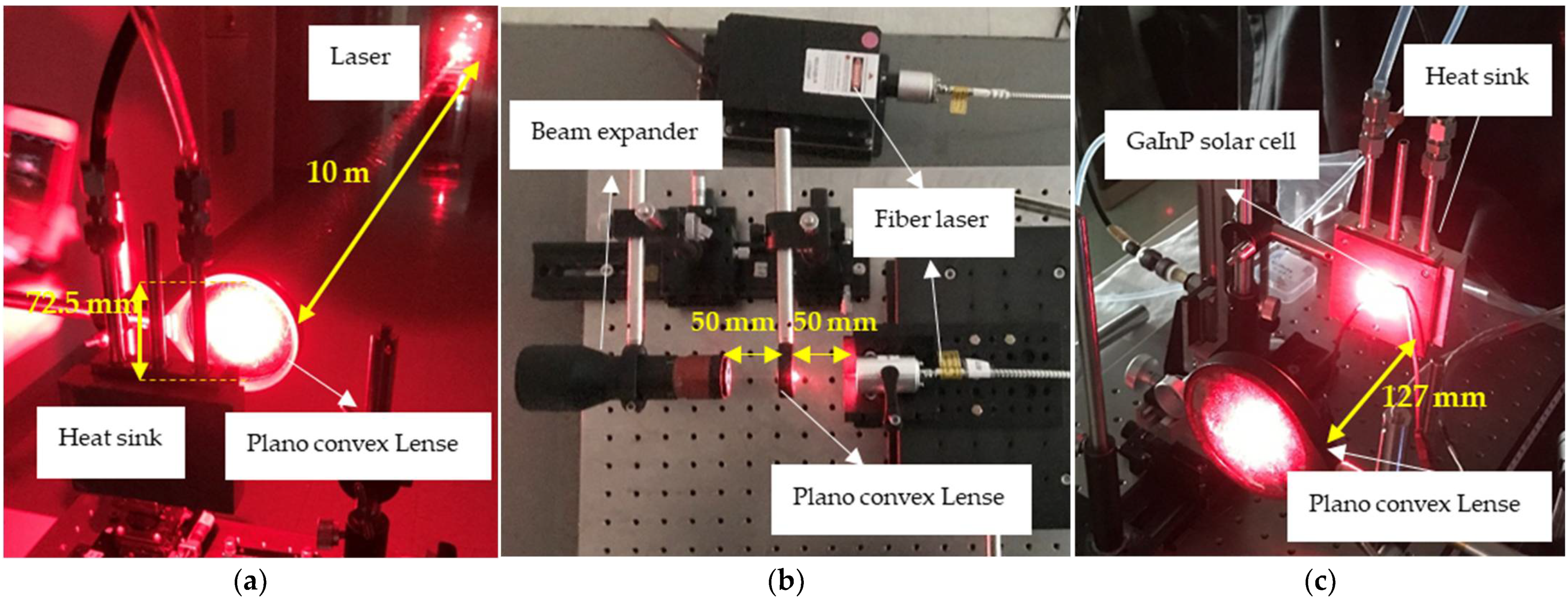
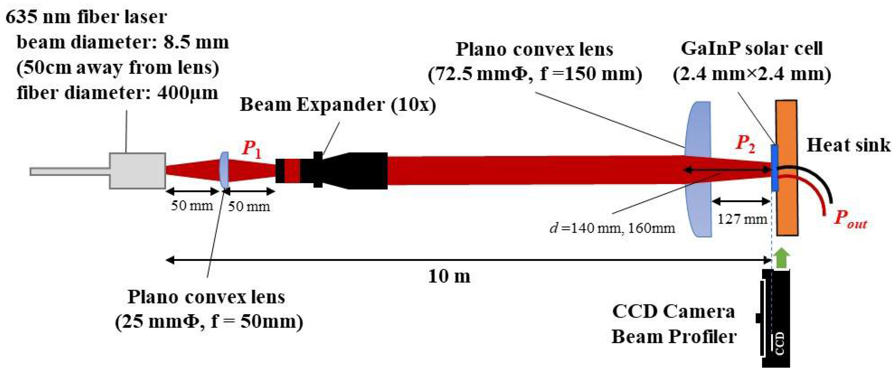
2. Materials and Methods
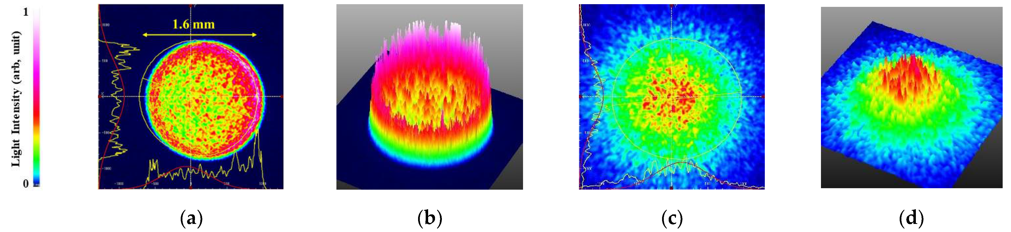
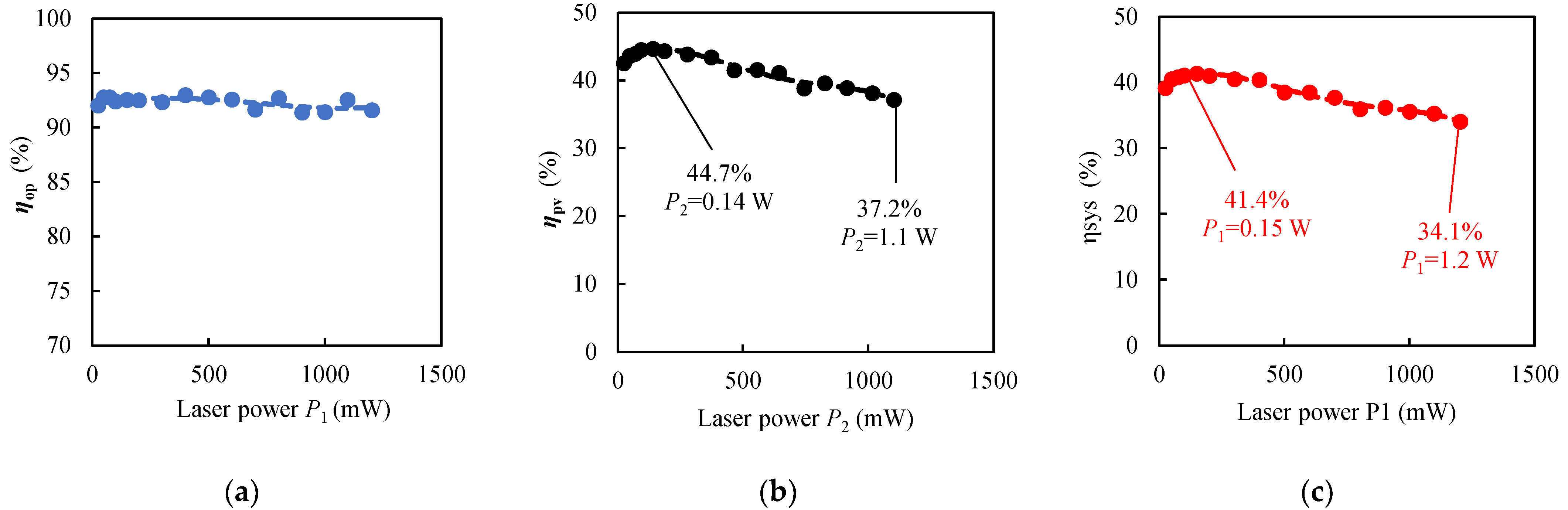
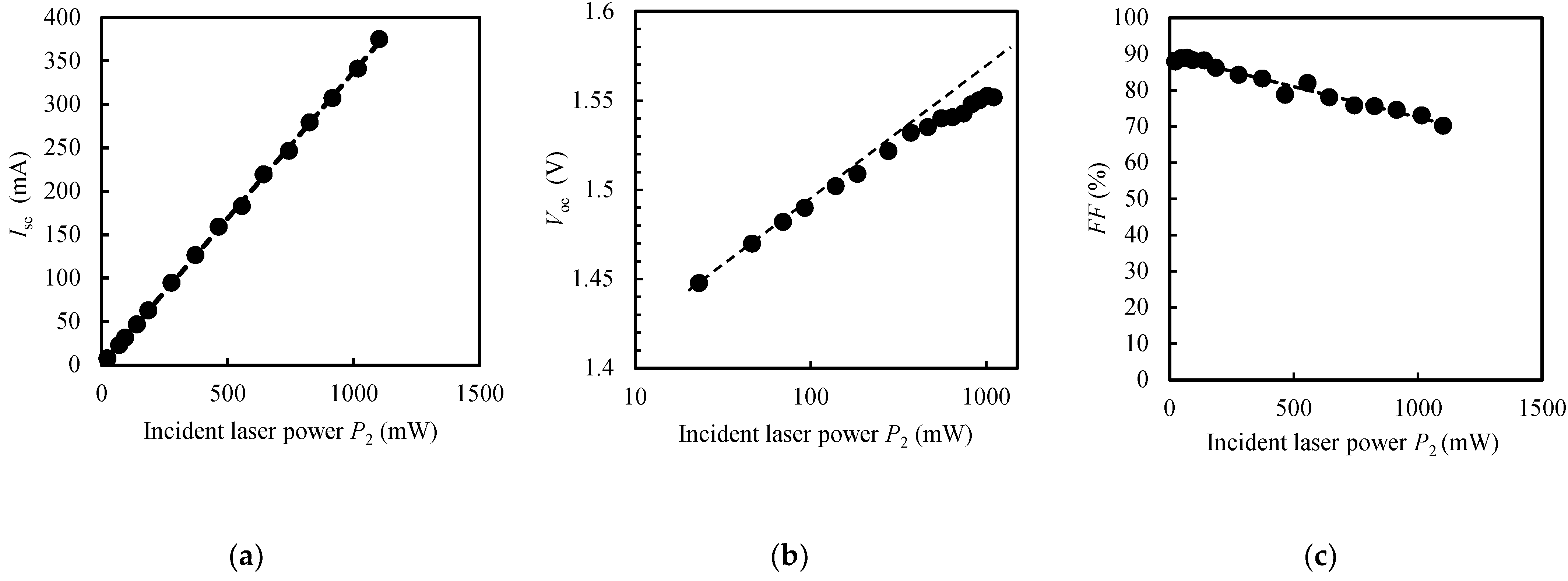
This study tested long-distance and high-power transmission in the visible wavelength range. In Figure 1, we demonstrated the transmission of 1.2 W laser power over 10 m and obtained a solar cell output power of 0.41 W and a system efficiency of 34.1%, which is defined as the maximum output power (Pout) of the converter cell divided by the laser output power (P1). Figure 1 and Figure 2 show the experimental configuration used for optical wireless power transmission. The transmission distance from the light source to the solar cell was set at 10 m, as shown in Figure 2a.
The light source is a 635 nm fiber laser that can output power up to 1.2 W with the beam divergence full angle of 14.7 mrad and about 5.0 mm beam diameter at the aperture. A 10× Beam Expander (GBE10-A, THOURLABS), was set up in this optical system to reduce the divergence angle, as shown in Figure 2b. This Beam Expander (BE) increased the diameter of the incident laser beam by 10 times and reduced the divergence angle by 1/10. As shown in Figure 2a, a plano-convex lens (Diameter = 25 mm, f = 50 mm) was placed 50 mm from the laser light source to direct the laser beam into the inlet of the BE (Diameter = 3.5 mm. The be was placed 50 mm from the previous plano-convex lens to minimize the incident beam diameter, as shown in Figure 2b.
GaInP solar cell with a light-receiving area of 2.40 × 2.40 mm2 was prepared. The solar cell was mounted on a copper heatsink, which temperature was kept constant by using a water-cooled circulation type chiller (2–3 L/min). The heatsink temperature was measured as 14 °C, close to the temperature in the corridor without air conditioning on 24 February 2022. Plano-convex lens (Diameter = 72.5 mm, f = 150 mm) was set up in front of the solar cell, as shown in Figure 2a,c. The size of the beam incident on this convex lens was 70 mm. The distance between this focusing lens and the solar cell was adjusted to 127 mm so that the largest beam was irradiated on the receiving area of the solar cell.
The intensity distributions of the 67.2 mW laser light at the positions (d = 140 mm, 160 mm) described in Figure 1 were measured by the CCD Camera Beam Profiler (BC106N-VIS/M, THOURLABS), as shown in Figure 3a,b. The yellow curves show the measured profiles, while the red lines show the Gaussian fitting curves. These profiles had the jagged roughness due to the fiber laser source. The laser intensity distribution in front of the lens focus exhibited near-uniform due to the aberration of the lens. On the other hand, the intensity distribution at the position farther than the focal length was non-uniform, as shown in Figure 3c,d. Kurooka et al. reported that homogenization of laser intensity distribution improved the photoelectric conversion efficiency of the solar cell [22]. They also reported that the non-uniform laser irradiation with a Gaussian profile generated many carriers in the center region of the irradiated cell surface, leading to the decrease in conversion efficiency due to the Joule heating [17]. Therefore, the uniform laser irradiation could suppress the efficiency decrease under high-power irradiation.
As described in Figure 1, P1 was measured by the photodiode power sensor (S130C, THOULABS; Uncertainty = ±3%) as the laser power between the BE and the plano-convex lens, and P2 was measured by the same power sensor as the incident power to the solar cell. Pout was measured as the output power of the solar cells by the source measure unit (B2901A, KEYSIGHT), which possess 100 fA and 100 nV measurement resolution and 1 pA and 1 μV sourcing resolution. These values were measured as the highest values obtained by adjusting the power sensor and the converter cell positions. Optical reaching rate ηop, photoelectric conversion efficiency ηpv, and system efficiency ηsys were defined as P2/ P1, Pout/P2, and Pout/P1, respectively. These values were evaluated under the relatively uniform irradiation, as shown in Figure 3a,b.

3. Results

In Figure 4a, the optical reaching rate ηop exhibited 91~93%, slightly decreasing as the laser power increased. The photoelectric conversion efficiencies were plotted as a function of the incident laser power P2, as shown in Figure 4b. We achieved ηpv of 37.2% when P2 was 1.1 W and the highest ηpv of 44.7% with P2 = 0.14 W. After the peak in Figure 4b, photo conversion efficiencies gradually decreased with increasing the incident laser power. In Figure 4c, the system efficiency ηsys of 34.1% was obtained when P1 was 1.2 W. The highest ηsys was 41.4% under the irradiation laser power of P1 = 0.15 W.

4. Discussions

4.1. Photoelectric Conversion Efficiency of GaInP

As shown in Figure 4b, the photoelectric conversion efficiency increased initially with increasing the incident laser intensity, and after the peak, it decreased. The photoelectric conversion efficiency ηpv is given as,
η pv = P out / P 2 = I sc × V oc × FF / P 2  
where Isc is the short-circuit current, Voc is the open-circuit voltage, and FF is the fill factor. The dependences of the three parameters (Isc, Voc, FF) in this equation on the incident laser power P2 are plotted in Figure 5a–c.
Figure 5a showed that Isc increased in proportional to the incident laser power, suggesting that EQE of the GaInP cell had a constant value up to 1.1 W of the incident power. Figure 5b showed that Voc increased with increasing the laser power P2 up to 1.1 W. In general, solar cells have the characteristics that Voc increases in proportion to the logarithm of Isc. Since Isc had a linear relationship with the laser power P2 as shown in Figure 5a, Voc should also have a linear relationship with the logarithm of Isc as shown by the dotted line in Figure 5b. It was found that there were deviations between the dotted line and the experimental plots especially in the high-power region. This phenomenon was thought to be due to the increase in the temperature of the solar cell. In the case with P2 = 1.1 W, the deviation was 0.021 V, which corresponds the temperature rise of 8.4°C, roughly estimated from the temperature dependence −0.0025 V/°C of Voc in this GaInP cell. Figure 5c exhibited that FF decreased as increasing the incident laser power P2. This reduction significantly affected the decrease in ηpv with increasing the laser power P2. The decreases in FF were physically presumed to be due to Joule heat loss (I2R) caused by the increase of generated current.
The GaInP solar cell used in this experiment had the highest photoelectric conversion efficiency in the visible wavelength range [13]. However, compared to GaAs-based solar cells, the photoelectric conversion efficiency is about 10–15% lower. One reason is that the electrical and thermal resistance of GaInP material has higher values than those of GaAs material [23,24]. The other reason is that GaInP cell has a lower EQE value than that of GaAs cell. In this experiment, the maximum laser beam of 1.1 W was irradiated onto a small solar cell of 2.4 mm × 2.4 mm, corresponding to the power density of 53.5 W/cm2. Considering the high optical density irradiation, the photoelectric conversion efficiency of 37.5% was reasonable even at an ambient temperature as low as 14 °C.

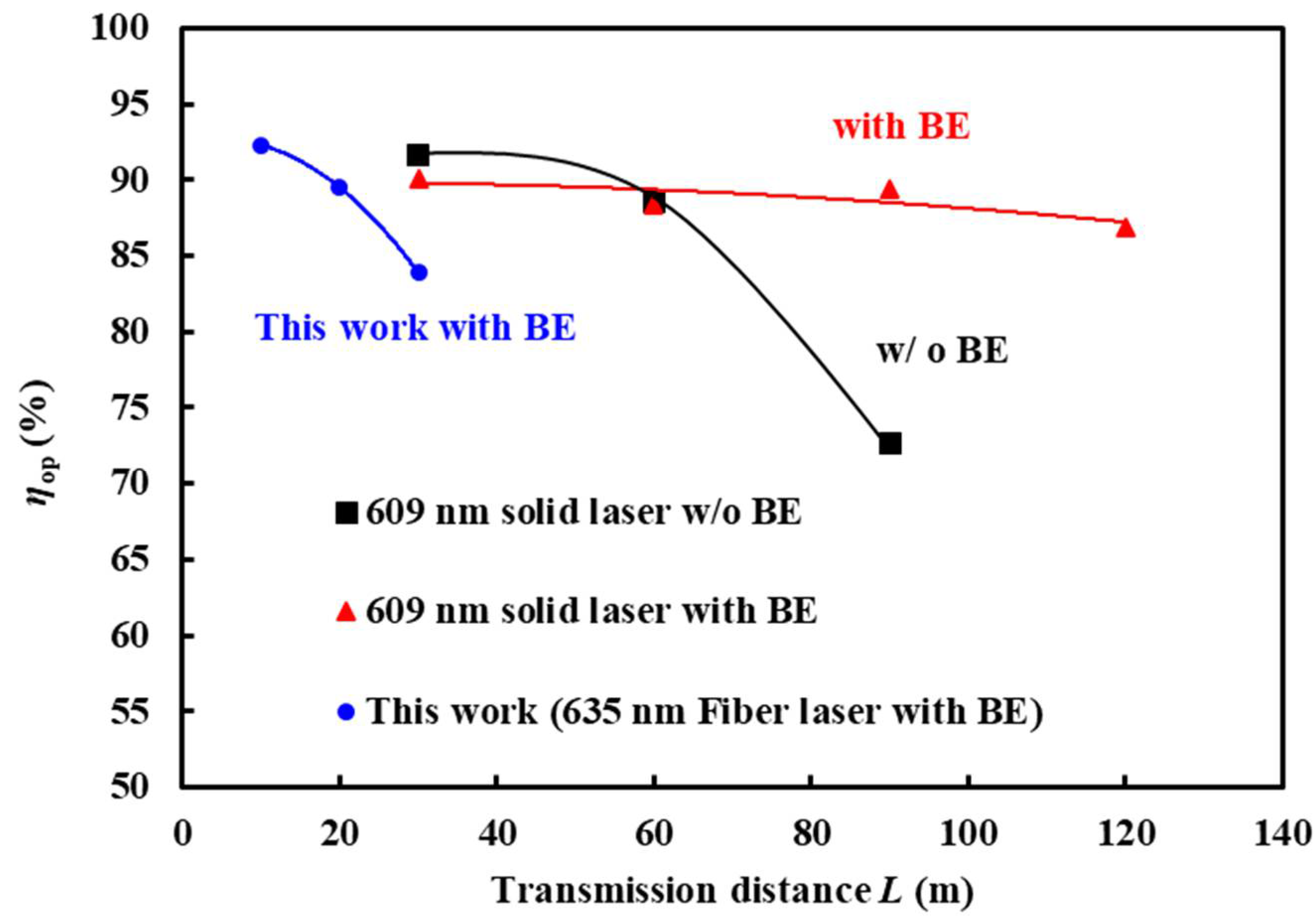
4.2. Transmission Distance

The beam divergence reduction method was earlier proposed by use of smart 3D beamforming optics by Riza lab, which could give longer collimation range to improve optical power transfer delivery efficiency for long transmission distance of 100 m and more [18]. Riza lab also experimentally demonstrated that the improved optical power transfer with beam divergence reduction was effective for a designed optical wireless link distance of 4 m [19]. In our previous report [14] on the OWPT system with the distance of 120 m using GaInP solar cells and a 609 nm laser, we achieved a photoelectric conversion efficiency of 44.3% under P2 = 46.1 mW and a system efficiency of 40.5% under P1 = 60.8 mW. In the previous experiments, the light source had a beam diameter of 2.0 mm at the aperture and a divergence angle of 1.5 mrad (0.085°). Since the 10× BE reduced the divergence angle from 1.5 mrad to 0.15 mrad (0.0085°), the optical reaching rate over a transmission distance of 60 m was improved by using the BE, as shown in Figure 6. The plots under 609 nm solid laser were calculated from [14].
In this experiment, the fiber laser we used had a large beam diameter (about 5 mm) at the aperture, and a plano-convex lens was used to direct the laser light into the 3.5 mm input aperture of the beam expander. These configurations resulted in a large divergence angle of about 2.3 mrad (0.132°) and limited the transmission distance to 10 m, indicating the plots in Figure 6. In the near future, high-power lasers with less than a divergence angle of 2.5 mrad and a small beam diameter of 2.0 mm could achieve a long transmission distance of over 100 m.

4.3. High Energy Density Power Transmission

In this experiment, we used the laser power density of 53.5 W/cm2, which corresponds to 535 times concentrated illumination in pseudo-sunlight. Under this irradiation, we obtained the photoelectric conversion efficiency of 37.2%, the system efficiency of 34.1%, and achieved the supply power density of 19.9 W/cm2. Reducing the joule heating due to the high-power laser irradiation is a significant challenge to realize this system.

5. Conclusions

We demonstrated a long-distance 10 m and high-power over 1 W optical wireless power transmission system using GaInP solar cell and 635 nm laser. On the conditions of 1.2 W laser output and 53.5 W/cm2 irradiation power density, the photoelectric conversion efficiency of 37.2% and system efficiency of 34.1% were obtained at an ambient temperature of 14 ℃. For further long-distance transmission over 100 m, an optical system is needed to suppress the divergence angle of the laser to less than 2.5 mrad. The results under high power optical density of 53.5 W/cm2 irradiation showed the potential of the W-class high-power transmission for large equipment applications and suggested the importance of reducing the heat generation of the solar cells.

Author Contributions

Conceptualization, all; methodology, all; validation, S.U.; formal analysis, Y.L.W.; investigation, Y.L.W., S.S., M.K. and S.H.; data curation, Y.L.W.; writing—original draft preparation Y.L.W.; writing—review and editing, S.U.; visualization, Y.L.W.; project administration, S.U.; funding acquisition, S.U. All authors have read and agreed to the published version of the manuscript.

Funding

This research received no external funding.

Institutional Review Board Statement

Not applicable.

Informed Consent Statement

Not applicable.

Data Availability Statement

The data that support the findings of this study are available from the corresponding author upon reasonable request.

Conflicts of Interest

The authors declare no conflict of interest.

References

  1. Shoki, H. Issues and Initiatives for Practical Deployment of Wireless Power Transfer Technologies in Japan. Proc. IEEE 2013, 101, 1312–1320. [Google Scholar] [CrossRef]
  2. Tanaka, Y.; Hamase, H.; Kanai, K.; Hasaba, R.; Sato, H.; Koyanagi, Y.; Ikeda, T.; Tani, H.; Gokan, M.; Kajiwara, S.; et al. Simulation and Implementation of Distributed Microwave Wireless Power Transfer System. IEEE Trans. Microw. Theory Tech. 2022. [Google Scholar] [CrossRef]
  3. Goto, D.; Yoshida, H.; Suzuki, H.; Kisara, K.; Ohashi, K. The Overview of JAXA Laser Energy Transmission R&D Activities and the Orbital Experiments Concept on ISS-JEM. In Proceedings of the International Conference on Space Optical Systems and Applications (ICSOS), Kobe, Japan, 7–9 May 2014; p. S5-2. [Google Scholar]
  4. Landis, G.A. Laser Power Beaming for Lunar Polar Exploration. In Proceedings of the 2020 AIAA Propulsion & Energy Forum and Exposition, Online, 24–26 August 2020. paper AIAA-2020–3538. [Google Scholar]
  5. Zhou, Y.; Miyamoto, T. 200mW-class LED-based optical wireless power transmission for compact IoT. Jpn. J. Appl. Phys. 2019, 58, SJJC04. [Google Scholar] [CrossRef]
  6. Sumi, F.H.; Dutta, L.; Saker, F. Future with Wireless Power Transfer Technology. J. Electr. Electron. Syst. 2018, 7, 1000279. [Google Scholar] [CrossRef]
  7. Hayakawa, A.; Ike, Y.; Nagaoka, R.; Nagai, T.; Wani, F. Wavefront Fluctuation Influences in Optical Energy Transmission. Rev. Laser Eng. 2019, 47, 681–683. [Google Scholar] [CrossRef]
  8. Fafard, S.; Masson, D.; Werthen, J.-G.; Liu, J.; Wu, T.-C.; Hundsberger, C.; Schwarzfischer, M.; Steinle, G.; Gaertner, C.; Piemonte, C.; et al. Power and Spectral Range Characteristics for Optical Power Converters. Energies 2021, 14, 4395. [Google Scholar] [CrossRef]
  9. Raible, D.E. High Intensity Laser Power Beaming for Wireless Power Transmission. 2008, ETD Archive. 576. Available online: https://engagedscholarship.csuohio.edu/etdarchive/576 (accessed on 13 April 2022).
  10. Helmers, H.; Lopez, E.; Höhn, O.; Lackner, D.; Schön, J.; Schauerte, M.; Schachtner, M.; Dimroth, F.; Bett, A.W. 68.9% efficient GaAs-based photonic power conversion enabled by photon recycling and optical resonance. Phys. Status Solidi (RRL) Rapid Res. Lett. 2021, 15, 2100113. [Google Scholar] [CrossRef]
  11. Fakidi, J.; Videv, S.; Kucera, S.; Claussen, H.; Haas, H. Indoor Optical Wireless Power Transfer to Small Cells at Nighttime. J. Light. Technol. 2016, 34, 3236–3258. [Google Scholar] [CrossRef] [Green Version]
  12. Steinsiek, F.; Weber, K.H.; Foth, W.P.; Foth, H.J.; Schafer, C. Wireless power transmission experiment using an airship as relay system and a moveable rover as ground target for later planetary exploration missions. In Proceedings of the 8th ESA Workshop on Advanced Space Technologies for Robotics and Automation, Noordwijk, The Netherlands, 2–4 November 2004; pp. 1–10. [Google Scholar]
  13. Komuro, Y.; Honda, S.; Kurooka, K.; Warigaya, R.; Tanaka, F.; Uchida, S. A 43.0% efficient GaInP photonic power converter with a distributed Bragg reflector under high-power 638nm laser irradiation of 17Wcm−2. Appl. Phys. Express 2021, 14, 052002. [Google Scholar] [CrossRef]
  14. Yiu Leung, W.; Shibuya, T.; Hayashi, S.; Komazawa, Y.; Kurooka, K.; Kikuchi, T.; Koga, M.; Shibui, S.; Honda, T.; Uchida, S. Long-Distance Optical Wireless Power Transmission over 100 m using GaInP Solar Cell under 609 nm Laser Irradiation. In Proceedings of the 31st International Photovoltaic Science and Engineering Conference, PVSEC-31, Online, 13–15 December 2021; Paper 63. [Google Scholar]
  15. Tai, Y.; Miyamoto, T. Experimental Configuration and Characterization of Fly-eye Lens Based Underwater Optical Wireless Power Transmission. In Proceedings of the 4th Optical Wireless and Fiber Power Transmission Conference, 4th OWPT, Online, 18–20 April 2022; OWPT3-02. [Google Scholar]
  16. Hayashi, S.; Aoki, Y.; Komuro, Y.; Sudo, T.; Kato, T.; Yiu Leung, W.; Uchida, S. Laser wireless power transmission in seawater environment. In Proceedings of the 3rd Optical Wireless and Fiber Power Transmission Conference, 3rd OWPT, Online, 19–22 April 2021; OWPT-P-09. [Google Scholar]
  17. Riza, N.A.; Huang, Y. High speed optical scanner for multi-dimensional beam pointing and acquisition. In Proceedings of the 1999 IEEE LEOS Annual Meeting Conference Proceedings. LEOS'99. 12th Annual Meeting. IEEE Lasers and Electro-Optics Society 1999 Annual Meeting (Cat. No. 99CH37009), San Francisco, CA, USA, 8–11 November 1999; Volume 1, pp. 184–185. [Google Scholar]
  18. Riza, N.A.; Khan, S.A. Ultra-low loss laser communications technique using smart beamforming optics. Opt. Commun. 2006, 257, 225–246. [Google Scholar] [CrossRef]
  19. Marraccini, P.J.; Riza, N.A. Power smart in-door optical wireless link design. J. Eur. Opt. Soc. Rapid Publ. (EOS-JEOS) 2011, 6, 11054. [Google Scholar] [CrossRef] [Green Version]
  20. Marraccini, P.J.; Riza, N.A. Smart multiple-mode indoor optical wireless design and multimode light source smart energy-efficient links. SPIE Opt. Eng. 2013, 52, 055001. [Google Scholar] [CrossRef]
  21. Zhao, M.; Miyamoto, T. Optimization for Compact and High Output LED-Based Optical Wireless Power Transmission System. Photonics 2022, 9, 14. [Google Scholar] [CrossRef]
  22. Kurooka, K.; Honda, S.; Komuro, Y.; Warigaya, R.; Uchida, S. Effect of uniform laser irradiation on the efficiency of GaAs solar cells for optical wireless power transmission. Technical Digest. In Proceedings of the 3rd Optical Wireless and Fiber Power Transmission Conference, 3rd OWPT, Online, 19–22 April 2021; OWPT-P-06. [Google Scholar]
  23. Ikeda, M.; Kaneko, K. Selenium and zinc doping in Ga0.5In0.5P and (Al0.5Ga0.5)0.5In0.5P grown by metalorganic chemical vapor deposition. J. Appl. Phys. 1989, 66, 5285. [Google Scholar] [CrossRef]
  24. Wiley, J.D. Semiconductors and Semimetals; Willardson, R.K., Beer, A.C., Eds.; Elsevier: Amsterdam, The Netherlands, 1975; Volume 10. [Google Scholar]
Figure 1. Experimental configuration used for optical wireless power transmission.
Energies 15 03690 g001
Figure 2. Experiment setup (a), Light source side view (b), and Solar cell side view (c).
Energies 15 03690 g002
Figure 3. Distributions of the laser intensity with 67.2 mW at the position (d = 140 mm) just before the focal position in (a,b) and at the position (d = 160 mm) behind the focal position in (c,d).
Energies 15 03690 g003
Figure 4. Plots of the optical reaching rate (a), photoelectric conversion efficiency (b), and system efficiency (c).
Energies 15 03690 g004
Figure 5. Isc (a), Voc (b), and FF (c) versus. incident laser power P2.
Energies 15 03690 g005
Figure 6. Relationship between optical reaching rate and transmission distance L with and without beam expander. The plots under 609 nm solid laser were calculated from [14].
Energies 15 03690 g006
Table 1. Overview of various optical wireless power transmissions.
Ref.Wavelength
(nm)
Cell TYPEIncident Energy PinDistance
(m)
ηpv
(%)
ηsystem
(%)
[8]1550InGaAs>0.5 W-36-
[9]940Si0.0560 W/cm21514.6<8.5
[10]858GaAs11.4 W/cm2-68.9-
[11]660Si0.56 W5.213.33.2
[12]532GaInP0.27 W/cm2 (4.3 W)804035
[13]638GaInP17 W/cm2 (0.3 W)-43-
Publisher’s Note: MDPI stays neutral with regard to jurisdictional claims in published maps and institutional affiliations.

