Article

Behavior of Residual Current Devices at Frequencies up to 50 kHz

Faculty of Electrical and Control Engineering, Gdańsk University of Technology, Narutowicza 11/12, PL-80-233 Gdańsk, Poland
*
Author to whom correspondence should be addressed.
Energies 2021, 14(6), 1785; https://doi.org/10.3390/en14061785
Submission received: 25 February 2021 / Revised: 16 March 2021 / Accepted: 19 March 2021 / Published: 23 March 2021
(This article belongs to the Special Issue Analysis and Experiment for Electric Power Quality)

Abstract

:
The use of residual current devices (RCDs) is obligatory in many types of low-voltage circuits. They are devices that ensure protection against electric shock in the case of indirect contact and may ensure additional protection in the case of direct contact. For the latter purpose of protection, only RCDs of a rated residual operating current not exceeding 30 mA are suitable. Unfortunately, modem current-using equipment supplied via electronic converters with a pulse width modulation produces earth fault currents composed of high-frequency components. Frequency of these components may have even several dozen kHz. Such components negatively influence the RCDs’ tripping level and, hence, protection against electric shock may be ineffective. This paper presents the results of the RCDs’ tripping test for frequencies up to 50 kHz. The results of the test have shown that many RCDs offered on the market are not able to trip for such frequencies. Such behavior was also noted for F-type and B-type RCDs which are recommended for the circuits of high-frequency components. Results of the test have been related to the requirements of the standards concerning RCDs operation. The conclusion is that these requirements are not sufficient nowadays and should be modified. Proposals for their modification are presented.

1. Introduction

Effective protection against electric shock in modern low-voltage electrical installations depends a lot on the proper selection, application, and operation of residual current devices (RCDs). Analysis of provisions of the standard HD 60364-4-41 [1] shows that the highly-sensitivity RCDs (rated residual operating current not exceeding 30 mA) are obligatory in socket-outlets circuits up to 32 A intended for general use, mobile equipment circuits up to 32 A for using in outdoors, and lighting circuits in premises designed to accommodate a single household. Even wide application of RCDs is required in special installations and locations mentioned in the 700 series of the standard HD (IEC) 60364 “Low-voltage electrical installations”. Such widespread use of RCDs as well as utilization of electronic equipment producing various shapes of earth fault currents prompt scientists and engineers from many countries to focus on the operation of RCDs under waveforms different than sinusoidal of the 50/60 Hz.
While the negative influence of the DC component of the residual current on the operation of RCDs has been recognized a long time ago [2,3] and the solutions are widely known [4,5,6,7], the influence of high frequencies is still being investigated. Papers [8,9,10,11,12,13,14] are focused on the tripping of RCDs for higher frequencies. The conclusion is that high frequency residual current changes the tripping threshold of RCDs and in some cases this threshold can be many times higher than for frequency 50 Hz. Analyses and tests presented in these papers were conducted within the relatively low frequency range—up to 1 kHz. A remedy for negative impact of the frequency up to 1 kHz is presented in [15]. The modification of the RCD’s structure, giving stable tripping current within the range 50 Hz–1 kHz, is described. The effect of frequencies lower than 50 Hz is conducted in the paper [16]. Such frequencies change the tripping threshold of RCDs—for very low frequency (e.g., 1 Hz) some RCDs may not trip at all. The impact of mixed-frequency residual currents on RCDs tripping is examined in papers [17,18,19]. They conclude that high-order harmonics may increase the tripping threshold of RCDs which can be quite dangerous for human life. Detection and analysis of the advanced signals, including distorted residual current generated in variable-speed drive circuits, are considered in [20,21]. It is mentioned that a pulse width modulated residual waveform may not be detected by some types of RCDs. A mathematical approach to the detection of distorted currents, including mixed-frequency waveforms, is presented in [22]. However, it is only a simulative study, without laboratory tests. Analysis of the provisions of the international standards referred to RCDs [23,24,25] as well as the guide [26] show that these standards provide RCDs for higher frequencies but only up to 1 kHz. Admittedly, the national German standard [27] provides RCDs, which are able to react within the extended frequency range—up to 20 kHz but this type of RCDs is not met widely. Therefore, taking into account the requirements of the international standards as well as former research, this paper presents results of the RCDs’ tripping test at frequencies up to 50 kHz. The response of the selected RCDs for such a wide frequency range is commented. Contrary to the previous tripping tests (usually up to 1 kHz) based on slowly raised residual current, the authors performed a test with suddenly applied residual current of the predetermined value. Such a test reflects a more real-life situation where exposure of the person is usually due to sudden touching of live part or exposed-conductive part. Based on the results of the test and insufficient requirements of the relevant international standards, modification of these requirements is proposed.

2. RCDs Construction and Normative Requirements Related to Their Tripping

The role of RCDs is the detection of the residual current which occurs in the case of the earth fault or direct contact of a person with live parts. Commonly used RCDs are voltage-independent and their structure is presented in Figure 1a. Elements responsible for the detection of the residual (earth) current iΔ and the tripping are a current transformer (CT) and an electromechanical relay (RY).
RCDs may also contain an electronic matching system (EC) which is used to increase the sensitivity of the RCD to the DC waveform or to ensure delay in tripping. If an RCD is dedicated specially to detect a smooth DC residual current, its construction is more complicated (Figure 1b). Moreover, such an RCD requires an auxiliary voltage (see Figure 1b: the EC-B unit is supplied from all live conductors).
The equivalent circuit of the example voltage-independent RCD is presented in Figure 2. In the case of the occurrence of the residual current iΔ, which is also the primary current of the CT, the secondary current is flows through the relay RY. If the secondary current is reaches a high enough value, the tripping of the RCD occurs (a detailed description of the RY operation can be found in [11,17]).
From the point of view of the ability of the waveform shape detection, residual current devices are divided into the following types: AC-type, A-type, F-type and B-type (B+ type). Standards [23,24,25] indicate normalized tests in order to verify whether a particular type of RCD has relevant sensitivity to a specified type of residual current.
AC-type RCDs ensure tripping for residual sinusoidal alternating currents (suddenly applied or slowly rising). Sinusoidal testing current should have network frequency, usually 50 or 60 Hz.
A-type RCDs ensure tripping for:
  • waveform the same as the AC-type;
  • residual pulsating direct currents (suddenly applied or slowly rising) having the following current delay angles: 0°, 90° and 135°;
  • residual pulsating direct current (current delay angle: 0°) superimposed by smooth direct component of 6 mA;
F-type RCDs ensure tripping for:
  • waveforms the same as the A-type;
  • residual pulsating direct currents superimposed by smooth direct component of 10 mA;
  • mixed-frequency residual current (suddenly applied or slowly rising) intended for circuit supplied between phase and neutral or phase and earthed middle conductor;
B-type RCDs ensure tripping for:
  • waveforms the same as the F-type;
  • residual sinusoidal alternating currents up to 1 kHz;
  • residual alternating currents superimposed by a smooth direct current of 0.4 times the rated residual current;
  • residual pulsating direct currents superimposed by a smooth direct current of 0.4 times the rated residual current or 10 mA, whichever has a higher value;
  • residual direct currents obtained from rectifying circuits as: two-pulse bridge connection line-to-line for 2-, 3-, and 4-pole RCDs, three-pulse star connection or six-pulse bridge connection for 3- and 4-pole RCDs;
  • residual smooth direct currents.
Residual testing currents specified for B-type RCDs may be suddenly applied or slowly increased, independent of polarity.
RCDs of type B+ have extended ability with reference to B-type RCDs—they are suitable for detection of residual sinusoidal alternating currents up to 20 kHz.
It is worth mentioning the definition of the mixed-frequency residual current specified in the standard [25], provided for testing of F-type and B-type RCDs. Table 1 presents the components (also their normative contents) of the mixed-frequency testing waveform. These components reflect:
  • Ifund—network rated frequency (usually 50 or 60 Hz);
  • I1kHz—a power electronics converter switching frequency;
  • I10Hz—a power electronics converter output frequency.
The mixed-frequency waveform having parameters from Table 1 is presented in Figure 3. One can see that the shape of the waveform practically does not depend on the phase angle of the fundamental component (50 Hz).
The intention of the standard related to F-type RCDs is to take into account high-frequency components which may occur in circuits containing power electronic converters to control the power level of current-using equipment or speed of motors in variable-speed drive circuits. In the case of the normative waveform of F-type RCDs, switching frequency on the level only equal to 1 kHz is considered. A similar conclusion is referred to B-type RCDs—only frequencies up to 1 kHz are considered. An analysis of the real circuits equipped with power electronic converters indicates that the level of frequency included in the earth fault current may be significantly higher than 1 kHz. Figure 4 depicts structure of the example circuit (variable-speed drive circuit) producing residual currents having high-frequency components, whereas Figure 5 presents oscillograms of the earth fault current recorded in such a 3-phase circuit. A pulse width modulation (PWM) frequency is equal to 3 kHz. The content of the 3 kHz component depends on the fundamental (main) output frequency which supplies a motor to obtain the desired motor speed. If the fundamental frequency is equal to 50 Hz (upper oscillogram in Figure 5), the 50 Hz component is the highest. However, if the motor is supplied by the fundamental output frequency of 10 Hz (lower oscillogram in Figure 5), the component of 3 kHz is the dominating one. Moreover, the earth current waveform contains multiples of the PWM frequency—even around 20 kHz. The problem is even worse when the PWM frequency is very high and the motor speed is very low. In the case presented in Figure 6, the PWM frequency is equal to 6.67 kHz and the fundamental frequency is 1 Hz. The 6.67 kHz component has become the main component and the multiples of the PWM frequency reach almost 50 kHz.
Taking into account the current requirements of standards related to waveforms to be detected by RCDs (mainly that RCDs are tested for frequencies only up to 1 kHz), it seems to be reasonable to perform verification of RCD’s ability for detection of residual currents having frequency even several dozen kHz (see real waveforms in Figure 5). Therefore, the latter part of this paper presents results of the tripping test of RCDs for frequencies up to 50 kHz as well as important practical conclusions resulting from this test.

3. Laboratory Test of RCDs

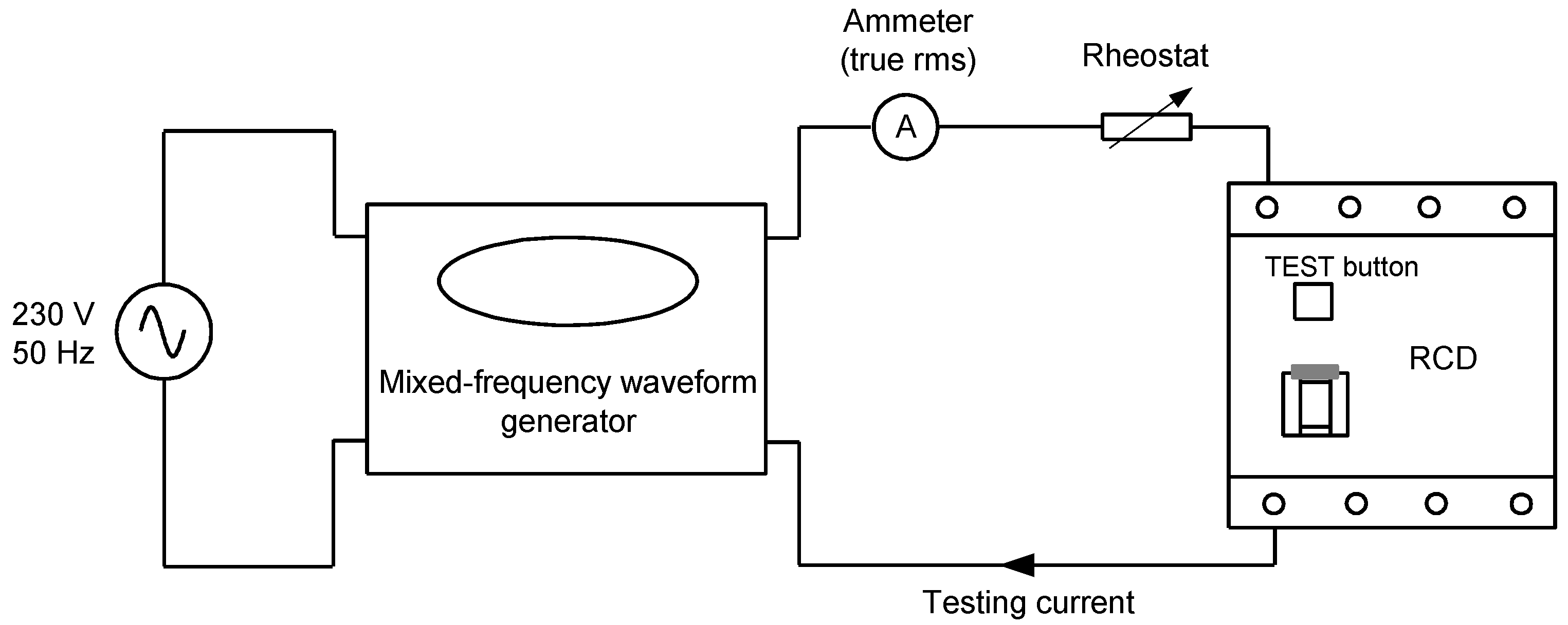
3.1. Laboratory Stand

The behavior of RCDs (AC-type, A-type, B-type, and F-type) has been verified in the laboratory using a laboratory stand. Its generalized diagram is presented in Figure 7. The laboratory stand is comprised of:
  • a power supply of 230 V, 50 Hz responsible for powering up the generator (mixed-frequency waveform generator); the generator can create a mixed-frequency signal (residual current content) up to 50 kHz;
  • an ammeter for the measurement of the current’s true rms value across the circuit during the testing stage;
  • a rheostat to achieve the exact value of residual current necessary to perform the test under the specified condition (suddenly applied residual current);
  • an RCD, to be tested.
Figure 8 visualizes the waveforms composed of a mix of two different frequency contents (as an example: 50 Hz + 1000 Hz) generated by the mixed-frequency waveform generator. All of the waveform samples were accessed with the help of dedicated software. During the RCDs test under mixed-frequency waveforms, such contents of fundamental component (50 Hz) and high-frequency component (500 Hz or 1000 Hz or 2000 Hz) were applied. When the content of both components (50 Hz and 1000 Hz) is equal to 50% (Figure 8c) the waveform shape is similar to those presented in Figure 3 (normative mixed-frequency waveform for F-type RCDs testing). The laboratory generator was also used to produce a pure sine waveform of frequency from 50 Hz to 50 kHz (for details see Section 3.2). The laboratory test aims to verify the RCDs behavior within the range much wider than the normative.

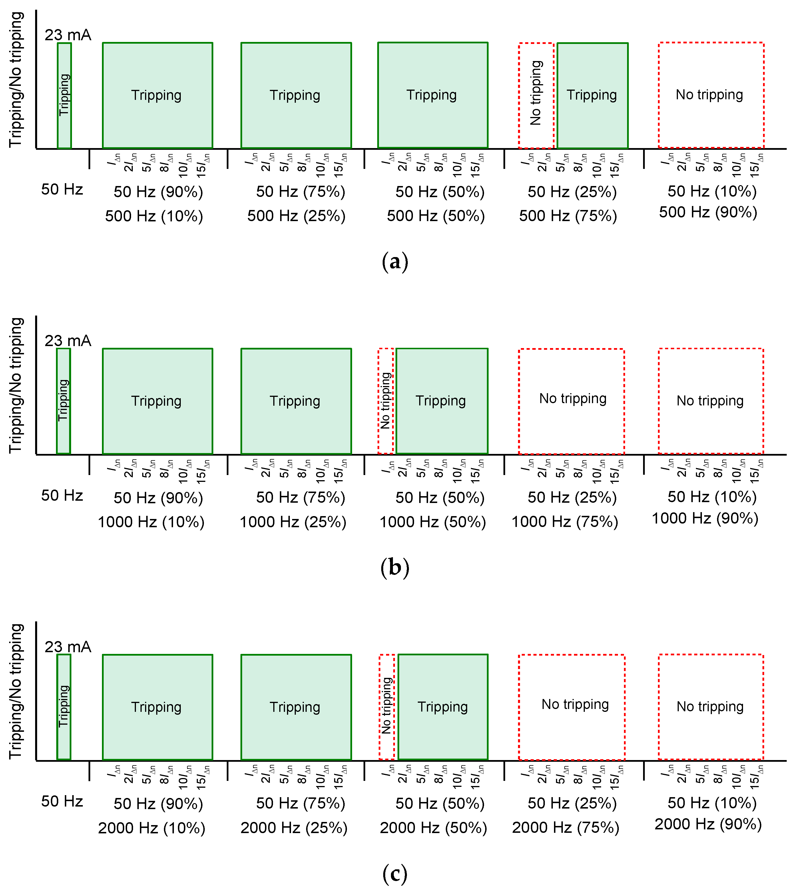
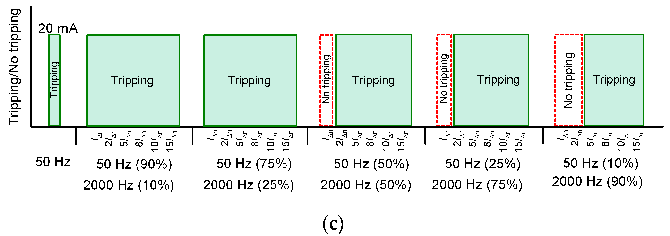
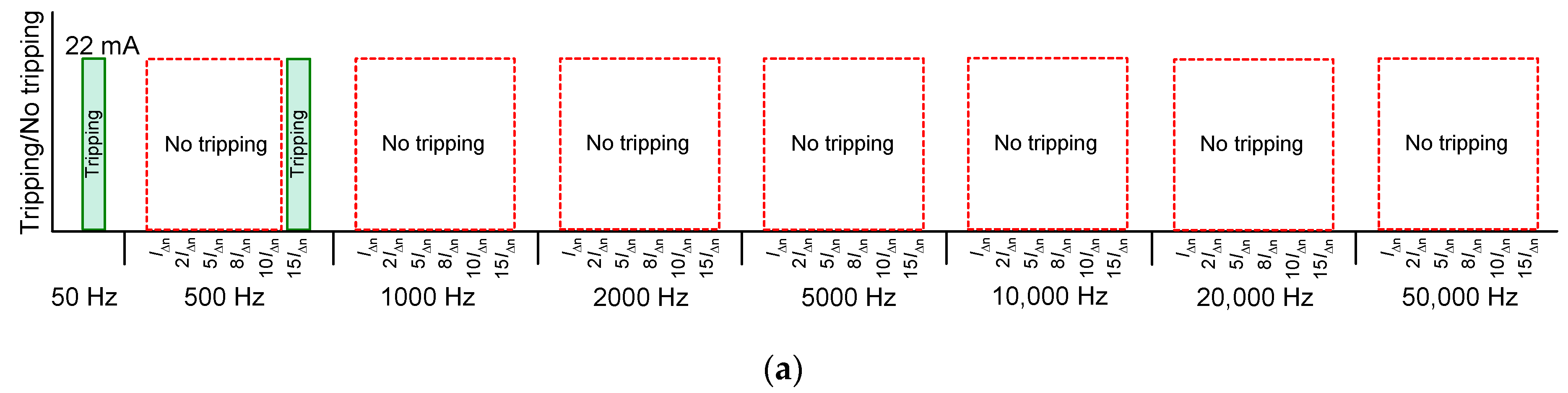
3.2. Results of the Laboratory Test

RCDs having rated residual operating current IΔn = 30 mA were tested under the suddenly applied residual current of predetermined values: IΔn; 2IΔn; 5IΔn; 8IΔn; 10IΔn and 15IΔn (i.e., 30 mA; 60 mA; 150 mA; 240 mA; 300 mA and 450 mA). Admittedly, this type of test is less restrictive than slowly raised current but it reflects the real-life situation, where a person touches a live part or exposed-conductive part after an insulation fault. The same phenomenon occurs in the case of the earth fault—the earth fault current rises suddenly. For presenting the results of the test, 10 RCDs of IΔn = 30 mA were selected as specified in Table 2. These RCDs were selected as a representative group from 14 tested RCDs (from 7 manufacturers).
The first part (initial part) of the laboratory test relied on the verification of the RCDs’ tripping under the residual current composed of the fundamental frequency (50 Hz) and one high-frequency component, consecutively 500 Hz, 1000 Hz, and 2000 Hz. This type of waveform reflects, with some approximation, dominating components included in the waveform specified in Table 1 (testing of F-type RCDs). However, for a broader look at the problem of sensitivity of RCDs, the content of both the low-frequency component (50 Hz) and the high-frequency component was changed. It is also important to underline that for a set content of the aforementioned components, e.g., 50 Hz (10%) and 1000 Hz (90%) the laboratory generator keeps the ratio of these components constant (here 10%/90%), regardless of the value of the testing current IΔn, 2IΔn, 5IΔn, 8IΔn 10IΔn, or 15IΔn. For each tested RCD, the threshold of RCDs’ sensitivity for the 50 Hz (reference value, in milliamps) was verified. According to [23,24,25], for the 50 Hz sinusoidal waveform, the normative range of the tripping threshold is (0.5–1.0)IΔn whereas for the mixed-frequency testing waveform (Table 2) is (0.5–1.4)IΔn. Results of the initial test are presented in Figure 9, Figure 10, Figure 11 and Figure 12.
When comparing results for the AC-type RCD (Figure 9) and the A-type RCD (Figure 10) one can say that their behavior (AC-type vs. A-type) is similar. Tripping of these RCDs is possible for relatively low content of the high-frequency component (10% and 25%). In such cases, the analyzed two RCDs (AC-type and A-type) tripped even for the testing current equal to IΔn (30 mA), regardless of the aforementioned share of the high-frequency component. The content of the high-frequency component equal to 50% made the problem for the AC-type RCD (Figure 9c) when the frequency was 2000 Hz. There was no tripping for the testing current equal to IΔn.
For the A-type RCD, the same problem occurred in the case of frequencies 1000 Hz and 2000 Hz (Figure 10b,c). The worst condition for RCDs tripping occurred for the highest content of the high-frequency component (90%). In the case of a high-frequency component of 500 Hz, the AC-type RCD (Figure 9a) tripped only for the testing current 15IΔn (450 mA). However, for high-frequency component equal to 1000 Hz and 2000 Hz, none of the two aforementioned RCDs reacted, even for the testing current 15IΔn.
Afterwards, while concluding the results of F-type RCD (Figure 11) and B-type RCD (Figure 12), a moderate similarity is observed in their performance, i.e., F-type vs. B-type. While considering the facts, it can be seen that both types of RCDs (F-type and B-type) behaved satisfactorily during the exposure of low content of the high-frequency component (500 Hz, 1000 Hz, 2000 Hz) i.e., 10% and 25% share. In this condition, both RCD types reacted very well to a current of IΔn (30 mA), irrespective of the share of the high-frequency component. However, subject to the 50% share of the high-frequency component, F-type RCD did not trip in the case of 2000 Hz (Figure 11c) for the residual current value of IΔn (30mA). Similarly, B-type RCD depicted the same reaction not only for 2000 Hz (Figure 12c) but also for the 500 Hz (Figure 12a) and 1000 Hz (Figure 12b). For the next contents (75% and 90%), these RCDs (F-type and B-type) behaved slightly better than the previously discussed RCDs (A-type and AC-type) but still not as suspected. During 75% high-frequency component share, F-type RCD did not trip on the current value of IΔn (30 mA) in the case of 1000 Hz (Figure 11b) and 2000 Hz (Figure 11c). On the other hand, both RCDs (F-type and B-type) remained untripped on the current value of IΔn (30 mA) and 2IΔn (60 mA) for the rest of the circumstances having a 75% share of the high-frequency component (Figure 11a and Figure 12a–c).
The scenario is similar in the case of 90% high-frequency component share, i.e., no tripping for the current of IΔn (30 mA) and 2IΔn (60 mA) (Figure 11a–c and Figure 12a,b) except for 2000 Hz where B-type RCD (Figure 12c) tripped only in the case of 8IΔn (240 mA), 10IΔn (300 mA), and 15IΔn (450 mA).
The second part (main part) of the laboratory test was devoted to the verification of the RCDs tripping under the sinusoidal residual current of the following higher frequencies (consecutively): 500 Hz; 1000 Hz; 2000 Hz; 5000 Hz; 10,000 Hz; 20,000 Hz; and 50,000 Hz. Similar to the previous test, the residual current was suddenly applied and had predetermined values: IΔn; 2IΔn; 5IΔn; 8IΔn; 10IΔn; and 15IΔn. Results of the test are presented in Figure 13, Figure 14, Figure 15 and Figure 16.
Analysis of the results from Figure 13 enables one to conclude that AC-type RCDs may have various sensitivity to high-frequency residual currents. Very unfavorable behavior was observed for RCD_1AC (Figure 13a). Its tripping was noted only for frequency 500 Hz and value of the residual current equal to 15IΔn = 450 mA. Clearly better behavior was noted for RCD_3AC (Figure 13c). Tripping of this RCD occurred even for 5 kHz but the value of the residual current had to be higher than 2IΔn = 60 mA. Unfortunately, frequencies of the residual current 10 kHz, 20 kHz, and 50 kHz were too high to make tripping of the tested AC-type RCDs, even for the value of the current 15 times higher than the rated residual operating current of the RCD.
While going through the results achieved from the testing of A-type RCDs (Figure 14), their outcomes are not very promising. It is evident that all three A-type RCDs reacted well on the nominal frequency, i.e., 50 Hz. Afterwards, RCD_1A (Figure 14a) did not show any reaction on the rest of the frequencies (500 Hz, 1 kHz, 2 kHz, 5 kHz, 10 kHz, 20 kHz, and 50 kHz). A similar reaction was witnessed in the case of RCD_2A (Figure 14b), where the A-type RCD could not trip at all except for the frequency of 500 Hz but only for the highest residual current value, i.e., 15IΔn (450 mA). Likewise, an identical outcome was experienced for the RCD_3A (Figure 14c), where RCD_3A tripped for the frequency values of 500 Hz, 1 kHz, and 2 kHz but only at the highest residual current value which is 15IΔn (450 mA). Apart from that, unfortunately, RCD_3A failed to trip on the rest of the higher frequencies.
Figure 15 states the results achieved from the testing of F-type RCDs. The results again are not very favorable. Although the F-type RCDs are supposed to perform well on the higher frequencies, contrary to this, RCD_1F (Figure 15a) only tripped typically on the nominal frequency (50 Hz). During testing of higher frequencies, for 500 Hz, this RCD failed to trip at the residual current values of IΔn, 2IΔn, 5IΔn, and for 1 kHz it only reacted for the residual current value equal to 15IΔn. Beyond this point, RCD_1F remained untripped even for the highest residual current of 15IΔn. For the RCD_2F (Figure 15b), the reaction was identical for nominal frequency but for 500 Hz the RCD_2F did not react for the residual current values of IΔn, 2IΔn, whereas, in the case of 1 kHz, RCD_2F tripped only beyond the residual current value of 5IΔn. For the higher frequencies (5 kHz, 10 kHz, 20 kHz, and 50 kHz), RCD_2F showed negative results and did not trip at any of the residual current value (Figure 15b).
Figure 16 depicts the results for the most advanced RCDs—B-type RCDs. They are considered typically for higher frequency purpose but only up to 1 kHz, according to [25]. Starting from the nominal frequency (50 Hz), both RCD_1B (Figure 16a) and RCD_2B (Figure 16b) performed well. At the threshold of 500 Hz both RCDs did not react at the residual current value of IΔn and 2IΔn. For 1 kHz, both RCDs (RCD_1B and RCD_2B) tripped only above the residual current value of 5IΔn. Moving to the higher frequency of 2 kHz, unfortunately, both B-type RCDs only showed tripping just for the highest value of the residual current (15IΔn). Past this point, for frequencies 5 kHz, 10 kHz, 20 kHz, and 50 kHz, RCD_1B as well as RCD_2B did not react to the testing residual currents.

4. Discussion: Summary of the Test; Proposed Changes in Standards

Residual current devices’ usage has been made obligatory not only from the modern domestic point of view but as well as for industrial purposes. The principal objective of this device is protection against electric shock in the case of either direct or indirect contact. The most challenging situation for such devices is when they are exposed to residual currents containing high-frequency contents. Under such circumstances this device may not be able to trip at the expected threshold and, therefore protection against electric shock may not be ensured. RCDs in this research were subjected to two different test categories. The first stage of the test included a mixed-frequency signal (nominal frequency + high-frequency component) and the reaction of the RCDs was quite unsatisfactory. In this initial testing stage, all types of RCDs (AC-type, A-type, F-type, and B-type) demonstrated tripping for the lowest testing current (IΔn) only when the high-frequency content share was low, which means 10% or 25%. Once the high-frequency content was raised to 50% and beyond (75% or 90%), the RCD’s tripping threshold moved to higher values or no tripping occurred (Figure 9, Figure 10, Figure 11 and Figure 12). Furthermore, in the second testing stage, RCDs were exposed to high-frequency sinusoidal residual current. Again, the behavior of RCDs was unexpected as one of the AC-type RCD (Figure 13c) performed well enough, although the AC-type RCD is not dedicated for higher frequencies. As far as the other types are concerned, B-type and F-type RCDs functioned unsatisfactorily for higher frequencies and did not even respond to the very high residual current value (15IΔn).
Regarding the risk of harmful effects of the electric shock, it should be commented that, according to IEC 60479-2 [28], the threshold of perception, the threshold of let-go and the threshold of ventricular fibrillation move to higher values when a high-frequency current flows. The most important is the last threshold (fibrillation effect) and it is the most-dependent on frequency. Analyzing provisions of the [25,28], it can be indicated that for the frequency equal to 400 Hz, the threshold of ventricular fibrillation is around 6 times higher than at the 50 Hz (i.e., one may assume 30 mA for 50 Hz but 6 × 30 mA = 180 mA for 400 Hz). For the frequency equal to 1000 Hz, this threshold changes 14 times (analogically: 14 × 30 mA = 420 mA). What is more, the standard [28] informs that for a mixed-frequency signal, the ventricular fibrillation hazard may be estimated (a rough approximation) as equivalent to the hazard caused by a pure sinusoidal current Iev-sin having the fundamental frequency with an amplitude equivalent to the quadratic summation of all component amplitudes Ih individually affected by the appropriate frequency factor Ffactor (e.g., Ffactor = 6 for 400 Hz and Ffactor = 14 for 1000 Hz):
I ev - sin = h = 1 n ( I h F factor , h ) 2
Therefore, in terms of the ventricular fibrillation, high-frequency currents are less dangerous for persons than a current having frequency equal to 50 Hz. This phenomenon (tripping characteristic vs. the threshold of ventricular fibrillation) is utilized by some manufacturers of 30 mA B-type RCDs. The standard [25], in provisions dedicated only to B-type RCDs, specifies residual operating current IΔnf for two higher frequencies: 400 Hz (IΔnf = 6IΔn) and 1000 Hz (IΔnf = 14IΔn), where IΔn is a rated residual operating current for the nominal frequency (50 Hz). It is confirmation of the aforementioned comment related to the effect of high-frequency current on persons—the values of the residual operating current correspond to the threshold of ventricular fibrillation. In practice, such an increase of the tripping threshold is acceptable only for RCDs having IΔn ≤ 30 mA for 50 Hz. Unfortunately, the standard [25] indicates the increase of the residual operating current only up to 1 kHz, what is insufficient nowadays. Moreover, standards do not differentiate thermal effect (the dissipated power in the human body) of the 50 Hz current vs. high-frequency currents—it is assumed to be approximately constant.
Results obtained within the frame of this research indicate a need to extend provisions of standards related to RCDs performance and tests. Normative test of B-type RCDs up to only 1 kHz is insufficient nowadays. Similarly, a mixed-frequency testing waveform having the high-frequency component 1 kHz (normative testing of F-type and B-type RCDs) is also insufficient. Contemporary installations comprising power electronics converters may produce harmonics of a level equal to several dozen kHz (see Figure 5 and Figure 6). It is proposed to move the value of the aforementioned normative high-frequency component from 1 kHz to at least 10 kHz. It is also recommended to introduce a new type of RCDs, which could ensure stable tripping up to 50 kHz (alternatively 150 kHz; upper limit of supraharmonics—taking into account fast development and wide use of power electronics converters). These proposed modifications must be respected by RCDs’ manufacturers.
With reference to the improvement of the construction of RCDs (from the point of view of the high frequency), special attention should be given to the current transformer CT of the RCD, its relay RY, and the optional electronic matching system EC (Figure 2). Parameters of the aforementioned elements should be selected, coordinated, and verified for the expected operating frequency range.

5. Conclusions

Research conducted by the authors and its results presented in this paper show that there is a strong effect of frequency on the tripping threshold of RCDs. While up to 1 kHz the tripping of RCDs was noted, for frequencies 5 kHz, 10 kHz, 20 kHz, and 50 kHz there were no RCDs reactions to the test currents (except one AC-type RCD reacting to the 5 kHz), even 15 times higher than the rated residual current of the RCD. What is worse, unfavorable behavior was noted also for F-type and B-type RCDs, which are dedicated to circuits having earth fault current with harmonics. No tripping of F-type and B-type RCDs for frequencies at levels of a few or several dozen kHz is due to the current state of the normative requirements. International standards require tests for frequencies not higher than 1 kHz—RCDs have to react only to this level of frequency. In the light of the switching frequency used in modern power electronics converters, such a level of testing frequency (1 kHz) seems to be insufficient. Therefore, it is proposed to raise the threshold of the normative testing current from 1 kHz to at least 10 kHz. For special applications, a separate type of RCDs is recommended to be provided. RCDs of the special type (frequency-proof) should be able to trip for frequencies up to 50 kHz.

Author Contributions

Conceptualization, S.C.; methodology, S.C.; validation, S.C.; formal analysis, S.C.; investigation, S.C. and H.T.; resources, S.C.; writing—original draft preparation, S.C. and H.T.; writing—review and editing, S.C. and H.T.; visualization, S.C. and H.T.; supervision, S.C. All authors have read and agreed to the published version of the manuscript.

Funding

This research was supported by Gdańsk University of Technology.

Institutional Review Board Statement

Not applicable.

Informed Consent Statement

Not applicable.

Data Availability Statement

Data is contained within the article.

Conflicts of Interest

The authors declare no conflict of interest.

References

  1. CENELEC. HD 60364-4-41:2017. Low-Voltage Electrical Installations—Part 4-41: Protection for Safety—Protection Against Electric Shock; European Committee for Electrotechnical Standardization: Brussels, Belgium, 2017. [Google Scholar]
  2. Rösch, H. Current-operated ELCBs for AC. and pulsating DC fault currents. Siemens Power Eng. 1981, 8–9, 252–255. [Google Scholar]
  3. Rösch, H. Fehlerstrom-Schutzschalter zum Schutz gegen gefährliche Körperströme. ETZ 1989, 12, 580–584. [Google Scholar]
  4. Solleder, R. Allstromsensitive Fehlerstrom-Schutzeinrichtung fur Industrieanwendung. ETZ 1994, 115, 896–901. [Google Scholar]
  5. Han, Y.; Ding, C.; Shou, X. Design & implementation of an A-type residual current circuit breaker IC. In Proceedings of the 2012 IEEE International Symposium on Industrial Electronics, Hangzhou, China, 28–31 May 2012. [Google Scholar] [CrossRef]
  6. Guolei, X.; Yan, S.; Juwei, Y.; Chengcong, L.; Binfeng, W.; Feng, J.; Weidong, J. Research on the principle of residual current protection technology based on transient waveform criterion. E3S Web Conf. 2020, 204, 02009. [Google Scholar] [CrossRef]
  7. Yao, W.; Kui, L.; Can, L.; Zhitao, G.; Feng, N.; Xiujuan, Z. Study on modeling and simulation of AC/DC sensitive residual current transformer. In Proceedings of the 1st International Conference on Electric Power Equipment—Switching Technology, Xi’an, China, 23–27 October 2011. [Google Scholar] [CrossRef]
  8. Czaja, P. Examination of the impact of design of a residual current protective device on the release frequency range. In Proceedings of the 2017 Progress in Applied Electrical Engineering (PAEE), Koscielisko, Poland, 25–30 June 2017. [Google Scholar] [CrossRef]
  9. Czapp, S.; Horiszny, J. Simulation of residual current devices operation under high frequency residual current. Prz. Elektrotechniczny 2012, 2, 242–247. [Google Scholar]
  10. Erdei, Z.; Horgos, M.; Lung, C.; Pop-Vadean, A.; Muresan, R. Frequency behavior of the residual current devices. IOP Conf. Ser. Mater. Sci. Eng. 2017, 163, 012053. [Google Scholar] [CrossRef] [Green Version]
  11. Freschi, F. High-frequency behavior of residual current devices. IEEE Trans. Power Deliv. 2012, 27, 1629–1635. [Google Scholar] [CrossRef] [Green Version]
  12. Horgos, M.; Erdei, Z.; Barz, C.; Birsan, I.; Ilia, M. Contributions to testing residual current devices at different frequency values. In Proceedings of the 6th International Conference on Modern Power Systems (MPS), Cluj-Napoca, Romania, 18–21 May 2015. [Google Scholar]
  13. Shopov, Y.; Filipova-Petrakieva, S.; Boychev, B. Investigation of residual current devices in high frequencies. In Proceedings of the 10th Electrical Engineering Faculty Conference (BulEF), Sozopol, Bulgaria, 11–14 September 2018. [Google Scholar]
  14. Xie, P.; Fang, Z.; Hu, J.; Yang, J.; Zhu, G. Tripping characteristics of residual current devices under different working conditions. In Proceedings of the 3rd IEEE Conference on Energy Internet and Energy System Integration, Changsha, China, 8–10 November 2019. [Google Scholar]
  15. Czapp, S.; Dobrzynski, K.; Klucznik, J.; Lubosny, Z.; Kowalak, R. Improving sensitivity of residual current transformers to high frequency earth fault currents. Arch. Elect. Eng. 2017, 66, 485–494. [Google Scholar] [CrossRef]
  16. Czapp, S.; Dobrzynski, K.; Klucznik, J.; Lubosny, Z. Low-frequency tripping characteristics of residual current devices. In Proceedings of the 2017 IEEE International Conference on Environmental and Electrical Engineering & 2017 IEEE Industrial and Commercial Power Systems Europe (EEEIC /I&CPS Europe), Milan, Italy, 6–9 June 2017; pp. 298–301. [Google Scholar] [CrossRef]
  17. Czapp, S. The effect of earth fault current harmonics on tripping of residual current devices. In Proceedings of the International School on Nonsinusoidal Currents and Compensation, IX Conference-Seminar (ISNCC), Lagow, Poland, 10–13 June 2008. [Google Scholar] [CrossRef]
  18. Lee, T.M.; Chan, T.W. The effects of harmonics on the operational characteristics of residual current circuit breakers. In Proceedings of the International Conference on Energy Management and Power Delivery, Singapore, 21–23 November 1995; pp. 715–719. [Google Scholar] [CrossRef]
  19. Wieland, T.; Aigner, M.; Schmautzer, E.; Pasker, J.; Fickert, L. Influences on safety issues for inverter supplied grid structures. In Proceedings of the 2012 Electric Power Quality and Supply Reliability, Tartu, Estonia, 11–13 June 2012. [Google Scholar] [CrossRef]
  20. Rabcan, J.; Levashenko, V.; Zaitseva, E.; Kvassay, M.; Subbotin, S. Application of fuzzy decision tree for signal classification. IEEE Trans. Ind. Inf. 2019, 15, 5425–5434. [Google Scholar] [CrossRef]
  21. Gruhn, T.; Glenney, J.; Savostianik, M. Type B ground-fault protection on adjustable frequency drives. IEEE Trans. Ind. Appl. 2018, 54, 934–939. [Google Scholar] [CrossRef]
  22. Panda, R.K.; Veeramalla, J. Behavior modeling of a type B RCD. In Proceedings of the 1st IEEE International Conference on Power Electronics, Intelligent Control and Energy Systems (ICPEICES), Delhi, India, 4–6 July 2016. [Google Scholar]
  23. IEC. IEC 60755:2017. General Safety Requirements for Residual Current Operated Protective Devices; International Electrotechnical Commission: Geneva, Switzerland, 2017. [Google Scholar]
  24. IEC. IEC 61008-1:2010. Residual Current Operated Circuit-Breakers without Integral Overcurrent Protection for Household and Similar Uses (RCCB)—Part 1: General Rules; International Electrotechnical Commission: Geneva, Switzerland, 2010. [Google Scholar]
  25. IEC. IEC 62423:2009. Type F and Type B Residual Current Operated Circuit-Breakers with and without Integral Overcurrent Protection for Household and Similar Uses; International Electrotechnical Commission: Geneva, Switzerland, 2009. [Google Scholar]
  26. Eaton. Residual Current Devices. In Application Guide; Eaton: Vienna, Austria, 2017. [Google Scholar]
  27. VDE. DIN VDE 0664-400:2020-03. Residual Current Operated Circuit-Breakers Type B without Integral Overcurrent Protection to Operate at Residual Alternating and Residual Direct Currents for Advanced Preventative Protection against Fire–Part 400: RCCB Type B+; VDE: Berlin, Germany, 2020. [Google Scholar]
  28. IEC. IEC 60479-2:2007(2019). Effects of Current on Human Beings and Livestock–Part 2: Special Aspects; International Electrotechnical Commission: Geneva, Switzerland, 2019. [Google Scholar]
Figure 1. Structure of residual current devices (RCDs): (a) voltage-independent (AC-type, A-type, F-type); (b) voltage-dependent (B-type); RCD—residual current device; CT, CT1, CT2—current transformers; EC—electronic matching system (e.g., to increase the sensitivity to the DC pulsating waveform); EC-B—electronic system which ensures tripping especially in the case of the smooth DC residual current; RY—relay.
Energies 14 01785 g001
Figure 2. Equivalent circuit of the RCD: es—induced secondary voltage; iΔ—residual (primary) current; is—secondary current; C—matching capacitor; RFe—resistance representing excitation losses; Lμ—inductance with magnetic hysteresis; Rp, Lp,—parameters (resistance and inductance) of the CT primary winding; Rs, Ls—parameters (resistance and inductance) of the CT secondary winding; RRY, LRY—parameters (resistance and inductance) of the relay.
Energies 14 01785 g002
Figure 3. Mixed-frequency waveform composed of components presented in Table 1; phase angle of the I1kHz and I10Hz is 0°; phase angle of the Ifund (50 Hz) is: (a) 0°; (b) 180°.
Energies 14 01785 g003
Figure 4. A variable-speed drive circuit producing residual currents of high-frequency components; RCD—residual current device; iΔ—residual current; PWM—pulse width modulation.
Energies 14 01785 g004
Figure 5. Oscillograms of the earth fault current in a variable-speed drive circuit (earth fault at the motor terminals). Upper oscillogram: the motor is supplied by frequency 50 Hz (rated motor speed); lower oscillogram: the motor is supplied by frequency 10 Hz (slow motor speed); pulse width modulation (PWM) frequency: 3 kHz.
Energies 14 01785 g005
Figure 6. Oscillogram of the earth fault current in a variable-speed drive circuit (earth fault at the motor terminals). The motor is supplied by frequency 1 Hz (very slow motor speed); pulse width modulation (PWM) frequency: 6.67 kHz.
Energies 14 01785 g006
Figure 7. Laboratory stand for RCDs testing.
Energies 14 01785 g007
Figure 8. Example waveforms (time: 10 ms/div) composed of two frequencies, generated by the laboratory generator: (a) 50 Hz (90%) and 1000 Hz (10%); (b) 50 Hz (75%) and 1000 Hz (25%); (c) 50 Hz (50%) and 1000 Hz (50%); (d) 50 Hz (25%) and 1000 Hz (75%); (e) 50 Hz (10%) and 1000 Hz (90%).
Energies 14 01785 g008
Figure 9. Tripping of the 30 mA AC-type RCD (no. RCD_1AC—symbol defined in Table 2) for waveform composed of the fundamental frequency (50 Hz) and high-frequency component: (a) 500 Hz; (b) 1000 Hz; (c) 2000 Hz. Values in brackets indicate the content of the particular component; 22 mA—real tripping current for a pure sinusoidal signal of 50 Hz.
Energies 14 01785 g009
Figure 10. Tripping of the 30 mA A-type RCD (no. RCD_1A—symbol defined in Table 2) for waveform composed of the fundamental frequency (50 Hz) and high-frequency component: (a) 500 Hz; (b) 1000 Hz; (c) 2000 Hz. Values in brackets indicate the content of the particular component; 23 mA—real tripping current for a pure sinusoidal signal of 50 Hz.
Energies 14 01785 g010
Figure 11. Tripping of the 30 mA F-type RCD (no. RCD_1F—symbol defined in Table 2) for waveform composed of the fundamental frequency (50 Hz) and high-frequency component: (a) 500 Hz; (b) 1000 Hz; (c) 2000 Hz. Values in brackets indicate the content of the particular component; 20 mA—real tripping current for a pure sinusoidal signal of 50 Hz.
Energies 14 01785 g011aEnergies 14 01785 g011b
Figure 12. Tripping of the 30 mA B-type RCD (no. RCD_2B—symbol defined in Table 2) for waveform composed of the fundamental frequency (50 Hz) and high-frequency component: (a) 500 Hz; (b) 1000 Hz; (c) 2000 Hz. Values in brackets indicate the content of the particular component; 21 mA—real tripping current for a pure sinusoidal signal of 50 Hz.
Energies 14 01785 g012
Figure 13. Tripping of the 30 mA AC-type RCDs for a sine waveform of the specified frequency from 50 Hz to 50 kHz: (a) RCD_1AC; (b) RCD_2AC; (c) RCD_3AC; symbols defined in Table 2.
Energies 14 01785 g013aEnergies 14 01785 g013b
Figure 14. Tripping of the 30 mA A-type RCDs for a sine waveform of the specified frequency from 50 Hz to 50 kHz: (a) RCD_1A; (b) RCD_2A; (c) RCD_3A; symbols defined in Table 2.
Energies 14 01785 g014
Figure 15. Tripping of the 30 mA F-type RCDs for a sine waveform of the specified frequency from 50 Hz to 50 kHz: (a) RCD_1F; (b) RCD_2F; symbols defined in Table 2.
Energies 14 01785 g015
Figure 16. Tripping of the 30 mA B-type RCDs for a sine waveform of the specified frequency from 50 Hz to 50 kHz: (a) RCD_1B; (b) RCD_2B; symbols defined in Table 2.
Energies 14 01785 g016
Table 1. Components of the mixed-frequency testing waveform used for F-type and B-type RCDs.
Components of the Waveform
IfundI1kHzI10Hz
0.138·IΔn0.138·IΔn0.035·IΔn
Table 2. List of the selected RCDs (IΔn = 30 mA).
Consecutive RCDSymbol/No. of the RCDTypeManufacturer (Symbol)
1RCD_1ACACMan_1
2RCD_2ACACMan_2
3RCD_3ACACMan_3
4RCD_1AAMan_1
5RCD_2AAMan_3
6RCD_3AAMan_4
7RCD_1FFMan_5
8RCD_2FFMan_6
9RCD_1BBMan_7
10RCD_2BBMan_6
Publisher’s Note: MDPI stays neutral with regard to jurisdictional claims in published maps and institutional affiliations.

