Article

A Parametrical Study on Convective Heat Transfer between High-Temperature Gas and Regenerative Cooling Panel

College of Aerospace Science, National University of Defense Technology, Changsha 410073, China
*
Author to whom correspondence should be addressed.
Energies 2021, 14(6), 1784; https://doi.org/10.3390/en14061784
Submission received: 9 February 2021 / Revised: 15 March 2021 / Accepted: 18 March 2021 / Published: 23 March 2021
(This article belongs to the Section J: Thermal Management)

Abstract

:
Thermal protection is still one of the key challenges for successful scramjet operations. In this study, the three-dimensional coupled heat transfer between high-temperature gas and regenerative cooling panel with kerosene of supercritical pressure flowing in the cooling channels was numerically investigated to reveal the fundamental characteristics of regenerative cooling as well as its influencing factors. The SST k-ω turbulence model with low-Reynolds-number correction provided by the pressure-based solver of Fluent 19.2 is adopted for simulation. It was found that the heat flux of the gas heated surface is in the order of 106 W/m2, and it declines along the flow direction of gas due to the development of boundary layer. Compared with cocurrent flow, the temperature peak of the gas heated surface in counter flow is much higher. The temperature and heat flux of the gas heated surface both rises with the static pressure and total temperature of gas. The heat flux of the gas heated surface increases with the mass flow rate of kerosene, and it hardly changes with the pressure of kerosene. Results herein could help to understand the real heat transfer process of regenerative cooling and guide the design of thermal protection systems.

1. Introduction

Thermal protection is one of the key challenges in the application of scramjet engines [1]. Among the available cooling methods, the active regenerative cooling using endothermic hydrocarbon fuel as coolant is recommended as the most effective way for its high efficiency and low performance loss [2,3,4,5,6].
Since temperature and heat flux are the crucial design parameters for thermal protection, many researchers conducted research to investigate the wall temperature and heat flux of scramjet engines. Kennedy et al. [7,8] experimentally measured the heat flux of the scramjet combustor walls by heat flux sensors, and it was found that the heat flux of the combustor wall varied from 200 kW/m2 to 1500 kW/m2. In order to measure the extremely high temperature and heat flux of the scramjet combustor, Li et al. [9] developed an integrated water-cooled sensor and conducted numerical and experimental investigations to test the response characteristics and stability of the sensor, calibration results indicated that the sensor could meet the measurement requirements. By installing heat-flux sensors on the combustor wall, systematic experimental research was carried out to obtain the wall heat flux distribution at different locations of the supersonic combustor, it was found that the equivalence ratio has little impact on the distribution of heat flux [10].
Compared with experimental measurements, numerical simulations could significantly reduce cost and save time. Numerical studies indicated that for a regenerative cooling combustor, the boundary conditions and heat transfer of the combustor wall could be solved by the gradient-based method [11]. The numerical investigation of Wang et al. [12] indicated that the wall heat flux is greatly influenced by the flow and combustion characteristics, which leads to the high non-uniform distribution of heat flux in the supersonic combustor. Besides, researchers found that the heat conduction of the combustor wall can be estimated by the conjugate gradient method, in which the transient temperature and heat flux of the inner wall is obtained through the measurement of outer wall temperature, and the difference between simulation results and experimental measurements was found to be less than 5% [13].
In the present research of aero engines, endothermic hydrocarbon fuel is recommended as the fuel because of its high volumetric energy density [14]. Since the operating pressure in the cooling channels is usually higher than the critical pressure, lots of work has been done to study the flow and heat transfer characteristics of hydrocarbon fuels at supercritical pressures [15,16]. According to Wang et al. [17], the heat transfer deterioration can be caused by the pseudo-film boiling in the near wall region. For kerosene flowing in a heated horizontal tube at supercritical pressures, the variation of density would induce buoyancy, which would lead to secondary flow and influence the heat transfer, and the buoyancy effect decreases with the rise of pressure because of smaller variation of density [18]. In order to further understand the buoyancy effect, Sun et al. [19] conducted large eddy simulations and investigated the detailed flow and heat transfer of n-decane in a heated upward circular tube at supercritical pressures, and it was found that the influence of buoyancy is strongly related to the flowing state of fuel.
Thermal cracking would occur when the temperature of endothermic hydrocarbon fuel is pretty high, which would influence the flow and heat transfer [20]. According to Lei et al. [21], the cooling capacity can be promoted by thermal cracking, which is beneficial for the thermal protection. Therefore, the flow and heat transfer of endothermic hydrocarbon fuels with thermal pyrolysis was extensively studied. Based on their experimental studies, Li et al. [22] proposed a simplified molecular reaction kinetic model of high accuracy that can be used to simulate the pyrolysis of supercritical endothermic hydrocarbon fuels in heated tubes. Li et al. [23] also found that pyrolysis would enhance the heat transfer when heat flux is relatively low while the influence of pyrolysis on heat transfer at higher heat flux is much more complicated. The work of Xu et al. [24] indicated that the ribbed surface would greatly improve the heat transfer in the channel, leading to lower wall temperature and weakens the pyrolysis of the endothermic fuel.
Although there are many literatures concerning the thermal protection and regenerative cooling of scramjet engines, most of them has been simplified to a certain extent. For example, the electric heating experiments were used to model the thermal environment of the cooling channels [25,26], or the flow and heat transfer characteristics of hydrocarbon fuel were numerically investigated at a given wall heat flux [27,28]. The coupled heat transfer of high-temperature gas and regenerative cooling panel are seldom taken into consideration in the existing literatures. It can be deduced that for convective heat transfer between high-temperature gas and combustor wall, higher wall temperature would lead to lower heat flux. However, for heat transfer of coolant in the cooling panel, higher wall temperature would lead to higher heat flux. The temperature and heat flux of the combustor wall may not match through separated research. Since the heat transfer of regenerative cooling is a strongly coupled process, it is better to solve the problem as a whole. Therefore, the three-dimensional coupled heat transfer between high-temperature gas, regenerative cooling panel with parallel cooling channels and kerosene of supercritical pressure are numerically investigated in this paper. The fundamental characteristics of coupled heat transfer as well as its influencing factors are studied and discussed combined with theoretical analysis. The simulation results herein could help to reveal the real heat transfer process of regenerative cooling and can be used for the design and optimization of thermal protection systems.
The block diagram of this paper is shown in Figure 1.

2. Numerical Methods

2.1. Governing Equations

The finite volume method provided by the pressure-based solver of ANSYS Fluent 19.2 is used for numerical simulations in this study. The Reynolds averaging method is adopted to simulate the flow and heat transfer. For steady flow and heat transfer of fluid with no external force and heat source, the governing equations in Reynold’s averaging are as follows.
Continuity equation:
x i ρ u i = 0
Momentum equation:
x j ρ u i u j = P x i + x j μ u i x j + u j x i 2 3 μ δ i j u k x k + x j ρ u i u j ¯
The Reynolds stress based on the Boussinesq hypothesis has the following form:
ρ u i u j ¯ = μ t u i x j + u j x i 2 3 δ i j ρ k + u k x k
Energy equation:
u i ρ E x i + u i P x i = x j λ T x j + c p μ t Pr t T x j + u i x j μ u i x j + u j x i 2 3 μ δ i j u k x k
Tao et al. [29] numerically investigated the heat transfer of hydrocarbon fuel at supercritical pressures, and it was found that the SST k-ω model [30] is more accurate than other models in most cases. The work of Wang et al. [12] indicated that the SST k-ω model could accurately simulate the flow and reaction in the scramjet combustor and predict the heat flux of the combustor walls. Therefore, the SST k-ω turbulence model with low-Reynolds-number correction is adopted for simulation in this paper.
Equation of turbulent kinetic energy k:
t ( ρ k ) + x i ( ρ k u i ) = x j ( Γ k k x j ) + G ˜ k Y k + S k
Equation of specific dissipation rate ω:
t ( ρ ω ) + x i ( ρ ω u i ) = x j ( Γ ω ω x j ) + G ω Y ω + D ω + S ω
Detailed descriptions of the constants and the coefficients can be found in the work of Menter [30].
The three-dimensional heat conduction equation in the solid zone:
x i ( λ T x i ) + x j ( λ T x j ) + x k ( λ T x k ) + q ˙ = ρ c T τ
For constant thermal conductivity without heat source, the steady-state heat conduction equation in the solid zone can be written as:
2 T x i 2 + 2 T x j 2 + 2 T x k 2 = 0
By combining the continuity equation, momentum equation and energy equation of the fluid while solving the heat conduction equation in the solid region, and adopting coupled heat transfer for the convective heat transfer between solid walls and fluid zone, the three-dimensional coupled heat transfer between high-temperature gas and regenerative cooling panel can be solved.

2.2. Physical Model

The detailed schematic diagram of a scramjet engine can be found in the work of Goyne et al [31]. The simplified schematic diagram of scramjet engine and regenerative cooling is shown in Figure 2. It can be seen that for regenerative cooling in scramjet engines, heat is transmitted from high-temperature gas to the cooling panel through convection, and is transferred inside the cooling panel through conduction, and finally it is absorbed by kerosene of supercritical pressure through convection. The heat transfer through radiation is not considered in this study because of its small proportion in total heat flux [32].
The experimental photos of scramjet engine and regenerative cooling are shown in Figure 3. The temperature and heat flux of the gas heated surface are measured by embedded thermocouples and heat flux sensors in the experiments. However, the installation of thermocouples and heat flux sensors would change the origin configuration of the cooling panel. Besides, the local flow and heat transfer characteristics are also affected by the installation of thermocouples and heat flux sensors, which may lead to significant errors. Therefore, the proposed research could help to reveal the heat transfer characteristics of regenerative cooling and its influencing factors.
The convective heat flux qg of the gas heated surface is calculated as:
q g = h g ( T a w T w g )
where hg is the convective heat transfer coefficient of high-temperature gas, Taw is the actual adiabatic wall temperature while Twg is the wall temperature of the gas heated surface.
The equivalent conductive heat flux qp in the cooling panel can be calculated as:
q p = λ δ p ( T w g T w c ) = h p , e q ( T w g T w c )
where λ is the thermal conductivity of the panel material, δp is the thickness of the gas side wall, hp,eq can be considered as the equivalent heat transfer coefficient of the cooling panel and Twc is the wall temperature at the coolant side.
The equivalent convective heat flux qc in the cooling channels can be calculated as:
q c = h c , e q ( T w c T b )
where hc,eq is the equivalent convective heat transfer coefficient of kerosene and Tb is the bulk temperature of kerosene. According to the energy conservation, we can get the following equation:
q = h g ( T a w T w g ) = h p , e q ( T w g T w c ) = h c , e q ( T w c T b )
Therefore, the heat flux and wall temperature are strongly coupled. Formula (12) can be written in the form of equivalent thermal resistance according to the heat transfer direction as follows:
q = T a w T w g 1 / h g = T w g T w c 1 / h p , e q = T w c T b 1 / h c , e q = T a w T b 1 / h g + 1 / h p , e q + 1 / h c , e q = T a w T b R e q
where Req is the equivalent total thermal resistance.
The computational domain is shown in Figure 4. The size of the cooling channel is 3 mm × 3 mm, and the thicknesses of the ribs and walls are all 3 mm. An entry section of 180 mm in length is included to ensure a fully developed channel flow, and an exit section of 180 mm is used to reduce the impact of the exit segment. The mass-flow-inlet boundary condition was applied for the inlet of kerosene, where mass flow rate and inlet temperature are specified. The pressure-outlet boundary condition is applied for the outlet of kerosene. According to the state equation of ideal gas, the total pressure of high-temperature gas can be determined by the mass flow rate, static pressure and total temperature. Therefore, the inlet of high-temperature gas is also set as mass flow inlet, where mass flow rate, static pressure and total temperature are specified. The outlet of high-temperature gas is set as pressure outlet. The gas heated surface and cooling channel walls are set as coupled walls, while other walls or surfaces are set as symmetry or adiabatic walls in order to match the actual physical process. The flowing direction of high-temperature gas is along the positive direction of z-axis. The material of cooling panel is steel, and a constant thermal conductivity 20 W·K−1·m−1 of steel is used for simulation. The complicated reaction in the combustor is not solved in the research, and uniform incoming flow of high-temperature gas is used for simulation. The mass fraction of high-temperature gas is N2 in 53.1%, O2 in 23.3%, CO2 in 14.6%, and H2O in 9.0% for all cases.
The parameters of the simulation cases are listed in Table 1. Tin is the inlet temperature of kerosene, Pc is the pressure of kerosene, and mc is the mass flow rate of kerosene in a single cooling channel. mg is the mass flow rate of high-temperature gas, T0 is the total temperature of high-temperature gas, and Pg,s is the static pressure of high-temperature gas. The operating pressure is zero for all cases.
The high-temperature gas contains several components. The ideal gas model is used to define the density of all the components. Two 4th-order polynomials as function of temperature are applied to calculate the specific heat of gas in temperature ranges of 300 K-1000 K and of 1000 K-5000 K respectively. The viscosity and thermal conductivity coefficient are calculated by kinetic theory. The properties of the mixed high-temperature gas are calculated through ideal gas mixing law.
The China no. 3 aviation kerosene RP-3 is used as coolant in this study. The thermophysical properties of RP-3 at supercritical pressures can be obtained by experimental measurements [33,34,35], or regarded as multi-component substitutions [29,36] and calculated by the SUPERTRAPP program [37]. In this paper, a 10-component substitution model proposed by Zhong et al. [36] is used to calculate the physical properties of supercritical pressure kerosene. The thermophysical properties of the 10-component kerosene as function of temperature at different supercritical pressures are shown in Figure 5.

2.3. Validation

To our best knowledge, there is still no detailed experimental data of the coupled heat transfer between high-temperature gas and regenerative cooling panel in published literatures that can be used for simulation validation. In order to verify the accuracy of the proposed method, the simulation and theoretical calculations of three-dimensional coupled heat transfer between high-temperature gas and cooling panel with no ribs inside are conducted. The physical model of the three-dimensional coupled heated transfer used for numerical validation is shown in Figure 6. For theoretical analysis and calculations, the heat transfer of high-temperature gas is calculated by the method recommended by Eckert [38] for high-speed flow. The heat conduction in the solid zone is calculated by Fourier’s law. To take into account the property variations, the Sieder-Tate relation [39] is used to calculate the heat transfer of kerosene. The height of the channel is 2 mm, and an equivalent hydraulic diameter 4 mm is used for theoretical calculations. The inlet conditions of high-temperature gas and kerosene in the validation simulation are consistent with Case#1. The comparison of bulk temperature Tb of kerosene, wall temperature Twg and heat flux qg at the gas heated surface between simulation and theoretical calculations is shown in Figure 7. Results indicated that there is no obvious difference of Tb between simulation and theoretical calculations, and the distinction of Twg is less than 15 K. Besides, the relative difference of qg between simulation and theoretical calculations is within 5%. Therefore, the numerical method can be used to simulate the three-dimensional coupled heat transfer of regenerative cooling.

2.4. Mesh Sensitivity

Case#1 is chosen to test the mesh sensitivity with kerosene flowing along the positive direction of z-axis, and five different meshes are used for the test. The information of different meshes is listed in Table 2. Nc is the number of elements in the kerosene zone, Np is the number of elements in the solid zone, Ng is the number of elements in the gas zone, and Ntot is the total number of elements in the whole computational domain.
The heat flux qg at the centerline of the gas heated surface along the flow direction is shown in Figure 8. The simulation results of Mesh#1 and Mesh#2 are significantly different from those of Mesh#3, Mesh#4 and Mesh#5, while the relative distinction of qg in Mesh#3, Mesh#4 and Mesh#5 is within 0.5%. Therefore, Mesh#3 is sufficient for numerical simulations in this study. The grid division at the cross section of the computational domain in Mesh#3 is shown in Figure 9.

3. Results and Discussion

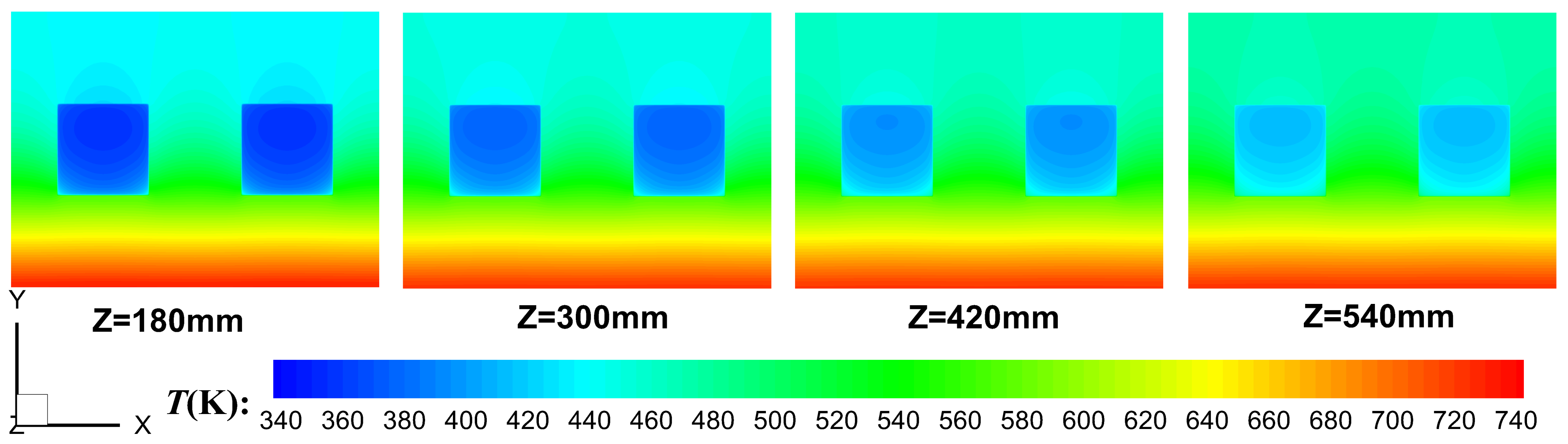
3.1. Primary Characteristics of Regenerative Cooling

The primary characteristics of Case#1 with kerosene flowing along the positive direction of z-axis are discussed in this section.
The contour graph of wall temperature Twg and heat flux qg at the gas heated surface of the cooling panel is shown in Figure 10a,b, respectively. It can be seen that Twg first declines and then rises along the flow direction. The variation of Twg is less than 10 K at the gas heated surface, and the relative difference of Twg is within 2%. The heat flux qg of the gas heated surface is in the order of 106 W/m2. It is obvious that qg decreases along the whole flow direction. The decline of qg is more than 140 kW/m2, which means that qg dropped as much as 13% along the flow direction. Besides, the difference of Twg and qg in x direction is very small, thus the temperature Twg and heat flux qg at the centerline of the gas heated surface is used for analysis instead of contour graphs in the rest of the article.
Since the flow and heat transfer is strongly coupled according to Equation (12), the analysis of Twg and qg should be combined with the flow and heat transfer characteristics of high-temperature gas and kerosene. The loss in stagnation temperature T0 of high-temperature gas is very small along the flow direction, thus the adiabatic wall temperature Taw can be considered as constant. Since the variation of wall temperature Twg is less than 10 K, the decline of qg along the flow direction is mainly caused by the decrease of hg. A reasonable assumption is that the decrease of hg along the flow direction is mainly caused by the development of boundary layer at the gas heated surface. The assumption can be confirmed by the velocity distribution of high-temperature gas in Figure 11. Since the thickness of boundary layer keeps increasing along the flow direction, the heat transfer resistance between gas and cooling panel increases, which leads to the decrease of hg and qg along the flow direction.
As kerosene flowing through the cooling channel and being heated, the bulk temperature Tb of kerosene increases along the flow direction. The density and viscosity of kerosene decreases, the velocity and Reynolds number of kerosene increases, which promotes the heat transfer coefficient hc of kerosene in the cooling channels. According to Equation (12), the reduction of hg and the increase of hc would lead to the decline of Twg, while the increase of Tb would lead to the rise of Twg. The wall temperature Twg first declines and then rises along the flow direction, which is a result due to the combination of these two factors.
The temperature of the cooling panel and kerosene at different locations of the cross section is shown in Figure 12. It is obvious that there is a significant stratification of temperature in the cooling panel near the gas heated surface. The distance between different temperature layers in this zone is almost the same, indicating that the temperature gradient and heat flux of the cooling panel can be considered as uniform near the gas heated surface. There is no obvious stratification of temperature in the cooling panel close to the adiabatic wall, which means that the heat flux in this zone is small, and the temperature stratification in this zone gradually diminishes along the flow direction. There is also a significant stratification of temperature in the cooling channels. As kerosene flowing through the cooling channels and being heated, the kerosene near the gas heated wall is of higher temperature, while kerosene of lower temperature is gathered in the zone away from the gas heated wall.

3.2. Influencing Factors of Coupled Heat Transfer

The material and configuration of the cooling panel in an engine generally remains unchanged, thus the coupled heat transfer is mainly affected by the flowing direction of coolant as well as the flowing parameters of gas and coolant. The influencing factors of coupled heat transfer are studies and discussed in the following sections.

3.2.1. Flowing Direction of Kerosene

The bulk temperature Tb and heat transfer coefficient hc of kerosene in the cooling channels would change with the flowing direction of kerosene, leading to the change of wall temperature Twg and heat flux qg of the gas heated surface.
The coupled heat transfer between high-temperature gas and cooling panel with kerosene flowing along the negative direction of z-axis was conducted, in which the flowing parameters of high-temperature gas and kerosene are consistent with Case#1. For kerosene flowing along the positive direction of z-axis, the flow is defined as cocurrent flow. For kerosene flowing along the negative direction of z-axis, the flow is defined as counter flow. The variation of Tb and hc along the z-axis in cocurrent and counter flow is shown in Figure 13. It can be seen that for cocurrent flow, Tb and hc rises along the positive direction of z-axis, while for counter flow, Tb and hc rises along the negative direction of z-axis.
The variation of wall temperature Twg and heat flux qg at the centerline of the gas heated surface in cocurrent and counter flow is shown in Figure 14. It is obvious that for counter flow, Twg and qg both declines along the flow direction of gas. The variation of Twg in counter flow is more drastic, while the variation of qg in counter flow is smaller. Besides, the peak of Twg in counter flow is much higher than that in cocurrent flow. Compared with counter flow, cocurrent flow can better meet the requirements of thermal protection. Therefore, the flowing direction of high-temperature gas and kerosene are both along the positive direction of z-axis in the subsequent study.

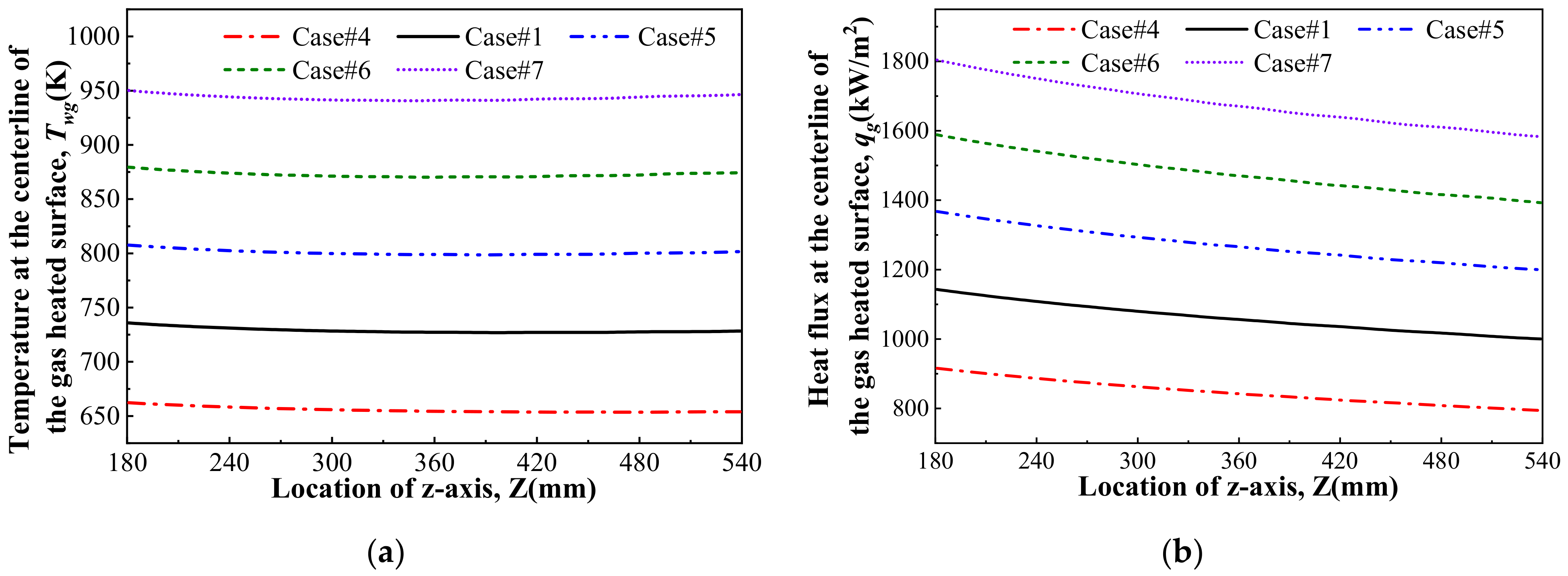
3.2.2. Flowing Parameters of High-Temperature Gas

The flowing parameters of high-temperature gas are investigated in this section.
The heat transfer between regenerative cooling panel and high-temperature gas of different static pressure is conducted in Case#2 and Case#3. Compared with Case#1, the static pressure and mass flow rate of gas is changed in Case#2 and Case#3, while the total temperature, Mach number and static temperature remains unchanged. The variation of wall temperature Twg and heat flux qg at the centerline of the gas heated surface in these cases is shown in Figure 15. The results showed that Twg and qg increase significantly with the static pressure of high-temperature gas. Since the inlet total temperature and Mach number of gas are the same in Case#1, Case#2 and Case#3, the adiabatic wall temperature Taw is almost the same in these cases. Therefore, according to Equation (9), the increase of Twg and qg is mainly caused by the increase of hg. The density and mass flow rate of gas increases with static pressure, the Reynolds number and heat transfer coefficient hg of gas also increases with static pressure. Therefore, it can be deduced from Equations (12) and (13) that Twg and qg will also increase with the static pressure of gas. When the static pressure of gas increases from 50 kPa to 75 kPa, the average increase of Twg and qg is 85.2 k and 255.5 kW/m2, respectively. When the static pressure of gas increased from 75 kPa to 100 kPa, the average increase of Twg is 71.7 k, and the average increase of qg is 210.6 kW/m2.
The heat transfer coefficient hg and Nusselt number Nug of high-temperature gas at different static pressures is shown in Figure 16. As is shown in Figure 16a, hg increases with the static pressure of high-temperature gas, and declines along the flow direction. For static pressure of 50 kPa, 75 kPa and 100 kPa, the decline of hg along the flow direction is 12.7%, 13.1% and 13.6% respectively, which means the decline of hg along the flow direction increases with the static pressure of gas. The main reason may be that the density and viscosity of gas increases with the static pressure, which promotes the development of boundary layer, leading to a larger decline of hg. Figure 16b indicates that Nug increases with the static pressure of gas. Besides, it can be seen that Nug increases along the flow direction, and the increment of Nug along the flow direction increases with the rise of static pressure.
The heat transfer between regenerative cooling panel and high-temperature gas of different total temperature is conducted in Case#4 to Case#7. Compared with Case#1, the total temperature of gas is changed in Case#4 to Case#7, while the mass flow rate and static pressure remains unchanged. The variation of wall temperature Twg and heat flux qg at the centerline of the gas heated surface in these cases is shown in Figure 17. The results showed that Twg and qg almost increases linearly with the increase of T0. The rise of Twg is about 72 K and the rise of qg is about 210 kW/m2 for every 300 K increase of T0. The main reason is that the adiabatic wall temperature Taw increases with T0, and according to Equations (12) and (13), this will lead to the rise of Twg and qg.
The heat transfer coefficient hg and Nusselt number Nug of high-temperature gas at different total temperatures along the flow direction is shown in Figure 18. The relative distinction of hg at different total temperature is less than 2%. The velocity and viscosity of the gas increases with the rise of T0, while the density of gas decreases with that, leading to a slight decrease in Reynolds number, which would lead to a small drop of hg. However, the thermal conductivity of the gas increases slightly with the rise of T0, which would lead to a small rise of hg. Therefore, the heat transfer coefficient hg of high-temperature gas is almost the same at different total temperature. Figure 18b indicates that Nug decreases with the rise of T0. Besides, it can be seen that Nug increases along the flow direction, and the increment of Nug along the flow direction decreases with the rise of T0.

3.2.3. Flowing Parameters of Kerosene

The flowing parameters of kerosene are investigated in this section.
Case#8 and Case#9 are conducted to study the influence of supercritical pressure of kerosene. Compared with Case#1, the supercritical pressure of kerosene in the cooling channels is changed in Case#8 and Case#9, while the mass flow rate and inlet temperature remain unchanged. The variation of wall temperature Twg and heat flux qg at the centerline of the gas heated surface in these cases is shown in Figure 19. The results showed that both Twg and qg are almost the same in these cases. The temperature of kerosene in the cooling channels is below 600 K in Case#1, Case#8 and Case#9. According to Figure 5, the difference of thermophysical properties of kerosene at different supercritical pressures can be neglected when temperature is below 600 K. Therefore, the flow and heat transfer of kerosene in the cooling channels are almost the same at different supercritical pressures, and the difference in Twg and qg can be neglected.
Case#10 to Case#13 are conducted to study the influence of mass flow rate of kerosene. Compared with Case#1, the mass flow rate of kerosene is changed in Case#10 to Case#13, while the inlet temperature and pressure of kerosene remains unchanged. The variation of wall temperature Twg and heat flux qg at the centerline of the gas heated surface in these cases is shown in Figure 20. The variation of bulk temperature Tb, heat transfer coefficient hc and Nusselt number Nuc in the cooling channels is shown in Figure 21. The results showed that qg rises with the increases of mass flow rate of kerosene, while Twg declines with that. The increase in mass flow rate of kerosene promotes the Reynolds number and heat transfer coefficient hc of kerosene in the cooling channels, which reduces the total heat resistance and promotes the overall heat transfer. It can be seen from Figure 21 that for constant increment of kerosene, the variation of Tb and hc declines with the mass flow rate of kerosene. Therefore, for constant increment of kerosene, the variation of Twg and qg also decreases with the mass flow rate of kerosene. Besides, the results also showed that the region where Twg rises along the flow direction decreases with the mass flow rate of kerosene. The main reason is that the bulk temperature Tb of kerosene rises more slowly along the flow direction at larger mass flow rate of kerosene. Figure 21c indicates that Nuc increases with the increase of mass flow rate of kerosene. Besides, it can be seen that Nuc increases along the flow direction, and the increment of Nuc along the flow direction decreases with the increase of mass flow rate of kerosene.

4. Conclusions

Regenerative cooling is crucial for the thermal protection of scramjet engines. Therefore, the three-dimensional coupled heat transfer between high temperature gas and regenerative cooling panel with kerosene of supercritical pressure flowing in the cooling channels was numerically investigated in this paper. Compared with other research, the heat convection of high-temperature gas in the combustor, the heat conduction in the cooling panel and heat convection of kerosene in the cooling channels were solved simultaneously in the present study. The temperature and heat flux of the gas heated surface are obtained, and the influencing factors of regenerative cooling were also investigated.
The heat flux of the gas heated surface is found to be in the order of 106 W/m2 at the present investigation conditions. The temperature of the gas heated surface in cocurrent flow first declines and then rises along the flow direction of gas, while it declines along the flow direction of gas in counter flow. The temperature variation of the gas heated surface in counter flow is more drastic, while the heat flux variation in counter flow is smaller. Compared with counter flow, cocurrent flow can better meet the requirements of thermal protection because the temperature peak of the gas heated surface in counter flow is much higher than that in cocurrent flow.
Parametric investigations indicated that the temperature and heat transfer of the gas heated surface are greatly influenced by the flowing parameters of high-temperature gas and mass flow rate of kerosene, while they are almost unaffected by the supercritical pressure of kerosene in the cooling channels. The heat transfer coefficient of high-temperature gas is almost the same at different total temperature, while Nusselt number of it decreases with total temperature. Although the heat transfer coefficient of kerosene increases along the flow direction in cocurrent flow, the heat flux of the gas heated surface decreases along the flow direction due to the development of boundary layer at the gas heated surface.
Since the three-dimensional coupled heat transfer of regenerative cooling is realized in the research, the proposed method can be used to study the influence of panel configuration and results can be used to guide the structural design and optimization. Besides, the proposed method can be improved for further investigation of the semi-active (or semi- passive) cooling as well as film cooling in the future.

Author Contributions

Methodology, J.Z.; project administration, Y.P.; numerical simulations and original draft, J.H. and N.W.; writing—review and editing, N.W. and J.H. All authors have read and agreed to the published version of the manuscript.

Funding

This research was funded by National Natural Science Foundation of China (11572346) and Natural Science Foundation of Hunan Province, China (2020JJ4666).

Data Availability Statement

Data is contained within the article.

Acknowledgments

The authors would like to express their special thanks to National Supercomputing Center in Changsha for software and resource supporting.

Conflicts of Interest

The authors declare no conflict of interest.

Nomenclature

cpIsobaric specific heat capacity (J·kg−1·K−1)
ETotal energy of fluid (J)
hHeat transfer coefficient (W·K−1·m−2)
kTurbulent kinetic energy (m2·s−2)
mMass flow rate (kg·s−1)
MaMach number
NNumber of elements
NuNusselt number
PPressure (Pa)
PrPrandtl number
qHeat flux (W·m−2)
ReReynolds number
TTemperature (K)
ui, (i, j, k)Velocities in x, y, z directions (m·s−1)
u i , (i, j, k)Deviation of ui from its average amplitude (m·s−1)
xi, (i, j, k)Cartesian coordinate
x, y, zaxis
δThickness (m)
δijKronecker delta
λThermal conductivity (W·K−1·m−1)
μDynamic viscosity (kg·m1·s1)
ρDensity (kg·m−3)
τTime (s)
ωSpecific dissipation rate (s−1)
Subscripts
aadiabatic
bbulk
ccoolant
eqequivalent
ggas
ininlet
ppanel
sstatic
tturbulent
tottotal
wwall

References

  1. Bertin, J.J.; Cummings, R.M. Fifty years of hypersonics: Where we’ve been, where we’re going. Prog. Aerosp. Sci. 2003, 39, 511–536. [Google Scholar] [CrossRef] [Green Version]
  2. Zhang, S.L.; Li, X.; Zuo, J.Y.; Qin, J.; Cheng, K.L.; Feng, Y.; Bao, W. Research progress on active thermal protection for hypersonic vehicles. Prog. Aerosp. Sci. 2020, 119, 100646. [Google Scholar] [CrossRef]
  3. Zhu, Y.H.; Wei, P.; Xu, R.N.; Jiang, P.X. Review on active thermal protection and its heat transfer for airbreathing hypersonic vehicles. Chin. J. Aeronaut. 2018, 31, 1929–1953. [Google Scholar] [CrossRef]
  4. Zhang, S.L.; Qin, J.; Zhou, W.X.; Bao, W. Review on regenerative cooling for hypersonic propulsion. J. Propuls. Technol. 2018, 39, 23–36. (In Chinese) [Google Scholar]
  5. Kilkovský, B. Review of design and modeling of regenerative heat exchangers. Energies 2020, 13, 759. [Google Scholar] [CrossRef] [Green Version]
  6. Gou, J.J.; Chang, Y.; Yan, Z.W.; Chen, B.; Gong, C.L. The design of thermal management system for hypersonic launch vehicles based on active cooling networks. Appl. Therm. Eng. 2019, 159, 113938. [Google Scholar] [CrossRef]
  7. Kennedy, P.J.; Donbar, J.M.; Trelewicz, J.R.; Gouldstone, C.; Longtin, J.P. Heat flux measurements in a scramjet combustor using direct write technology. In Proceedings of the 17th AIAA International Space Planes and Hypersonic Systems and Technologies Conference, San Francisco, CA, USA, 11–14 April 2011. [Google Scholar]
  8. Trelewicz, J.R.; Longtin, J.P.; Gouldstone, C.; Kennedy, P.J.; Donbar, J.M. Heat flux measurements in a scramjet combustor using embedded direct-write sensors. J. Propul. Power. 2015, 31, 1003–1013. [Google Scholar] [CrossRef]
  9. Li, L.; Fan, X.J.; Wang, J. Measurements of wall heat flux and temperature in a supersonic model combustor. In Proceedings of the 47th AIAA/ASME/SAE/ASEE Joint Propulsion Conference and Exhibit, San Diego, CA, USA, 31 July–3 August 2011. [Google Scholar]
  10. Cheng, D.; Wang, J.; Lu, Y.; Li, L.; Yao, W.; Fan, X.J. Wall heat flux measurements for a kerosene-fueled supersonic combustor. J. Aerosp. Eng. 2019, 32, 04019080. [Google Scholar] [CrossRef] [Green Version]
  11. Cui, M.; Mei, J.; Zhang, B.-W.; Xu, B.-B.; Zhou, L.; Zhang, Y. Inverse identification of boundary conditions in a scramjet combustor with a regenerative cooling system. Appl. Therm. Eng. 2018, 134, 555–563. [Google Scholar] [CrossRef]
  12. Wang, X.; Zhong, F.Q.; Gu, H.B.; Zhang, X.Y. Numerical study of combustion and convective heat transfer of a Mach 2.5 supersonic combustor. Appl. Therm. Eng. 2015, 89, 883–896. [Google Scholar] [CrossRef] [Green Version]
  13. Cheng, L.W.; Zhong, F.Q.; Gu, H.B.; Zhang, X.Y. Application of conjugate gradient method for estimation of the wall heat flux of a supersonic combustor. Int. J. Heat Mass Transf. 2016, 96, 249–255. [Google Scholar] [CrossRef]
  14. Sobel, D.R.; Spadaccini, L.J. Hydrocarbon fuel cooling technologies for advanced propulsion. J. Eng. Gas Turb. Power 1997, 119, 344–351. [Google Scholar] [CrossRef]
  15. Zhao, Y.; Wang, Y.; Liang, C.; Zhang, Q.Y.; Li, X.Y. Heat transfer analysis of n-decane with variable heat flux distributions in a mini-channel. Appl. Therm. Eng. 2018, 144, 695–701. [Google Scholar] [CrossRef]
  16. Lv, L.L.; Wen, J.; Fu, Y.C.; Quan, Y.K.; Zhu, J.Q.; Xu, G.Q. Numerical investigation on convective heat transfer of supercritical aviation kerosene in a horizontal tube under hyper gravity conditions. Aerosp. Sci. Technol. 2020, 105, 105962. [Google Scholar] [CrossRef]
  17. Wang, Y.H.; Lu, Y.N.; Li, S.F.; Dong, M. Numerical study on non-uniform heat transfer deterioration of supercritical RP-3 aviation kerosene in a horizontal tube. Chin. J. Chem. Eng. 2020, 28, 1542–1557. [Google Scholar] [CrossRef]
  18. Sun, X.; Meng, H.; Zheng, Y. Asymmetric heating and buoyancy effects on heat transfer of hydrocarbon fuel in a horizontal square channel at supercritical pressures. Aerosp. Sci. Technol. 2019, 93, 105358. [Google Scholar] [CrossRef]
  19. Sun, X.; Meng, H. Large eddy simulations and analyses of hydrocarbon fuel heat transfer in vertical upward flows at supercritical pressures. Int. J. Heat Mass Transf. 2021, 170, 120988. [Google Scholar] [CrossRef]
  20. Lei, Z.L.; He, K.; Huang, Q.; Bao, Z.W.; Li, X.Y. Numerical study on supercritical heat transfer of n-decane during pyrolysis in rectangular tubes. Appl. Therm. Eng. 2020, 170, 115002. [Google Scholar] [CrossRef]
  21. Lei, Z.L.; Liu, B.; Huang, Q.; He, K.; Bao, Z.W.; Zhu, Q.; Li, X.Y. Thermal cracking characteristics of n-decane in the rectangular and circular tubes. Chinese J. Chem. Eng. 2019, 27, 2876–2883. [Google Scholar] [CrossRef]
  22. Li, Z.Z.; Wang, H.Y.; Jing, K.; Wang, L.M.; Li, Y.; Zhang, X.W.; Liu, G.Z. Kinetics and modeling of supercritical pyrolysis of endothermic hydrocarbon fuels in regenerative cooling channels. Chem. Eng. Sci. 2019, 207, 202–214. [Google Scholar] [CrossRef]
  23. Li, Z.Z.; Liu, G.Z.; Zhang, R.L. Heat transfer to supercritical hydrocarbon fuel in horizontal tube: Effects of near-wall pyrolysis at high heat flux. Chem. Eng. Sci. 2021, 229, 115994. [Google Scholar] [CrossRef]
  24. Xu, K.K.; Sun, X.; Meng, H. Conjugate heat transfer, endothermic fuel pyrolysis and surface coking of aviation kerosene in ribbed tube at supercritical pressure. Int. J. Therm. Sci. 2018, 132, 209–218. [Google Scholar] [CrossRef]
  25. Zhao, W.Z.; Song, Z.C.; Li, H.Z.; Gu, H.F.; Tuo, X.B.; Zheng, Y.L.; Wang, H.J. Research on heat transfer characteristics of kerosene at supercritical pressure in circular tubes. Exp. Therm. Fluid Sci. 2018, 96, 507–515. [Google Scholar] [CrossRef]
  26. Wang, Y.H.; Li, S.F.; Dong, M. Experimental investigation on heat transfer deterioration and thermoacoustic instability of supercritical-pressure aviation kerosene within a vertical upward circular tube. Appl. Therm. Eng. 2019, 157, 113707. [Google Scholar] [CrossRef]
  27. Sun, X.; Xu, K.K.; Meng, H.; Zheng, Y. Buoyancy effects on supercritical-pressure conjugate heat transfer of aviation kerosene in horizontal tubes. J. Supercrit. Fluids 2018, 139, 105–113. [Google Scholar] [CrossRef]
  28. Jiao, S.; Li, S.F.; Pu, H.; Dong, M.; Shang, Y. Investigation of pyrolysis effect on convective heat transfer characteristics of supercritical aviation kerosene. Acta Astronaut. 2020, 171, 55–68. [Google Scholar] [CrossRef]
  29. Tao, Z.; Cheng, Z.Y.; Zhu, J.Q.; Li, H.W. Effect of turbulence models on predicting convective heat transfer to hydrocarbon fuel at supercritical pressure. Chin. J. Aeronaut. 2016, 29, 1247–1261. [Google Scholar] [CrossRef] [Green Version]
  30. Menter, F.R. Two-equation eddy-viscosity turbulence models for engineering applications. AIAA J. 1994, 32, 1598–1605. [Google Scholar] [CrossRef] [Green Version]
  31. Goyne, C.P.; Hall, C.D.; O’Brien, W.F.; Schetz, J.A. The Hy-V scramjet flight experiment. In Proceedings of the 14th AIAA/AHI Space Planes and Hypersonic Systems and Technologies Conference, Canberra, ACT, Australia, 6–9 November 2006. [Google Scholar]
  32. Ai, Q.; Xia, X.L.; Sun, F.X. Influences of wall thermal characteristics on thermal environment in supercritical combustors. J. Eng. Thermophys. 2009, 30, 1373–1375. (In Chinese) [Google Scholar]
  33. Deng, H.W.; Zhu, K.; Xu, G.Q.; Tao, Z.; Zhang, C.B.; Liu, G.Z. Isobaric specific heat capacity measurement for kerosene rp-3 in the near-critical and supercritical regions. J. Chem. Eng. Data 2012, 57, 263–268. [Google Scholar] [CrossRef]
  34. Deng, H.W.; Zhang, C.B.; Xu, G.Q.; Zhang, B.; Tao, Z.; Zhu, K. Viscosity measurements of endothermic hydrocarbon fuel from (298 to 788) K under supercritical pressure conditions. J. Chem. Eng. Data 2012, 57, 358–365. [Google Scholar] [CrossRef]
  35. Deng, H.W.; Zhang, C.B.; Xu, G.Q.; Tao, Z.; Zhang, B.; Liu, G.Z. Density measurements of endothermic hydrocarbon fuel at sub- and supercritical conditions. J. Chem. Eng. Data 2012, 56, 2980–2986. [Google Scholar] [CrossRef]
  36. Zhong, F.Q.; Fan, X.J.; Yu, G.; Li, J.G. Heat transfer of aviation kerosene at supercritical conditions. J. Thermophys. Heat Tr. 2009, 23, 543–550. [Google Scholar] [CrossRef] [Green Version]
  37. Huber, M.L. NIST Thermophysical Properties of Hydrocarbon Mixtures Database (SUPERTRAPP); Version 3.2, User’ Guide NIST Standard Reference Database; NIST: Gaithersburg, MD, USA, 2007. [Google Scholar]
  38. Eckert, E.R.G. Survey of Boundary Layer Heat Transfer at High Velocities and High Temperatures; WADC Technical Report, No. 59-624; Wright Air Development Center: Dayton, OH, USA, 1960. [Google Scholar]
  39. Sieder, E.N.; Tate, C.E. Heat Transfer and Pressure drop of Liquids in Tubes. Ind. Eng. Chem. 1936, 28, 1429–1435. [Google Scholar] [CrossRef]
Figure 1. Block diagram of this paper.
Energies 14 01784 g001
Figure 2. Schematic diagram of scramjet engine and regenerative cooling: (a) Scramjet engine (b) Regenerative cooling.
Energies 14 01784 g002
Figure 3. Experimental photos of scramjet engine and regenerative cooling: (a) high-temperature gas at the exhaust of a model scramjet combustor (b) regenerative cooling panel.
Energies 14 01784 g003
Figure 4. Computational domain.
Energies 14 01784 g004
Figure 5. Thermophysical properties of 10-component kerosene as function of temperature at supercritical pressures: (a) Density (b) Specific heat (c) Viscosity (d) Thermal Conductivity.
Energies 14 01784 g005
Figure 6. Physical model of the three-dimensional coupled heated transfer used for numerical validation.
Energies 14 01784 g006
Figure 7. Comparison of Tb, Twg and qg between simulation and theoretical calculations: (a) Variation of Tb and Twg (b) Variation of qg.
Energies 14 01784 g007
Figure 8. Variation of qg at the centerline of the gas heated surface for mesh sensitivity test in Case#1.
Energies 14 01784 g008
Figure 9. Grid division of the cross section in Mesh#3.
Energies 14 01784 g009
Figure 10. Distribution of Twg and qg of the gas heated surface in Case#1: (a) Distribution of Twg (b) Distribution of qg.
Energies 14 01784 g010
Figure 11. Velocity distribution of high-temperature gas.
Energies 14 01784 g011
Figure 12. Temperature distribution of the cooling panel and kerosene in the cross sections.
Energies 14 01784 g012
Figure 13. Variation of Tb and hc along the z-axis in cocurrent and counter flow: (a) Tb (b) hc.
Energies 14 01784 g013
Figure 14. Variation of wall temperature Twg and heat flux qg at the centerline of the gas heated surface in cocurrent and counter flow: (a) Twg (b) qg.
Energies 14 01784 g014
Figure 15. Variation of Twg and qg at the centerline of the gas heated surface with static pressures of gas: (a) Twg (b) qg.
Energies 14 01784 g015
Figure 16. Variation of hg and Nug with static pressures of gas (a) hg (b) Nug.
Energies 14 01784 g016
Figure 17. Variation of Twg and qg at the centerline of the gas heated surface with total temperatures of gas: (a) Twg (b) qg.
Energies 14 01784 g017
Figure 18. Variation of hg and Nug with total temperatures of gas (a) hg (b) Nug.
Energies 14 01784 g018
Figure 19. Variation of Twg and qg at the centerline of the gas heated surface with pressure of kerosene: (a) Twg (b) qg.
Energies 14 01784 g019
Figure 20. Variation of Twg and qg at the centerline of the gas side wall with mass flow rate of kerosene: (a) Twg (b) qg.
Energies 14 01784 g020
Figure 21. Variation of Tb, hc and Nuc with mass flow rate of kerosene: (a) Tb (b) hc (c) Nuc.
Energies 14 01784 g021
Table 1. Numerical parameters in different cases.
Case IDTin/KPc/MPamc/(kg/s)Rec,inmg/ (kg/s)T0/KPg,s/kPaMa
Case#133340.01872001.21900752.76
Case#233340.01872000.81900502.76
Case#333340.01872001.619001002.76
Case#433340.01872001.21600752.60
Case#533340.01872001.22200752.91
Case#633340.01872001.22500753.03
Case#733340.01872001.22800753.15
Case#833330.01872001.21900752.76
Case#933350.01872001.21900752.76
Case#1133340.00624001.21900752.76
Case#1133340.01248001.21900752.76
Case#1233340.02496001.21900752.76
Case#1333340.030120001.21900752.76
Table 2. Grid division of different meshes.
Mesh IDNcNpNgNtot
Mesh#1324,000180,000576,0001,080,000
Mesh#2576,000405,0001,080,0002,061,000
Mesh#31,400,000630,0001,680,0003,710,000
Mesh#42,016,0001,120,0003,584,0006,720,000
Mesh#53,584,0001,120,0004,032,0008,736,000
Publisher’s Note: MDPI stays neutral with regard to jurisdictional claims in published maps and institutional affiliations.

