Abstract
The melting flow and heat transfer of copper-oxide coconut oil in thermal energy storage filled with a nonlinear copper metal foam are addressed. The porosity of the copper foam changes linearly from bottom to top. The phase change material (PCM) is filled into the metal foam pores, which form a composite PCM. The natural convection effect is also taken into account. The effect of average porosity; porosity distribution; pore size density; the inclination angle of enclosure; and nanoparticles’ concentration on the isotherms, melting maps, and the melting rate are investigated. The results show that the average porosity is the most important parameter on the melting behavior. The variation in porosity from 0.825 to 0.9 changes the melting time by about 116%. The natural convection flows are weak in the metal foam, and hence, the impact of each of the other parameters on the melting time is insignificant (less than 5%).
1. Introduction
Heat transfer enhancement is a major challenge in various engineering fields, including heat exchangers, solar collectors, building heating, ventilation, conditioning, bio- and chemical reactors, and others [1,2,3]. The solution to this aforementioned problem can be achieved using different approaches. One of them is an introduction to the considered system, metal foam saturated with nano-enhanced phase change material. Such an approach includes different passive heat transfer intensifiers such as porous metal foam, phase change material, and low concentration nanoparticles. Numerical and experimental analyses of the industrial systems with such intensifiers separately have been presented by different authors [4,5,6,7,8]. Thus, in an experimental study, Ryu et al. [4] considered a nanoliquid supply layer with a metal foam for heat transfer augmentation in micro heat spreaders. Delgado-Diaz et al. [9] proposed several key performance indicators such as the normalized heat transfer performance coefficient and compactness degree. They then examined the performance of several enhancement techniques, including fins, composite metal foams, and macro capsulation techniques. The results showed that the composites show promising potential for latent heat thermal energy storage applications.
Feng et al. [5] experimentally studied thermal convection from a heat sink based on the copper foam fins under constant pore density and porosity. It has been revealed that the heat transfer augmentation can be achieved with a rise in foam height but with a limit. Numerical analysis of the metal foam influence on heat transfer and fluid flow in a finned heat sink under the heat-generating unit was conducted by Astanina et al. [6]. They ascertained that using three fins is an optimal number reflecting the reduction in heater temperature for the analyzed case. Liang et al. [7] scrutinized experimentally and numerically the latent heat storage combined with a flat micro-heat pipe array-metal foam system. Such a combination allowed them to improve the heat transfer performance of conventional heat storage systems. Moreover, the authors showed that heat conduction has a crucial influence on the process during the initial level. Experimental investigation of the opportunities of metal foam in a finned heat sink was performed by Shen et al. [8]. It was demonstrated that the addition of metal foam essentially decreases the total heat resistance by 25.5% compared to conventional finned heat pipe radiators.
It is well-known that the addition of solid nano-sized particles to conventional heat transfer liquids (water, engine oil, ethylene glycol, and others) allows for an increase in thermal conductivity that can be the reason for energy transport augmentation [10,11]. Some research has been performed for the case of nanofluid circulation in metal foam inserts [12,13,14,15]. Xu and Xing [12] examined the nanoliquid behavior in a chamber filled with a metal foam using the lattice Boltzmann method. They found that energy transport augmentation can be achieved by employing the highly conductive metal foam and nanosuspension.
Qi et al. [13] investigated the ferroliquid circulation experimentally in an inclined chamber with a metal foam under Lorentz force influence. The authors showed that growth of the nanoparticle mass fraction characterizes an augmentation of the Nusselt number but only up to a critical value; after that, this number reduces with the nanoparticles mass fraction. For the considered case, the optimal value of the nanoparticles mass fraction was 0.3%. Analysis of the nanoliquid behavior in a metal foam using the local non-equilibrium approach with the Brownian diffusion and thermophoresis influence was performed by Xu et al. [14]. It was ascertained that the Nusselt number can be increased with a rise in the nanoparticle concentration or diminution of the metal foam porosity. Ghaneifar et al. [15] studied the hybrid nanofluid influence on heat sink performance containing the multilayered copper foam using constant porosity and various particle diameter model and vice versa. The authors revealed that using such a layer allowed them to enhance the energy transport performance and pumping power.
Nowadays, there are many published papers on phase change material applications in different engineering systems due to moderate melting temperature, high latent melting energy, and high heat capacity [16,17]. In addition, some papers have been published on the phase change material behavior in a metal foam structure. El Idi and Karkri [18] investigated the natural convection of phase change material melting/solidification in aluminum foam within a square enclosure under the influence of temperature-dependent wall heat flux. They showed that energy removal on the wall has an essential impact in the case of sinusoidal time law for the heat flux compared with the case of fixed heat flux. Such an influence becomes greater in the case of the solidification stage in comparison with the melting one. Yang et al. [19] analyzed the effect of phase change natural convection in metal foam-filled enclosures by altering the enclosure inclination angle and aspect ratio. The results showed that the impact of inclination angle on the melting rate was minimal. However, the aspect ratio could significantly affect the melting rate. Iasiello et al. [20] examined the impact of various design parameters such as number of pores per inch (PPIs) and porosity on the melting heat transfer in an enclosure filled with aluminum foam. The results showed that a decrease in the porosity of metal foam could drastically enhance the melting process, but the pore-density could alter the melting process marginally. Zhang et al. [21] explored the melting of paraffin in copper foam in an enclosure containing a heated solid block. They performed a nondimensional analysis and controlled the strength of natural convection effects by Rayleigh number. They found that an increase in Rayleigh number boosts the natural convection at upper parts of the cavity, but it has a minimal effect in the bottom parts. Thus, the Rayleigh number could not change the overall melting time notably.
This brief review shows that analysis of nano-enhanced phase change material melting/solidification within the chamber filled with metal foam plays a crucial role in many engineering systems. Therefore, the aim of the present research is to numerically simulate nano-enhanced phase change material in a porous metal foam enclosure under linear porosity variation in the vertical direction. The variable porosity could contribute to conduction heat transfer in solid regions while allowing some degree of convection heat transfer in liquid regions.
2. Mathematical Model
A representative schematic of the tilted inhomogeneous porous enclosed medium is displayed in Figure 1. As depicted in Figure 1, the porosity is a linear function in the y-direction with positive or negative gradients. The inhomogeneous pores are occupied by a mixture of bio-based coconut oil and homogeneous dispersed CuO nanoparticles. The solid matrix of the porous medium is copper metal foam. Table 1 tabulates the properties of the PCM, CuO, and solid matrix.
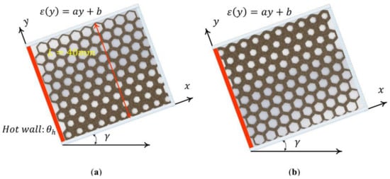
Figure 1.
Latent heat thermal energy storage unit: (a) porosity with a positive gradient (a > 0) and (b) porosity with a negative gradient (a < 0).

Table 1.
Thermophysical properties of the coconut oil and nanoadditives [22,23].
The change of density from solid (920 kg/m3) to liquid (914 kg/m3) is just 0.65%. Thus, coconut oil has a very small density variation. This variation could be important for mechanical issues and may require a small void gap in the enclosure design to allow for liquid expansion during melting. However, the effect of density variation is neglected in the fluid motion and heat transfer model. The size of the 2D enclosure is 40 mm. The left side surface of the enclosure is set at a high constant-temperature of θh, and the other surfaces are insulated. The porosity function is as follows:
where and are the porosities at y = 0 and L, respectively. The average porosity, , can be defined by integrating the porosity all over the domain. The melted nano-enhanced phase change material (NePCM) is considered laminar and Newtonian. In addition, the volume change in the NePCM during the phase change process is assumed to be zero. The enthalpy-porosity technique is employed to simulate melting flow. The balance equations for mass, momentum, and energy are as follows:
where Xi is the ith coordinate such that X1 = x and X1 = y. Vi is the velocity in the ith coordinate.
in which
Since the porosity is a spatial function, the corresponding permeability, i.e., η, is also a spatial variable [24]:
where Ol is the diameter of fiber and Op is computed using the pore density. Considering a local thermal equation for PCM and metal foam, the conservation of energy can be written as follows:
in which
where lnp and snp refer to the liquid and solid NePCMs. cmf introduces the properties of the copper metal foam, and eff denotes the effective properties of the porous medium saturated with NePCM.
The thermal conductivity of the liquid/solid NePCM is defined as the following [25,26]:
where z = (1 − ε)/3. In order to calculate the properties of the mixture of coconut oil and dispersed nanoparticles, the below-expressed relations are employed:
Density:
where np and pp introduce the properties of the NePCM and pure PCM, respectively. na denotes the properties of the nano-additives, and VFna is the nano-additives concentration.
Viscosity:
Thermal expansion coefficient:
Thermal conductivity:
Effective heat capacity:
The following boundary and initial conditions are applied to the problem:
On the hot surface:
On the insulated vertical surfaces:
On the insulated horizontal surfaces:
Initial conditions:
The total energy stored capacity in the NePCM domain during melting flow is expressed as follows:
The first term of the above equation denotes the sensible energy, and the second term shows the latent energy stored in the PCM. The liquid fraction of the NePCM is as follows:
where and are the liquid and solid surface areas of the NePCM. The melting volume fraction (MVF) is normalized to the overal amount of NePCM. Performance of the energy storage unit can be
3. Numerical Approach and Grid Check
The finite element method (FEM) is known as a potent technique for solving partial differential and integral equations. Equations (2), (3) and (5) along with the pertinent initial and boundary conditions are solved by employing user-defined FEM codes. The Galerkin-weighted residual approach is employed to create the weak form of the controlling equations. This method applies the Lagrange finite elements with various orders to obtain the object variables in the non-overlapping zones of the computational region. The weighted mean of the residuals, Rm, while calculating the object variables is zero for the whole domain.
where Wf is the weight function. Nonlinear residual formulas are integrated by utilizing the second-order Gaussian-quadrature technique. The backward differentiation formula (BDF) [27], as an automatic matter, is employed to control the time step. To solve the residual formulas, a Newtonian damping with the value of 0.8 in PARallel DIrect SOlver (PARDISO) is selected. Moreover, the relative tolerance of 10−3 is set for the convergence criteria [28,29,30].
The whole region of NePCM is divided into rectangular subdomains, namely finite elements. To assess an appropriate mesh that can simultaneously ensure the accuracy of the numerical results and lower computational cost, the grid sizes are increased from 125 × 125, 150 × 150, 175 × 175, 200 × 200, and 250 × 250. Figure 2a depicts the structured grid 150 × 150 adopted for the computations. As seen in Figure 2b,c, change in the mesh size induces minimal impact on the variation in MVF and temperature. A mesh size smaller than 125 × 125 cannot capture the phase change interface, and the solver could diverge. Although using a fine mesh can increase the computational cost, a mesh size of 150 × 150 can avoid possible convergence issues. The chosen parameters for this test are L = 50 mm, , , a = 4, , and PPI = 10.
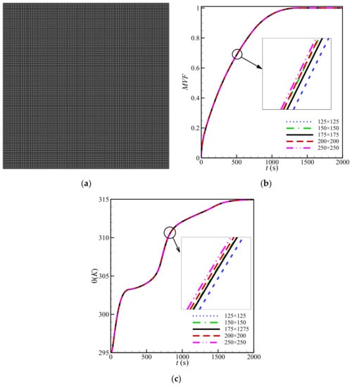
Figure 2.
(a) Structured grid and the variation in (b) MVF and (c) local temperature at the points of location (25 mm and 45 mm) for variants of the uniform mesh when L = 50 mm, , , a = 4, , and pores per inch (PPI) = 10.
To use the present model for further calculation, the model is verified and validated with the numerical and experimental work in [22,31]. In the numerical verification, isotherms and streamlines in an inhomogeneous porous enclosed medium of the work conducted by Xiong et al. [32] and the current model are compared, as illustrated in Figure 3. In this comparative analysis, free convection heat transfer in an enclosure with the inhomogeneous porosity distribution is analyzed. High and low temperatures of θh and θc are imposed on the left and right surfaces of the domain. However, the other walls are adiabatic. In the comparison presented in Figure 3, the porosity distribution is a linear function in y-direction. Herein, the nondimensional parameters of Rayleigh are 104, Darcy 10−1, and Prandtl 6.2. This verification clearly depicts that the present model is in excellent agreement with the computations of the study carried out by Xiong et al. [32]. In the second comparative analysis, the results of the experiments carried out by Al-Jethelah et al. [22] were re-stimulated with our developed model for code validation. In [22], while the other walls of the enclosure were well insulated, the left wall was heated continuously with constant heat flux. The copper foam with high porosity (ε = 0.92) was employed. The permeability of the copper foam calculated using Equation (4) was assessed to be 3.3142 × 10⁻⁷ by the authors. As depicted in Figure 4, the obtained melt fraction of the present model and those presented by [22] are in good agreement, and similar trends for conduction and convection modes could be seen.
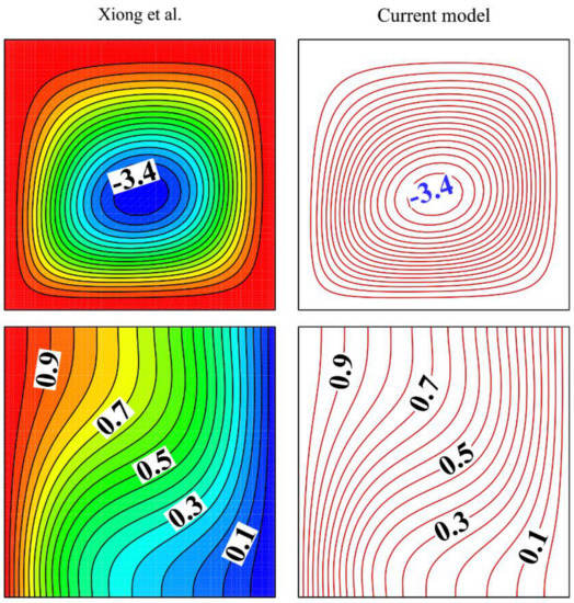
Figure 3.
Isotherms and streamlines in an inhomogeneous porous medium of the work conducted by Xiong et al. [32] and the current model.
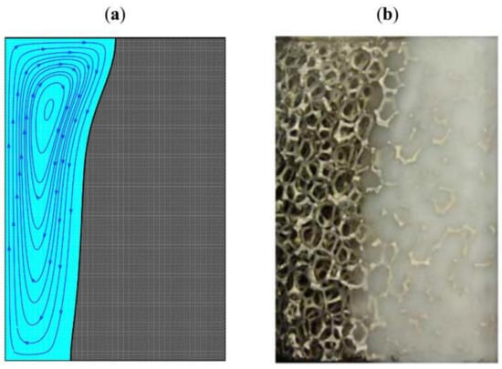
Figure 4.
Melted domains of the phase change material: (a) numerical result of the current model and (b) experimental observation by [22].
4. Results and Discussion
The average porosity (), the volume fraction of the nano-additives (), the gradient of porosity (), the inclination angle of the enclosed medium (), and the pore per inch of the metal matrix () are alterable parameters for the thermal storage design.
Here, an orthogonal table for a combination of parameters is considered, as shown in Table 2. This table searches for the alterable combination of parameter efficiency. The numerical tests were done for each case of Table 2, and the required time for melting of 90% and corresponding stored energy and power are reported. As seen, case 6 of this table shows the minimum 90% charging time of 313 s. Thus, this case is considered the best design. Table 3 shows that the largest melting time is for case 5 with a melting time of 953 s. This case has a maximum porosity of 0.9. Thus, the relative difference between the best case (313 s) and the worst case (935) is 205% compared to the best case (100 × (935 − 313)/313).

Table 2.
L25 orthogonal table corresponding to range and levels of control parameters for y-variation when MVF = 0.9.

Table 3.
The details of 20 test cases for investigation of the impact of design parameters in the melting rate and energy storage when MVF = 0.9.
Twenty more systematic cases were executed, according to Table 3, to explore the influence of volume fraction of nanoparticles, porosity, linear distribution of porosity, and pore size on the storage design’s melting behavior. This table shows that the increase in concentration of nanoparticles reduces the melting time. Growth of the inclination angle or pores density (PPI) slightly raises the melting time, while a rise in porosity notably increases the melting time. The variation in porosity distribution (a) leads to a nonmonotonic variation of melting time.
The results of Table 3 show that the variation in volume fraction of nanoparticles from zero to 4% could change the melting time by 3.4%. The variation of porosity from 0.825 to 0.90 induces 116% changes in the melting time. Alteration of the nonuniform porosity parameter (a) from −4 to 4 could change the melting time by 2.3%. Finally, the variation in inclination angle (γ) and pore density (PPI) changed the melting time by 0.5% and 4.4%, respectively.
The streamlines can be seen in Figure 5. Interestingly, most of the PCM melted in the case εave = 0.8 and at 450 s, while for the case of εave = 0.9 and the same time-step, only about a half of the enclosure melted. The isotherms show almost a linear variation in the enclosure. Here, t = 50 s is the beginning of melting and most of the cavity is solid. Thus as mentioned, the heat transfer is mostly conduction dominant. For low-porosity cases, the isotherms are generally farther from each other than the cases with high porosity. This is since a low porosity means more metal foam and better composite effective thermal conductivity. The lower the composite thermal conductivity, the lower the temperature gradients.
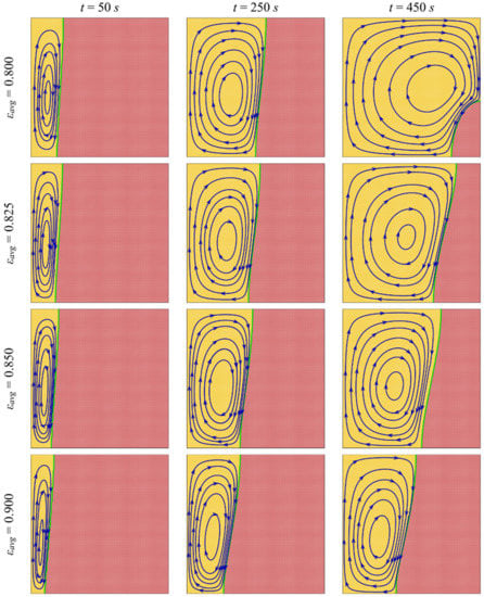
Figure 5.
Stream lines and melting interface (green solid line) at three different times for various average porosities when VFna = 0.01, a = −2, γ = 2π/4, and PPI = 25.
Figure 5 and Figure 6 depict the melting maps and isotherms in the enclosure for various porosity values. The results are reported at three time-points: 50 s, 250 s, and 450 s. The first 50 s could be considered a conduction dominant heat transfer regime. As seen, the increase in porosity reduces the overall molten region. This is since a higher porosity means lower metal foam and smaller composite thermal conductivity. Moreover, for this case, the porosity parameter (a) is negative (a = −2), and hence, as height (y coordinate) increases, the porosity decreases locally. Thus, the amount of metal at the high cavity regions is more and the local composite thermal conductivity is also high. As seen, the top region melted faster than the bottom region. The results are for an inclination angle of π/2, where the gravity vector acts toward the hot wall. The natural convection flow tends to improve the melting heat transfer in the middle of the enclosure due to the direction of the buoyancy force.
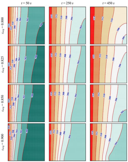
Figure 6.
Isotherm contours at three different times for various average porosities when VFna = 0.01, a = −2, γ = 2π/4, and PPI = 25.
Figure 7 illustrates the MVF and stored energy (ES) in the enclosure for various porosity values. This figure is in agreement with the contours of Figure 5 and Figure 6 showing, that the lower the porosity, the higher the melting rate and stored energy.
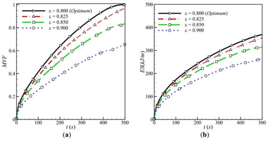
Figure 7.
The effect of various average porosity (a) on the melting volume fraction and (b) energy stored when VFna = 0.01, a = −2, γ = 2π/4, and PPI = 25.
Figure 8 and Figure 9 show the impact of the porosity parameter (a) in the melting map and isotherms. As seen, by variation of a, some degrees of isotherm deflections could be seen. For the cases of a = −4 and −2, the isotherms are close to each other at the bottom and have more distance at the top. This is because, for negative values of a, the porosity is high at the bottom (low composite thermal conductivity). A low composite thermal conductivity leads to high-temperature gradients. In contrast, for the cases with positive a, the behavior is reversed. It should be noted that, for these cases, gravity acts toward the hot wall, and hence, the buoyancy force is perpendicular to the hot wall and tends to melt the PCM mostly from the center. Hence, when a is small, the general impact of the negative and positive values of a on the MVF and ES could be almost the same. When a is large, it could lead to a significant geometrical variation in the melting interface and could change the melting behavior. Figure 10 shows the MVF and ES for various values of a. This figure shows that the variation in a could induce minimal impact on the MVF and stored energy.
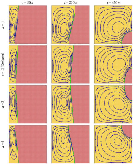
Figure 8.
Stream lines and melting interface (green solid line) at three different times for various porosity parameters (a) when VFna = 0.01, ε = 0.800, γ = 2π/4, and PPI = 25.
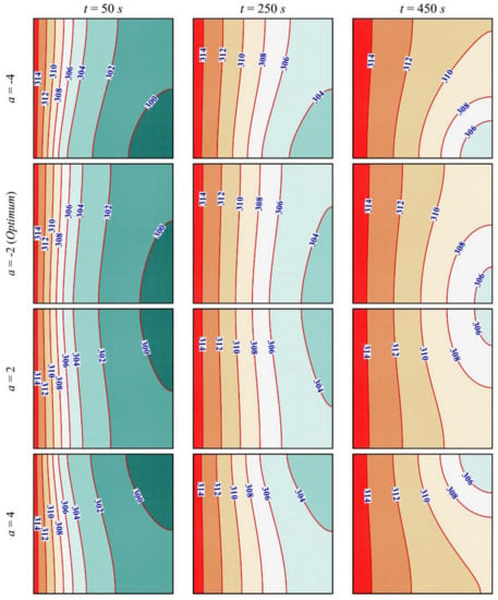
Figure 9.
Isotherm contours at three different times for various porosity parameters (a) when VFna = 0.01, ε = 0.800, γ = 2π/4, and PPI = 25.
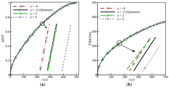
Figure 10.
The effect of various porosity parameters (a) on the melting volume fraction and (b) energy stored when VFna = 0.01, ε = 0.800, γ = 2π/4, and PPI = 25.
The influence of inclination angle (γ) on the melting process is investigated in the contours of Figure 11 and Figure 12. The inclination of the cavity changes the buoyancy forces and the direction of streamlines. For example, for the cases of γ = 0 and π/2, the streamlines are clockwise, while for the cases of γ = 3π/4 and π, the streamlines are counterclockwise.
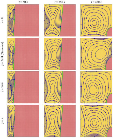
Figure 11.
Stream lines and melting interface (green solid line) at three different times for various inclination angles of the enclosed medium when VFna = 0.01, ε = 0.800, a = −2, and PPI = 25.
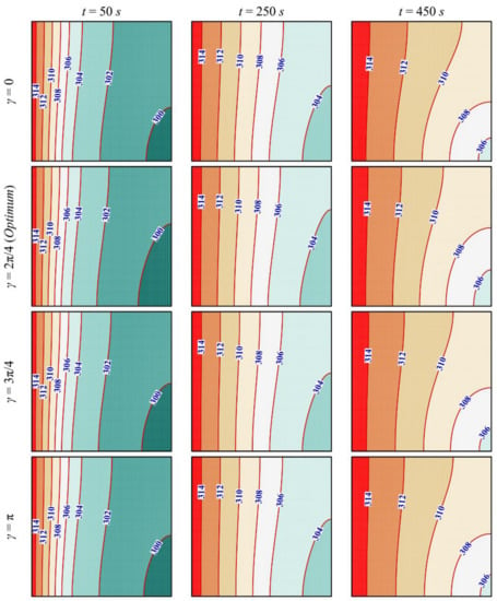
Figure 12.
Isotherm contours at three different times for various inclination angles of the enclosed medium when VFna = 0.01, ε = 0.800, a = −2, and PPI = 25.
Figure 13 is plotted to depict the impact of the inclination angle on the melting fraction and stored energy. These figures show that the inclination angle induces a minimal impact on the meting rate and stored energy. The reason for this is that the convection heat transfer is limited in a porous medium and particularly in a case with low porosity. Thus, the variation in inclination angle, which changes the natural convection flows, could also induce minimal impacts. Maybe using a larger enclosure could pronounce such effects. However, for a large enclosure, the overall melting time would also increase, which could be impractical for fast-charging energy storage systems. The effect of variation in nanoparticle concentration and pores density (PPI) on the melting process was also investigated. However, due to a significant amount of metal foams and minimal importance of natural convection effects, the results showed that the nanoparticles could add minimal impact on the phase change rate. Such graphs were not reported for the sake of brevity.
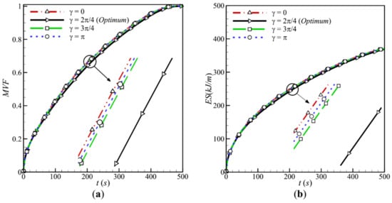
Figure 13.
The effect of various inclination angles of the enclosed medium: (a) on the melting volume fraction and (b) energy stored when VFna = 0.01, ε = 0.800, a = −2, and PPI = 25.
5. Conclusions
5.1. The Key Findings
The flow and heat transfer in an enclosure filled with a nonuniform metal foam was investigated. The porosity was changed in the y-direction using a controlling parameter a, while the average porosity was fixed. The governing equations and phase change properties for phase change heat transfer in the metal foam were introduced in the form of partial differential equations and were solved using the finite element method. The storage unit’s melting behavior was studied for various values of average porosity, nonuniformity parameters, and inclination angles. The presence of metal foams could significantly improve the melting rate. The variation of porosity from 0.825 to 0.9 could change the melting time by 116%
5.2. Practical Significance/Usefulness
The presence of metal foam can improve heat transfer by enhancing the conduction heat transfer mechanism. However, as the melting process advances, the number of liquid PCM rises and natural convection flows can be formed. This is while the presence of a metal foam resists fluid motion and tends to suppress the natural convection flows. The presence of nanoparticles can also improve conduction heat transfer, but they increase the dynamic viscosity of liquid PCM, which acts against the fluid motion. Here, a nonuniform porosity variation was proposed to support the conduction heat transfer mechanism in the early stages of heat trasfer, where the PCM is solid. Then, the porosity can be increased where the natural convection flows commences. It was found that the nonuniformity parameter could change the isotherm and melting behavior in the enclosure. However, due to the configuration of the enclosure, the variation in porosity in the y-direction did not induce a significant impact on the melting rate. The impact of volume fraction of nanoparticles, the pore density, and inclination angles on the melting heat transfer was also small. Indeed, these parameters could impact the natural convection flows directly. This is while the natural convection flows in the metal foam were limited. Hence, the control parameters, which could influence natural convection, could only induce minimal alteration of the final melting process. The impact of each of these design parameters on the melting time was less than 5%.
It can be concluded that the porosity is a major design parameter and should be taken into account for acceleration of melting heat transfer. Then, the heat transfer can be slightly improved by using other methods.
One can also conclude that the porosity variation and using nanoparticles could better impact the melting process for large-scale thermal energy storage systems. In a large-scale system, the molten region can be extended and the distance between the heated surface and solid PCM could be large. Therefore, heat should be conducted through long distances to reach the cold PCM. While there is an extended molten region, the hot liquid PCM can easily move from the hot surface and reach the cold PCM. Thus, in large-scale systems, the natural convection flows could be significant. The large-scale systems were not in the scope of the present research, and hence, they were not investigated here.
In the continuation of this study, some suggestions can be made. As discussed in detail, this study provides the melting process in a copper foam with linear porosity variation in the vertical direction. Moreover, it was assumed that the PCM and metal foam are in local thermal equilibrium. Hence, in an upcoming study, the local thermal nonequilibrium condition can be applied to the copper foam with linear porosity variation. In addition, the porosity variations can be considered nonlinear.
Author Contributions
Conceptualization, M.G. and P.T.; methodology, M.S. (Mohammad Shahabadi) and S.A.M.M.; software, M.S. (Mohammad Shahabadi) and S.A.M.M.; validation, S.A.M.M. and M.S. (Mohammad Shahabadi); formal analysis, M.S. (Mohammad Shahabadi), S.A.M.M., and O.Y.; investigation, M.G., M.S. (Mohammad Shahabadi), S.A.M.M., M.S. (Mikhail Sheremet), O.Y., P.T., and W.Y.; resources, W.Y.; writing—original draft preparation, M.G., M.S. (Mohammad Shahabadi), S.A.M.M., M.S. (Mikhail Sheremet), O.Y., P.T., and W.Y.; writing—review and editing, M.G., M.S. (Mohammad Shahabadi), S.A.M.M., M.S. (Mikhail Sheremet), O.Y., P.T., and W.Y.; visualization, M.S. (Mohammad Shahabadi) and S.A.M.M.; supervision, M.G. All authors have read and agreed to the published version of the manuscript.
Funding
This research received no external funding.
Institutional Review Board Statement
Not applicable.
Informed Consent Statement
Not applicable.
Data Availability Statement
Data is contained within the article.
Conflicts of Interest
The authors declare no conflict of interest.
Nomenclature
| Latin symbols | |
| a | porosity slop |
| A* | mushy constant, 5 × 10⁵ |
| Alnp | liquid surface area of the NePCM (m2) |
| Asnp | solid surface area of the NePCM (m2) |
| b | value of porosity at y = 0, ε0 |
| Cp | heat capacity (J/(kg.K) |
| ES | total stored energy (kJ/m) |
| gi | gravity in the ith coordinate (m/s2) |
| K | thermal conductivity (W/m.K) |
| L | size of the latent heat thermal energy storage unit (cm) |
| llpp | latent heat of pure PCM (kJ/kg) |
| MVF | liquid fraction of the NePCM |
| Ol | diameter of fiber (m) |
| Op | diameter of pore (m) |
| p | liquid pressure (Pa) |
| P | performance of the energy storage unit (kW/m) |
| PPI | pore per inch |
| Rm | weighted mean of the residuals |
| VFna | nano-additives concentration |
| Vi | velocity in the ith coordinate (m/s) |
| Wf | the weight function |
| Xi | ith coordinate (m) |
| Greek symbols | |
| β | thermal expansion coefficient of PCM (1/K) |
| γ | inclination angle of the unit (rad) |
| δθmel | melting temperature window of the pure PCM (K) |
| ε | porosity |
| ε0 | porosity at y = 0 |
| εL | porosity at y = L |
| θ | temperature (K) |
| η | permeability (m2) |
| μ | dynamic viscosity (Pa.s) |
| ρ | density (kg/m3) |
| Subscripts | |
| ave | average |
| eff | effective characteristics of the copper foam and NePCM |
| lnp | liquid nano-enhanced phase change material |
| mel | melting |
| cmf | copper metal foam |
| na | dispersed nano-additives |
| np | nano-enhanced phase change material |
| pp | pure PCM |
| snp | solid nano-enhanced phase change material |
References
- Sadeghianjahromi, A.; Wang, C.-C. Heat transfer enhancement in fin-and-tube heat exchangers—A review on different mechanisms. Renew. Sustain. Energy Rev. 2021, 137, 110470. [Google Scholar] [CrossRef]
- Mousa, M.H.; Miljkovic, N.; Nawaz, K. Review of heat transfer enhancement techniques for single phase flows. Renew. Sustain. Energy Rev. 2021, 137, 110566. [Google Scholar] [CrossRef]
- Mahdi, J.M.; Lohrasbi, S.; Nsofor, E.C. Hybrid heat transfer enhancement for latent-heat thermal energy storage systems: A review. Int. J. Heat Mass Transf. 2019, 137, 630–649. [Google Scholar] [CrossRef]
- Ryu, S.; Han, J.; Kim, J.; Lee, C.; Nam, Y. Enhanced heat transfer using metal foam liquid supply layers for micro heat spreaders. Int. J. Heat Mass Transf. 2017, 108, 2338–2345. [Google Scholar] [CrossRef]
- Feng, S.; Li, F.; Zhang, F.; Lu, T.J. Natural convection in metal foam heat sinks with open slots. Exp. Therm. Fluid Sci. 2018, 91, 354–362. [Google Scholar] [CrossRef]
- Astanina, M.; Sheremet, M.; Mahabaleshwar, U.S.; Singh, J. Effect of Porous Medium and Copper Heat Sink on Cooling of Heat-Generating Element. Energies 2020, 13, 2538. [Google Scholar] [CrossRef]
- Liang, L.; Diao, Y.; Zhao, Y.; Wang, Z.; Bai, F. Numerical and experimental investigations of latent thermal energy storage device based on a flat micro-heat pipe array–metal foam composite structure. Renew. Energy 2020, 161, 1195–1208. [Google Scholar] [CrossRef]
- Shen, L.; Xu, S.; Bai, Z.; Wang, Y.; Xie, J. Experimental study on thermal and flow characteristics of metal foam heat pipe radiator. Int. J. Therm. Sci. 2021, 159, 106572. [Google Scholar] [CrossRef]
- Delgado-Diaz, W.; Stamatiou, A.; Maranda, S.; Waser, R.; Worlitschek, J. Comparison of Heat Transfer Enhancement Techniques in Latent Heat Storage. Appl. Sci. 2020, 10, 5519. [Google Scholar] [CrossRef]
- Mahian, O.; Kolsi, L.; Amani, M.; Estellé, P.; Ahmadi, G.; Kleinstreuer, C.; Marshall, J.S.; Siavashi, M.; Taylor, R.A.; Niazmand, H.; et al. Recent advances in modeling and simulation of nanofluid flows-Part I: Fundamentals and theory. Phys. Rep. 2019, 790, 1–48. [Google Scholar] [CrossRef]
- Mahian, O.; Kolsi, L.; Amani, M.; Estellé, P.; Ahmadi, G.; Kleinstreuer, C.; Marshall, J.S.; Taylor, R.A.; Abu-Nada, E.; Rashidi, S.; et al. Recent advances in modeling and simulation of nanofluid flows–Part II: Applications. Phys. Rep. 2019, 791, 1–59. [Google Scholar] [CrossRef]
- Xu, H.; Xing, Z. The lattice Boltzmann modeling on the nanofluid natural convective transport in a cavity filled with a porous foam. Int. Commun. Heat Mass Transf. 2017, 89, 73–82. [Google Scholar] [CrossRef]
- Qi, C.; Tang, J.; Ding, Z.; Yan, Y.; Guo, L.; Ma, Y. Effects of rotation angle and metal foam on natural convection of nanofluids in a cavity under an adjustable magnetic field. Int. Commun. Heat Mass Transf. 2019, 109, 104349. [Google Scholar] [CrossRef]
- Xu, H.; Xing, Z.; Vafai, K. Analytical considerations of flow/thermal coupling of nanofluids in foam metals with local thermal non-equilibrium (LTNE) phenomena and inhomogeneous nanoparticle distribution. Int. J. Heat Fluid Flow 2019, 77, 242–255. [Google Scholar] [CrossRef]
- Ghaneifar, M.; Arasteh, H.; Mashayekhi, R.; Rahbari, A.; Mahani, R.B.; Talebizadehsardari, P. Thermohydraulic analysis of hybrid nanofluid in a multilayered copper foam heat sink employing local thermal non-equilibrium condition: Optimization of layers thickness. Appl. Therm. Eng. 2020, 181, 115961. [Google Scholar] [CrossRef]
- Yang, L.; Jin, X.; Zhang, Y.; Du, K. Recent development on heat transfer and various applications of phase-change materials. J. Clean. Prod. 2021, 287, 124432. [Google Scholar] [CrossRef]
- Bondareva, N.S.; Buonomo, B.; Manca, O.; Sheremet, M.A. Heat transfer inside cooling system based on phase change material with alumina nanoparticles. Appl. Therm. Eng. 2018, 144, 972–981. [Google Scholar] [CrossRef]
- El Idi, M.M.; Karkri, M. Heating and cooling conditions effects on the kinetic of phase change of PCM embedded in metal foam. Case Stud. Therm. Eng. 2020, 21, 100716. [Google Scholar] [CrossRef]
- Yang, X.; Wang, X.; Liu, Z.; Guo, Z.; Jin, L.; Yang, C. Influence of aspect ratios for a tilted cavity on the melting heat transfer of phase change materials embedded in metal foam. Int. Commun. Heat Mass Transf. 2021, 122, 105127. [Google Scholar] [CrossRef]
- Iasiello, M.; Mameli, M.; Filippeschi, S.; Bianco, N. Metal foam/PCM melting evolution analysis: Orientation and morphology effects. Appl. Therm. Eng. 2021, 187, 116572. [Google Scholar] [CrossRef]
- Zhang, X.; Su, G.; Lin, J.; Liu, A.; Wang, C.; Zhuang, Y. Three-dimensional numerical investigation on melting performance of phase change material composited with copper foam in local thermal non-equilibrium containing an internal heater. Int. J. Heat Mass Transf. 2021, 170, 121021. [Google Scholar] [CrossRef]
- Al-Jethelah, M.; Ebadi, S.; Venkateshwar, K.; Tasnim, S.; Mahmud, S.; Dutta, A. Charging nanoparticle enhanced bio-based PCM in open cell metallic foams: An experimental investigation. Appl. Therm. Eng. 2019, 148, 1029–1042. [Google Scholar] [CrossRef]
- Choi, S.-K.; Kim, S.-O.; Lee, T.-H. Computation of the Natural Convection of Nanofluid in a Square Cavity with Homogeneous and Nonhomogeneous Models. Numer. Heat Transf. Part A Appl. 2013, 65, 287–301. [Google Scholar] [CrossRef]
- Nield, D.A.; Bejan, A. Convection in Porous Media; Springer: Berlin/Heidelberg, Germany, 2017. [Google Scholar]
- Mesalhy, O.; Lafdi, K.; Elgafy, A.; Bowman, K. Numerical study for enhancing the thermal conductivity of phase change material (PCM) storage using high thermal conductivity porous matrix. Energy Convers. Manag. 2005, 46, 847–867. [Google Scholar] [CrossRef]
- Zheng, H.; Wang, C.; Liu, Q.; Tian, Z.; Fan, X. Thermal performance of copper foam/paraffin composite phase change material. Energy Convers. Manag. 2018, 157, 372–381. [Google Scholar] [CrossRef]
- Reyes, J.C.D.L.; Andrade, S.G. A combined BDF-semismooth Newton approach for time-dependent Bingham flow. Numer. Methods Partial. Differ. Equ. 2011, 28, 834–860. [Google Scholar] [CrossRef]
- Schenk, O.; Gärtner, K. Solving unsymmetric sparse systems of linear equations with PARDISO. Future Gener. Comput. Syst. 2004, 20, 475–487. [Google Scholar] [CrossRef]
- Wriggers, P. Nonlinear Finite Element Methods; Springer: Berlin/Heidelberg, Germany, 2008. [Google Scholar]
- Verbosio, F.; De Coninck, A.; Kourounis, D.; Schenk, O. Enhancing the scalability of selected inversion factorization algorithms in genomic prediction. J. Comput. Sci. 2017, 22, 99–108. [Google Scholar] [CrossRef]
- Xiong, Q.; Poor, H.Z.; Izadi, M.; Assareh, E. Natural heat exchange in inhomogeneous porous medium using linear and quadratic porosity distribution. Int. J. Therm. Sci. 2021, 161, 106731. [Google Scholar] [CrossRef]
- Feng, Y.; Li, H.; Li, L.; Bu, L.; Wang, T. Numerical investigation on the melting of nanoparticle-enhanced phase change materials (NEPCM) in a bottom-heated rectangular cavity using lattice Boltzmann method. Int. J. Heat Mass Transf. 2015, 81, 415–425. [Google Scholar] [CrossRef]
Publisher’s Note: MDPI stays neutral with regard to jurisdictional claims in published maps and institutional affiliations. |
© 2021 by the authors. Licensee MDPI, Basel, Switzerland. This article is an open access article distributed under the terms and conditions of the Creative Commons Attribution (CC BY) license (http://creativecommons.org/licenses/by/4.0/).