Abstract
A modeling of a turbo air compressor system (TACS), with a multi-level inverter for driving variable speed, combining an electrical model of an electric motor drive system (EMDS) and a mechanical model of a turbo air compressor, is essential to accurately analyze dynamics characteristics. Compared to the mechanical model, the electrical model has a short sampling time due to the high frequency switching operation of the numerous power semiconductors inside the multi-level inverter. This causes the problem of increased computational time for dynamic characteristics analysis of TACS. To solve this problem, the conventional model of the multi-level inverter has been proposed to simplify the switching operation of the power semiconductors, however it has low accuracy because it does not consider pulse width modulation (PWM) operation. Therefore, this paper proposes an improved modeling of the multi-level inverter for TACS to reduce computational time and improve the accuracy of electrical and mechanical responses. In order to verify the reduced computational time of the proposed model, the conventional model using the simplified model is compared and analyzed using an electronic circuit simulation software PSIM. Then, the improved accuracy of the proposed model is verified by comparison with the experimental results.
1. Introduction
Recently a variable speed drive (VSD) for electric motors that improves energy efficiency has drawn tremendous interest within the power industry. Simple and classical 2-level inverters for VSD have the disadvantages of complex circuit configuration and difficulty in controlling, requiring high power and medium voltage [1,2,3]. Moreover, overvoltage stress is generated in the motor due to the high frequency pulse width modulation (PWM) switching of the 2-level inverters [4]. To solve this problem, an analog filler is added to the output terminal of the 2-level inverter to suppress overvoltage, but there is a disadvantage of increasing the volume of the system [5].
Multi-level inverters have advantages such as reduced overvoltage and reduced total harmonic distortion due to the high switching frequency operation [6,7,8]. In particular, the multi-level inverter can operate medium voltage and high voltage induction motors, and is applied to large air compressor systems such as screw compressors and centrifugal turbo compressors. Centrifugal turbo air compressors have high operating efficiency, but have a narrow operating range of 70% to 100% [9].
A turbo air compressor system (TACS) consists of a centrifugal turbo compressor for air compression and an electric motor drive system (EMDS) for power transmission to the compressor. In order to improve the efficiency of TACS and expand the operating range, the variable speed drive (VSD) of the motor driven by the multi-level inverter and an inlet guide valve (IGV) control to modulate the operating range are applied [9,10]. The combination of VSD and IGV control should be verified by dynamic characteristics simulation as it may cause system instability due to control variable error, and surge and choke phenomenon [11].
For accurate dynamics characteristics analysis, it is necessary to implement the TACS model that considers the mechanical model of the centrifugal turbo compressor of the TACS and the electrical model of the EMDS [12]. Compared with the mechanical model, the electrical model requires a short sampling time because of the multi-level inverter that performs the high frequency switching operation, so there is a problem that the computational time for analysis becomes longer [13]. To solve this problem, [12] proposed an average model of the multilevel inverter for the TACS, which improved the simplified model of a three-phase inverter. However, the proposed conventional model has a problem of low accuracy of response characteristics because it did not take into account the PWM operation. Therefore, this paper proposes an improved modeling of the multi-level inverter for TACS to reduce the computational time and improve the accuracy of the electrical and mechanical responses. Compared to the conventional model, the proposed model of the multi-level inverter is not complicated, and their parameters are easy to extract. The presented approach enables realizing the simulation of the overall TACS with satisfactory accuracy. Simulated results were compared with experimental results to confirm the accuracy of the proposed model. Models presented in this paper were developed and validated using a PSIM simulator, however, the proposed model solution may be adapted without significant modifications to other circuit simulators, e.g., MATLAB, POWERSIM, PSpice, etc. The proposed modeling approach may be successfully used for the evaluation of control variable selection, system stability, and energy saving analysis for TACS.
2. Configuration of TACS
Figure 1 shows the configuration of TACS. TACS is classified into a mechanical model and an electrical model. The mechanical model is a turbo air compressor and is composed of the helical gear, IGV, blow of valve, control valve, and stage impellers. The electrical model is the EMDS, which consists of an induction motor and a multi-level inverter. Table 1 and Table 2 show the specifications of TACS and EMDS. With a pressure of 8 bar, the rated flow is 10,000 m3/h, the shaft rotation speed is 3600 rpm, and the rated mechanical power of the shaft is 848.9 kW. The operating range is 70 to 100% with VSD, and 40 to 100% with VSD and IGV control. Since the input voltage is 6.6 KV, the topology of the multi-level inverter was selected as the 11-level cascaded half bridge (CHB) inverter [10].
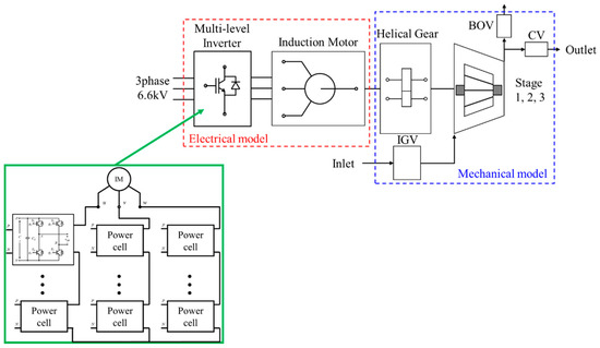
Figure 1.
Configuration of turbo air compressor system (TACS).

Table 1.
Specifications of TACS.
Table 2.
Specifications of electric motor drive system (EMDS).
3. Model of TACS
3.1. Mechanical Model
The turbo air compressor can be modeled using compressor maps derived through the computational fluid dynamics (CFD) analysis. The mechanical model of the turbo air compressor can be expressed by the corrected air flow rate mcorr, pressure ratio PR, and corrected rotational speed Ncorr as follows [9]:
where m1 is the air flow rate, T1 is the temperature of inlet, p1 and p2 are the pressures of the inlet and outlet. The compressed air flow rate according to the IGV angle can be expressed as follows [12]:
where m1max is the compressed air flow rate when the IGV angle is maximum, VACF is the angle correction factor of the IGV, and δmax and δ are the maximum angle and IGV angle. The shaft power of an electric motor in an air compressor can be expressed as follows [12]:
where cp is the specific heat at constant pressure and T2 is the temperature of outlet. The shaft power of the mechanical model can be used to apply torque to the electrical model.
mcorr = (m1√T1/p1)/(m1√T1/p1)nom
PR = (p2/p1)/(p2/p1)nom
Ncorr = (n/√T1)/(n/√T1)nom
m1 = m1max [1 − VACF(δmax − δ)]
Pc = m1cp(T1 − T2)
3.2. Electrical Model
The torque equation and output power equation of the induction motor using dq-axis transformation are as follows [14]:
where Lm is the magnetizing inductance, ids and iqs are the d-axis current and q-axis current of the stator, idr and iqr are the d-axis current and q-axis current of the rotor, ωm is the mechanical angular speed of the rotor and Tm is mechanical torque which is equal to the electrical torque Te. Compared to the induction motor model using the three-phase voltage equation, the dq-axis voltage equation is mathematically simpler and the computational time can be shortened [12].
Te = (P/2)(3/2)Lm(iqsidr − idsiqr)
Pm = ωmTm (Tm = Te)
The detailed model of the 11-level CHB inverter can be implemented with multi-carrier modulation using PWM [15,16]. The multi carrier modulation switches the power semiconductor device through comparison of a carrier wave and a modulated wave. The number of the power cells per phase of the 11-level CHB inverter can be expressed as follows:
where m is the number of level of inverter. In the case of the 11-level CHB inverter in the simulation software PSIM environment, there is a problem that a total of 60 power semiconductor device models are switched which is increase the computational time.
h = 1/2(m − 1)
To simplify the semiconductors, Figure 2a shows the flow chart of the conventional model to shorten the long computational time of the detailed model in the PSIM simulator due to the switching operation of the inverter. For the conventional model, when the reference speed nref is inputted, the electrical angle θ of the induction motor and the magnitude V of the modulated wave are calculated to generate three-phase modulated waves vma, vmb, vmc. If the level k corresponding to the switching operation is 1 and 0 < vma, vmb, vmc ≤ k/h, the three phase modulated waves are equal to nref. If k is not 1 and is (k − 1)/h < | vma, vmb, vmc| ≤ k/h, vma, vmb, vmc are equal to k/h. Finally, Sign(vma,vmb,vmc) are input to the output voltage vo(a,b,c,). This flow chart simplifies the operation of the semiconductors, but the PWM operation is not considered.
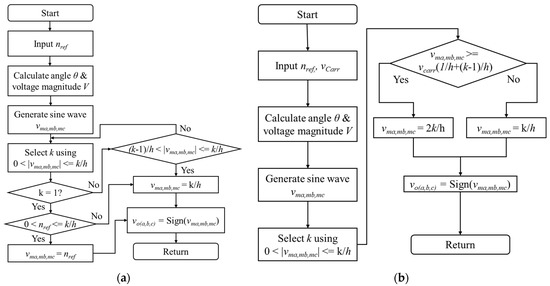
Figure 2.
Comparison of switching operation flow charts. (a) Conventional model; (b) proposed model.
To consider the PWM operation, Figure 2b shows the flow chart of the proposed model to improve the accuracy. For the proposed model, the procedure for selecting k is the same as for the conventional model. In the next step, if vma, vmb, vmc are greater than or equal to vcarr(1/h + (k − 1)/h), vma, vmb, vmc are equal to the 2k/h. If vma, vmb, vmc are less than vcarr(1/h + (k − 1)/h), vma, vmb, vmc are equal to the k/h. Finally, Sign(vma,vmb,vmc) are input to the output voltage vo(a,b,c). The added procedure of the proposed model includes PWM operation of the detailed model so that the response characteristics of the electrical model can be improved.
4. Verification
4.1. Simulation Results
To verify the validity of proposed model (P), the simulation results of response characteristics were derived comparing the detailed model (D) and the conventional model (C).
Figure 3 shows the comparison of dynamic characteristics at the initial startup of EMDS. Compared to the detailed model, the conventional model is the phase u voltage waveform of the inverter that PWM operation does not take account, but the proposed model can confirm the same voltage waveform. For the response of the motor speed, the conventional model has a large speed pulsation and a long pulsation period, but the proposed model can confirm the same response characteristics. For the responses of the three phase currents and the output torque, the conventional model has the different responses from the large overshoots, but the proposed model shows the same response as the detailed model.
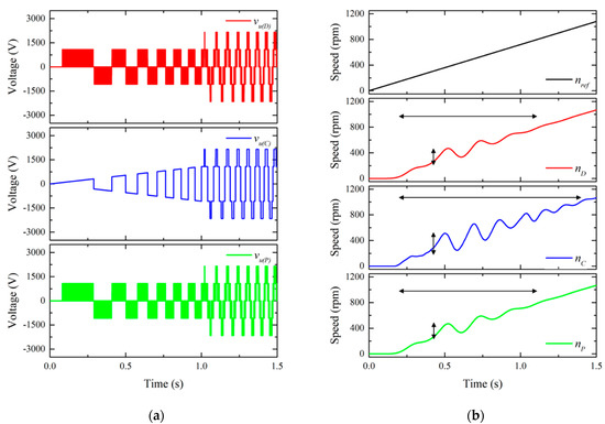
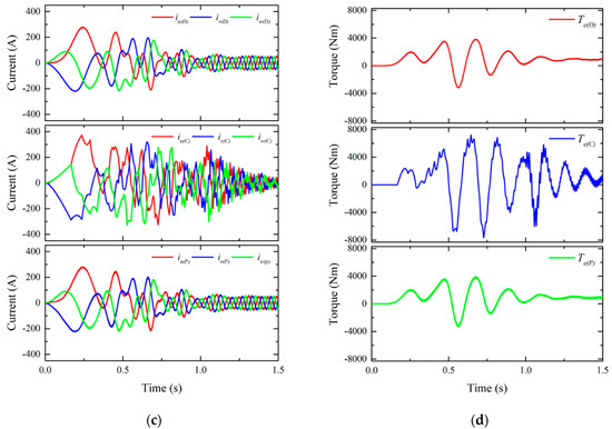
Figure 3.
Comparison of dynamic characteristics at initial startup of EMDS. (a) Phase u voltage; (b) Motor speed; (c) Three phase currents; (d) Output torque.
When the rated load torque is applied 5.5 s after reaching the rated speed, Figure 4 shows the comparison of dynamic characteristics. Compared with the speed response of the detailed model, the conventional model has a large first undershoot and a slow response. The proposed model can confirm the same speed response as the detailed model. For the responses of the three phase currents, the conventional model has different responses from the pulsation of the current peak values, but the proposed model shows the same response as the detailed model. For the output torque, the proposed model has the same response as the detailed model except for the torque ripple.
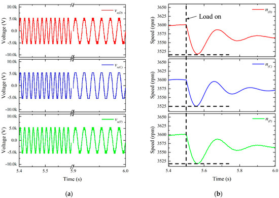
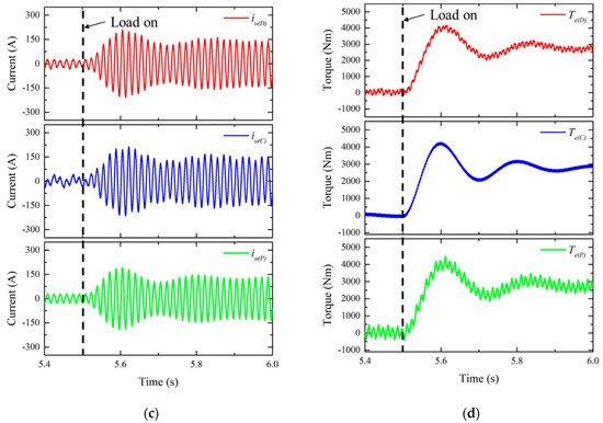
Figure 4.
Comparison of dynamic characteristics at rated speed and rated load torque. (a) Phase u voltage; (b) Motor Speed; (c) Phase u currents; (d) Output Torque.
Figure 5 shows the fast Fourier transform (FFT) results of phase u current at rated speed and rated load torque. In the conventional model, the 7th and 13th harmonics are large, but the proposed model contains similar harmonics to the detailed model.
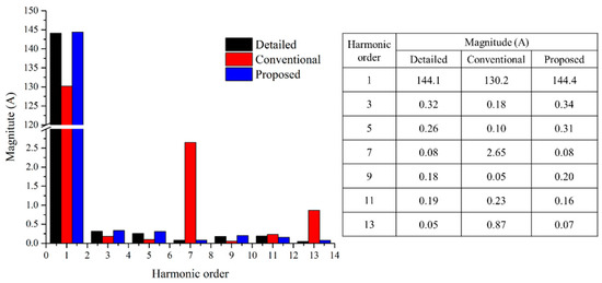
Figure 5.
FFT results of phase u current at rated speed and rated load torque.
Figure 6 shows the comparison of dynamic characteristics at deceleration and acceleration. Compared with the detailed model and the proposed model, the conventional model has a difference in speed response, and has a different torque response due to the harmonic content of the phase u current.
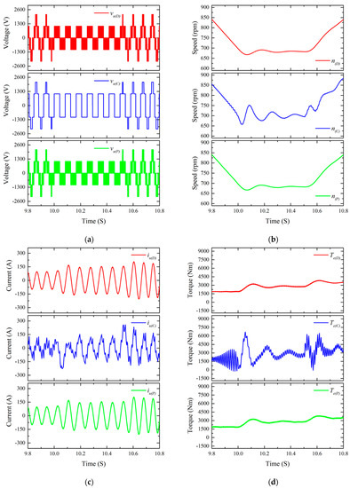
Figure 6.
Comparison of dynamic characteristics at deceleration and acceleration. (a) Phase u voltage; (b) Motor speed; (c) Phase u current; (d) Output torque.
Figure 7 shows the comparison of dynamic characteristics according to speed variation. It can be seen that the power waveform of the conventional model differs from the detailed model and the proposed model due to different speed and phase current responses. Table 3 shows the comparison of the peak current values for each point in Figure 7. It can be seen that the peak current values of the proposed model are similar to that of the detailed model than the conventional model. As a result, the proposed model has successfully improved the accuracy of the conventional model.
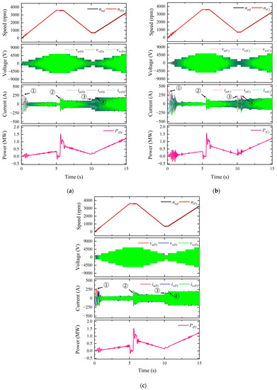
Figure 7.
Comparison of dynamic characteristics according to speed variation. (a) Detailed model; (b) Conventional model; (c) Proposed model.
Table 3.
Comparison of peak current values by points.
Table 4 shows the comparison of the computation time according to the speed variation. The computational time of the proposed model is 7 s, which is the same as the conventional model. As a result, the accuracy of proposed model is improved and the same computational time is secured compared to the conventional model.
Table 4.
Comparison of computational time according to speed variation.
4.2. Experimental Results
Figure 8 shows the experimental setup for TACS as shown in Figure 1. The turbo air compressor is designed based on the specifications in Table 1. The rated specifications of induction motor are 1050 kW, 6600 V and 107.2 A. The topology of the multi-level inverter is 6600 V, 1500 KVA 11-level CHB using Insulated gate bipolar transistor (IGBT). To measure the power consumption of TACS, voltage and current sensors were installed at the 3-phase input terminals of the inverter and the power was calculated using a power meter.
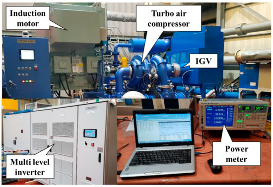
Figure 8.
Experimental setup for TACS.
The test was performed by adjusting VSD and IGV under the same load conditions (ACC, L1, L2, L3, L4, DE: Acceleration, 100%, 98%, 96%, 10%, Deceleration) as the simulation. Figure 9 shows powers comparison of the experimental result, conventional model and proposed model. In ACC, the values of the first power overshoot are 304 kW, 463 kW, and 356 kW. In L1, the average values of the powers are 105 kW, 82 kW, and 104 kW. The reason for the difference in values is the result according to whether or not PWM operation is applied, such as the phase current of point 4 in Figure 7. Compared with the conventional model, the differences in power values of the proposed model are reduced to 107 kW and 22 kW, respectively. In Figure 7b, the power ripple of the conventional model is larger than the experimental result as shown in the FFT result in Figure 5. The proposed model has reduced power ripple compared to the previous model. As a result, the accuracy of the proposed model was improved compared with the conventional model.
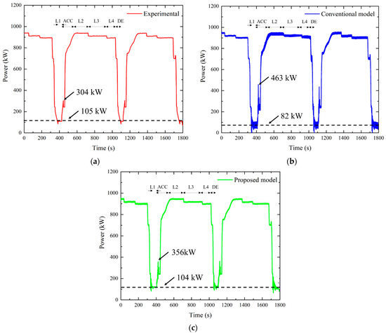
Figure 9.
Powers comparison. (a) Experimental; (b) Conventional model; (c) Proposed model.
In Table 5, compared with the kilowatt hour of the experimental result, the error rates of the conventional model and the proposed model are 2.1% and 0.4%, respectively. The computational time is 14 min for both the conventional model and the proposed model. The effectiveness of the proposed model to reduce the computational time and improve the accuracy was verified.
Table 5.
Comparison of kilowatt hours and computational times.
5. Conclusions
An accurate dynamic simulation of TACS consisting of the mechanical model and the electrical model requires a very long calculation time due to the PWM operation of numerous power semiconductor models inside the multi-level inverter of TACS. To solve this problem, the conventional model simplified the switching operation of the power semiconductors of the multi-level inverter to shorten the computational time, however there was a problem with low accuracy of response characteristics because the PWM operation was not considered. The proposed modeling approach with PWM operation may be successfully applied in TACS simulation. The procedure of model implementation is simple and has accurate response characteristics. In addition, since the same fast computational time as the conventional model is secured, it will be effective in selecting control variables to ensure TACS stability and analyzing the energy savings of the system. The accuracy obtained enables using the proposed modeling approach as a useful tool dedicated to the evaluation of the combination control with VSD and IGV.
Funding
This work was supported by the Korea Institute of Energy Technology Evaluation and Planning (KETEP) grant funded by the Korea government (MOTIE) (20182010106640, Energy saving 1000 HP VSD turbo air compressor).
Institutional Review Board Statement
Not applicable.
Informed Consent Statement
Not applicable.
Data Availability Statement
Not applicable.
Conflicts of Interest
The authors declare no conflict of interest.
References
- Hammond, P.W. A new approach to enhance power quality for medium voltage AC drives. IEEE Trans. Ind. Appl. 1997, 33, 202–208. [Google Scholar] [CrossRef]
- Meynard, T.A.; Foch, H. Multi-level conversion: High voltage choppers and voltage-source inverters. In Proceedings of the PESC’92 Record, 23rd Annual IEEE Power Electronics Specialists Conference, Toledo, Spain, 29 June–3 July 1992; pp. 397–403. [Google Scholar] [CrossRef]
- Lai, J.S.; Peng, F.Z. Multilevel converters-a new breed of power converters. IEEE Trans. Ind. Appl. 1996, 32, 509–517. [Google Scholar] [CrossRef]
- Kim, S.A.; Hong, K.P.; Lee, S.K.; Kang, G.H. Analysis of output characteristics of 6.6KV multi-level inverter according to cable specification. J. KNST 2019, 2, 55–60. [Google Scholar] [CrossRef]
- Steinke, J.K. Use of an LC filter to achieve a motor-friendly performance of the PWM voltage source inverter. IEEE Trans. Energy Convers. 1999, 14, 649–654. [Google Scholar] [CrossRef]
- Khoucha, F.; Lagoun, S.M.; Marouani, K.; Kheloui, A.; Benbouzid, M.E.H. Hybrid cascaded H-bridge multilevel-inverter induction-motor-drive direct torque control for automotive applications. IEEE Trans. Ind. Electron. 2009, 57, 892–899. [Google Scholar] [CrossRef]
- Nallamekala, K.K.; Sivakumar, K. A fault-tolerant dual three-level inverter configuration for multipole induction motor drive with reduced torque ripple. IEEE Trans. Ind. Electron. 2015, 63, 1450–1457. [Google Scholar] [CrossRef]
- Rodriguez, J.; Lai, J.S.; Peng, F.Z. Multilevel inverters: A survey of topologies, controls, and applications. IEEE Trans. Ind. Electron. 2002, 49, 724–738. [Google Scholar] [CrossRef]
- Bentaleb, T.; Cacitti, A.; De Franciscis, S.; Garulli, A. Multivariable control for regulating high pressure centrifugal compressor with variable speed and IGV. In Proceedings of the 2014 IEEE Conference on Control Applications, Juan Les Antibes, France, 8–10 October 2014; pp. 486–491. [Google Scholar] [CrossRef]
- Saidur, R.; Mekhilef, S.; Ali, M.B.; Safari, A.; Mohammed, H.A. Applications of variable speed drive (VSD) in electrical motors energy savings. Renew. Sustain. Energy Rev. 2012, 16, 543–550. [Google Scholar] [CrossRef]
- Jung, M.; Han, J.; Yu, S. Dynamic model of centrifugal compressor for prediction of surge evolution and performance variations. Trans. Korean Soc. Mech. Eng. B 2016, 40, 297–304. [Google Scholar] [CrossRef]
- Kim, S.A.; Hong, K.P. Development of average model to analysis dynamic characteristics of variable speed driven turbo air compressor system with multi level inverter. Trans. Korean Inst. Electr. Eng. 2020, 69, 1200–1207. [Google Scholar] [CrossRef]
- Ku, H.K.; Kwak, K.K.; Kim, J.M. A study integrated-power-system simulation model of all-electric-ship. Trans. Korean Inst. Power Electron. 2015, 20, 45–50. [Google Scholar] [CrossRef][Green Version]
- Krause, P.C.; Wasynczuk, O.; Sudhoff, S.D.; Pekarek, S. Analysis of Electric Machinery and Drive Systems; IEEE Press: New York, NY, USA, 2002; p. 2. [Google Scholar] [CrossRef]
- Prasad, K.N.V.; Kumar, G.R.; Kiran, T.V.; Narayana, G.S. Comparison of different topologies of cascaded H-Bridge multilevel inverter. In Proceedings of the 2013 International Conference on Computer Communication and Informatics, Coimbatore, India, 4–6 January 2013; pp. 1–6. [Google Scholar] [CrossRef]
- Rao, S.N.; Kumar, D.A.; Babu, C.S. Implementation of cascaded based reversing voltage multilevel inverter using multi carrier modulation strategies. Int. J. Power Electron. Dri. Syst. 2018, 9, 220–230. [Google Scholar] [CrossRef]
Publisher’s Note: MDPI stays neutral with regard to jurisdictional claims in published maps and institutional affiliations. |
© 2021 by the author. Licensee MDPI, Basel, Switzerland. This article is an open access article distributed under the terms and conditions of the Creative Commons Attribution (CC BY) license (http://creativecommons.org/licenses/by/4.0/).