
Multi-Criteria Studies and Assessment Supporting the Selection of Locations and Technologies Used in CO2-EGS Systems

 ,
,  ,
,  ,
,  , , ,
, , ,
Abstract
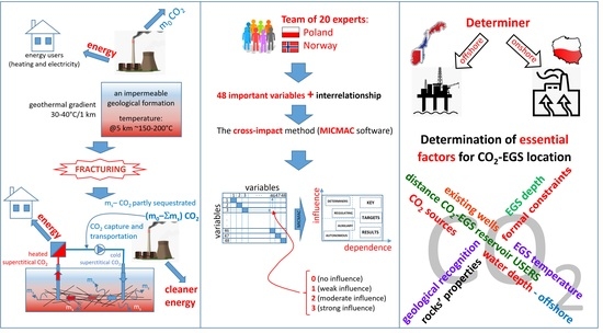
1. Introduction
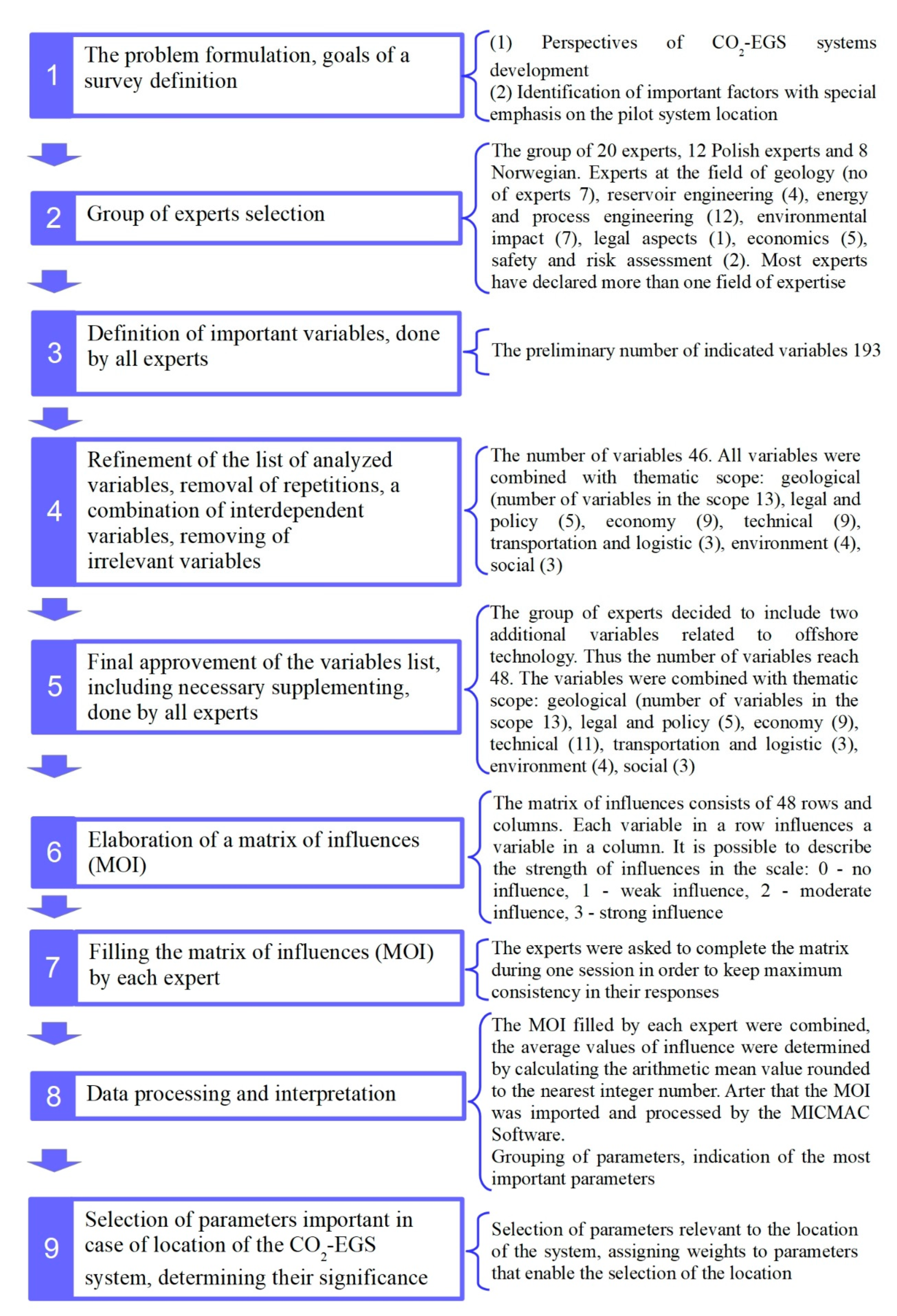
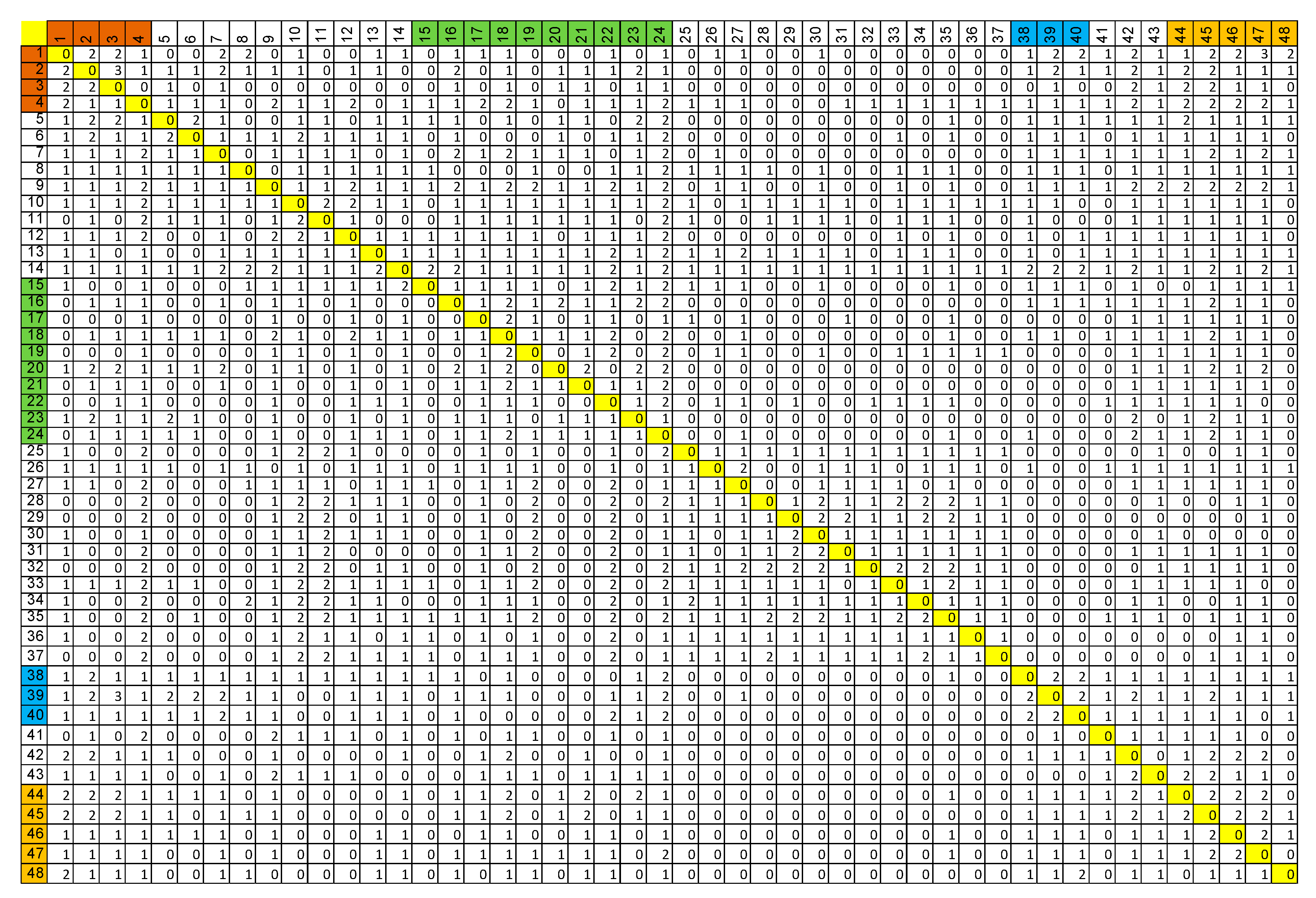
2. Method Description
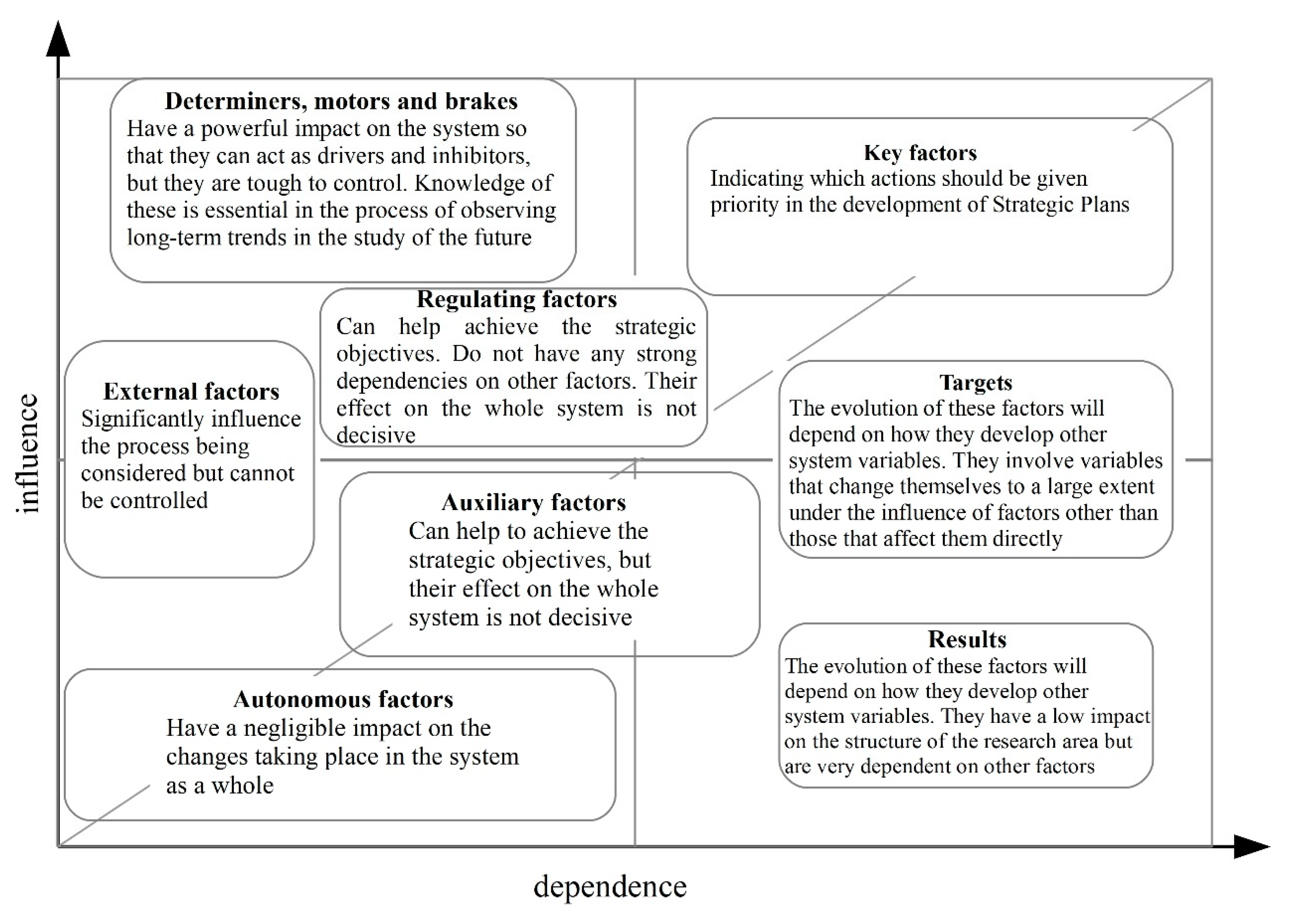
- Key factors—indicating which actions should be given priority in the development of strategic plans,
- Targets—the evolution of these factors will depend on how other system variables evolve. They involve variables that change themselves to a large extent under the influence of factors other than those that affect them directly,
- Results—the evolution of these factors will depend on how other system variables evolve. They have a low impact on the structure of the research area but are very dependent on other factors,
- Determiners, motors and brakes—have a powerful impact on the system so that they can act as drivers and inhibitors, but they are tough to control. Knowledge of these is essential in the process of observing long-term trends in the study of the future,
- Regulating factors—can help achieve the strategic objectives. Do not have any strong dependencies on other factors. Their effect on the whole system is not decisive,
- External factors—significantly influence the process being considered but cannot be controlled,
- Auxiliary factors—can help to achieve the strategic objectives, but their effect on the whole system is not decisive,
- Autonomous factors—have a negligible impact on the changes taking place in the system as a whole.
3. Survey Description
4. Results
- variables 1 → 47, the “Formal constraints related to a local nature protection area” strongly influence the “Local regulations on CO2 storage”, the weight of influence is estimated as 3 (where 0 means no influence and 3 is the strongest influence),
- variables 2 → 3, the “Current primary energy carrier for heat supply” strongly influences the “Quality of air”, the weight of influence is 3,
- variables 39 → 3, the “The degree of urbanisation of the area” strongly influences the “Quality of air”, the weight of influence is 3.
- 21 (“Preferential tax discounts”) → 18 (“Financial support for CO2-EGS systems in an early stage of technological development”), the influence is obvious,
- 20 (“CO2 emission price”) → 18 (“Financial support for CO2-EGS systems in an early stage of technological development”), the price of CO2 emissions might affect the financial support for the CO2-EGS. However, the price of the emissions might support solutions able to reduce it. Variable 20 belongs to the group of “External factors” (Figure 5),
- 47 (“Local regulations on CO2 storage”) ↔ 45 (“Local authority interest”), the influence is quite obvious,
- 45 (“Local authority interest”) → 1 (“Formal constraints related to a local nature protection area”), the influence of “Local authority interest” affects the “Formal constraints”,
- 45 (“Local authority interest”) → 46 (“Local regulations on the utilisation of geothermal energy”), from this result it obviously appears that the local interest influences local regulations,
- 2 (“Current primary energy carrier for heat supply”) → 1 (“Formal constraints related to a local nature protection area”), one can find logical connections between the variables. It is preferable that the areas where the use of fuels that pollute the environment by combustion products is allowed were not nature protection zones. Establishment of a protection zone suggests the use of clean energy sources,
- 47 (“Local regulations on CO2 storage”) ↔ 46 (“Local regulations on geothermal energy utilisation”), the interrelation between variables seems to be reasonable,
- 9 (“Level of Technological Readiness”) → 16 (“Cost of obtaining CO2 at a specific location”), the influence of these variables seems to be illogical.
5. Critical Recommendation for the Selection of Parameters Used for the Location of Potential Zones for CO2-EGS
- “Formal constraints” related to a local nature protection area—this variable seems to be very important in the case of an onshore system. For an offshore system, especially located in the area of natural resources, it probably falls outside of any additional formal constraints,
- “Availability of CO2 sources” (important for both off- and onshore systems),
- “Geological recognition level” (necessary for both systems),
- “The distance of CO2-EGS from a thermal energy user and electricity grid” (important for both).
- “Existing wells and other infrastructure”,
- “Depth of the EGS system”,
- “Water depth” if offshore—its variation is only important in the case of offshore,
- “Physical parameters of reservoir rocks”,
- “Reservoir temperature”.
6. Summary
- Formal constraints related to the local nature protection areas—this variable is essential in the case of an onshore system,
- Availability of CO2 sources,
- Level of geological recognition,
- The distance of the CO2-EGS from a thermal energy user and electricity grid,
- Existing wells and other infrastructure,
- Depth of the EGS system,
- Water depth if offshore, this variable is only important when offshore systems are involved,
- Physical parameters of reservoir rocks,
- Reservoir temperature.
Author Contributions
Funding
Institutional Review Board Statement
Informed Consent Statement
Data Availability Statement
Acknowledgments
Conflicts of Interest
Appendix A

| No | Long Label | Short Label | Description/Explanation | Thematic Scope |
|---|---|---|---|---|
| 1 | Formal constraints related to a local nature protection area | RestrictEnvLoc | E.g., location within or close to protected areas, environmental restrictions | Environment |
| 2 | Current primary energy carrier for heat supply | UsedHeatSource | Primary energy carrier commonly used by surrounding energy users | Environment |
| 3 | Quality of air | AirQuality | Air quality, bad air quality suggests that a great deal may be done to improve it | Environment |
| 4 | Long term safety when exploiting the CO2-EGS system | LongThermSafety | Long term safe exploitation of the CO2 HDR system is important for the environment. This factor is important on a global scale (worldwide) but is crucial on a local scale | Environment |
| 5 | Power and energy demand of direct energy user (DHS) 1 | UserP&Q | Direct user of power and energy that is utilising energy for space heating and hot water preparation | Technical |
| 6 | Supply temperature requirements of direct energy user (DHS) | UserTemp | The requirement with regard to supply temperature is important in the case of direct energy use. The higher the temperature required, the narrower the range of direct use without additional peak heating. A high supply temperature may also cause a high return temperature and reduce the efficiency of the installation | Technical |
| 7 | Availability of CO2 sources | AvailResCO2 | The long-term stability of CO2 supplies should also be considered as important. Availability of captured CO2 at proper purity | Technical |
| 8 | Availability of cooling water (ground, river, lake, sea) | AvailCoolWater | Cold water is an excellent cooling medium for electricity production. If it lies in the ground, this temperature may not be constant over time until it is used | Technical |
| 9 | Level of Technological Readiness | TechReaLev | Level of technological readiness of fracturing, drilling, utilisation of energy carrier. The technology used should be mature | Technical |
| 10 | CO2-EGS system operational parameters | CO2EGSoperPrm | Inlet and outlet pressure of the EGS system, thermosiphon effect, erosion of the CO2 components | Technical |
| 11 | Availability and stability of time-dependent parameters | TimeDesignPrm | E.g., rapid decrease in the available temperature due to excessive exploitation time due to circulation of fluid. Test regime to identify hydraulic and thermal short-circuits, and thus corresponding preventive actions | Technical |
| 12 | Equipment and machinery for supercritical utilisation of CO2 | EandMsCO2 | Availability, performance, costs, maturity, etc. | Technical |
| 13 | Existing wells and other infrastructure | ExistWells | Presence of existing wells into or near a reservoir. Relevant for reusing old oil and gas reservoirs? Could reduce risk of drilling if one could reuse, and increase risk of leaks | Technical |
| 14 | Onshore/offshore | OnOffShore | Offshore sites are probably going to have very different conditions, constraints, and demands | Technical |
| 15 | Water depth if offshore | WaterDepthOff | Water depth over the seabed. Affects thermosiphon, technical installations, heat loss to water, etc. | Technical |
| 16 | Cost of obtaining CO2 at a specific location | CO2Cost | Cost of CO2 at the CO2-EGS location (including capture, transport, purification, etc.) | Economy |
| 17 | Geothermal system risk insurance fund | GeoRiskInsurance | Drilling, operation, monitoring, maintenance, etc. | Economy |
| 18 | Financial support for CO2-EGS systems in an early stage of technological development | FinSuppCO2EGS | Financial support for the preliminary survey and assessment, investment, and operational phase | Economy |
| 19 | Accuracy of CAPEX estimate—especially for drilling and fracturing | AccurInestDrillFrac | Drilling and fracturing are the key points. Most investment expenditure is combined with that element. Even a slight error in the investment estimate strongly influences the economic effects. Both depend on the geological conditions, which are uncertain in 100% of cases | Economy |
| 20 | CO2 emission price | CO2emPrice | EU Emissions Trading System (EU ETS) | Economy |
| 21 | Preferable tax discounts | TaxDisc | As the technology is in its early stage, a lot of factors are currently uncertain. If this technology is going to be developed, it needs support at an early stage. Lump sum tax benefits and other governmental support regimes? E.g., direct part financing | Economy |
| 22 | Cost of drilling and fracturing | DrilingFractCost | Drilling and fracturing are the most capital intensive factors in the CO2-EGS system | Economy |
| 23 | Price of heat and electricity on the energy market | EnergyActualPrice | Price of heat and electricity produced by other energy carriers | Economy |
| 24 | Cost of energy obtained by the CO2-EGS system | CostOfEnCO2EGS | The cost of energy obtained by the CO2-EGS system is one of the most critical factors. One of the goals of this analysis is to detail knowledge on what and how it influences the cost, and to identify risk and cost-reducing factors | Economy |
| 25 | Hydrogeochemical information | HydroGeochem | Physical and chemical composition of reservoir fluid, mineralisation of geothermal water, chemical and mineralogical composition of underground rock formations | Geology |
| 26 | Availability of other underground resources | AvailOtherResour | Limitations due to the exploitation of other natural resources, e.g., geothermal waters, the possible presence of other minerals, the presence of underground water reservoirs of strategic importance | Geology |
| 27 | Geological recognition level | GeolRecog | Geological risk. The certainty of the local geological structure, the quality of its recognition, the vicinity of boreholes, access to geophysical surveys. Availability of geological and geophysical data. Geophysical data (3D Seismic data) | Geology |
| 28 | Physical parameters of reservoir rocks | RocksPhysicPrm | Thermal conductivity coefficient, specific heat. Geomechanical properties of reservoir rocks. Homogeneity/heterogeneity of geological setting. Porosity and permeability of rock in natural reservoir | Geology |
| 29 | Presence and distribution of natural faults and fractures | FractPres&Distr | Information on existing natural fractures of rock (double-porosity model), tectonic stress regime | Geology |
| 30 | Potential for hydraulic stimulation (fracturing) of the geological formation | PotentFract | Hydraulic fracturing technology—predictability of parameters of the fracture zone. Rock stress measurements | Geology |
| 31 | Natural seismicity at the EGS site | Seismicity | The natural seismicity at the EGS site is crucial for the safety of the installation. Appearance of an additional and uncontrolled fracture might make the system open to CO2 migration | Geology |
| 32 | Stratigraphy and lithology, geological structure | Strat&Lithology | Presence of overlying cap rock, stratigraphic trap, suitable geological structure | Geology |
| 33 | Reservoir temperature | TempResources | The reservoir temperature limits the potential ways of obtaining energy from it (direct, indirect use), its power, and the energy production. The higher the temperature, the more comprehensive the opportunity but the more challenging the working conditions in the system from a technical point of view | Geology |
| 34 | Hydrogeological conditions | HydrogolCondition | The hydrogeological connection between the reservoirs and the surrounding environmental components (other reservoirs, atmosphere, etc.). Risk and detection of any hydraulic and thermal short-circuits | Geology |
| 35 | Depth of the EGS system | DepthEGS | Depth at which the geological formation, the use of which is assumed for the EGS system, is located. The depth influences the temperature (increases it) but also increases the investment expenditure | Geology |
| 36 | Thickness and tightness of isolating overburden | CapRock | Type of cap rock, its thickness and tightness. Those parameters are crucial for the safe exploitation of the system | Geology |
| 37 | Thickness of reservoir | ThicknessRes | The thickness of the reservoir limits the volume of the fracture zone. The higher the volume available for fracturing, the higher energy potential of the system and more stable the parameters even when the flow rate of the working (CO2) fluid is high | Geology |
| 38 | The distance of the CO2 EGS from a thermal energy user and electricity grid | DistanceGrid | Distance between the CO2-EGS and the energy grid and consumers. A long-distance generates a higher investment expenditure and causes high thermal energy losses and electricity consumption (pumping), but increases the local safety of the users | Transportation and logistics |
| 39 | The degree of urbanisation of the area | UrbanArea | The degree of urbanisation of the area might influence in a positive way (short distance to the user) and in a negative (high price of land, limitation due to urbanised surroundings) | Transportation and logistics |
| 40 | Access to surface infrastructure | AccessSurfaceInf | Access to roads, a sufficiently large area of land for drilling and construction works | Transportation and logistics |
| 41 | Qualified personnel for the development and operation of CO2-EGS | ManPower | The availability of professional manpower | Social |
| 42 | Social acceptance of CO2-EGS | SocialAcceptEGS | Social acceptance of CO2-EGS is crucial. Inhabitants in the surrounding area should know the advantages and disadvantages of this technology. They should be well informed | Social |
| 43 | Good practice and examples of utilisation of geothermal energy | GoodPractGeoHeat | Local experience of geothermal exploitation. Use of international experts. | Social |
| 44 | Energy security and policy | EnergySecurity | Energy security at a governmental or local level. The recognition of policy and the legal framework for the technological option. Is CO2-EGS a part of the energy policy in the given country? Political stability—predictability of supporting regimes | Legal and policy |
| 45 | Local authority interest | AuthInterest | Interest and support from local authorities, risk aversion | Legal and policy |
| 46 | Local regulations on the utilisation of geothermal energy | LocalRegulatGeo | Local regulations on the utilisation of geothermal energy influence the CO2-EGS system | Legal and policy |
| 47 | Local regulations on CO2 storage | LocalRegCO2stor | Local regulations on CO2 storage (EU or national level) | Legal and policy |
| 48 | Land ownership type (private ownership, local government ownership) | LandProperty | Terrain accessibility for EGS and surface site. Terrain accessibility for CO2 piping infrastructure | Legal and policy |
References
- Reber, T.; Beckers, K.; Tester, J. The transformative potential of geothermal heating in the U.S. energy market: A regional study of New York and Pennsylvania. Energ Policy 2014, 70, 30–44. [Google Scholar] [CrossRef]
- Shyi-Min, L. A global review of enhanced geothermal system (EGS). Renew. Sust. Energy Rev. 2018, 81, 2902–2921. [Google Scholar]
- Bujakowski, W.; Barbacki, A.; Miecznik, M.; Pająk, L.; Skrzypczak, R. A structural-thermal model of the Karkonosze Pluton (Sudetes Mountains, SW Poland) for hot dry rock (HDR) geothermal use. Arch. Min. Sci. 2016, 61, 917–935. [Google Scholar] [CrossRef]
- Sowiżdżał, A. Possibilities of petrogeothermal energy resources utilization in central part of Poland. Appl. Ecol. Environ. Res. 2016, 14, 555–574. [Google Scholar] [CrossRef]
- Sowiżdżał, A.; Kaczmarczyk, M. Analysis of thermal parameters of Triassic, Permian and Carboniferous sedimentary rocks in central Poland. Geol. J. 2016, 51, 65–76. [Google Scholar] [CrossRef]
- Sowiżdżał, A.; Papiernik, B.; Machowski, G.; Hajto, M. Characterization of petrophysical parameters of the Lower Triassic deposits in prospective location for Enhanced Geothermal System (central Poland). Geol. Q. 2013, 57, 729–744. [Google Scholar] [CrossRef][Green Version]
- Wójcicki, A.; Sowiżdżał, A.; Bujakowski, W. Evaluation of Potential, Thermal Balance and Prospective Geological Structures for Needs of Closed Geothermal Systems (Hot Dry Rocks) in Poland; Ministry of the Environment: Warszawa/Kraków, Poland, 2013.
- Singh, M.; Tangirala, S.K.; Chaudhuri, A. Potential of CO2 based geothermal energy extraction from hot sedimentary and dry rock reservoirs, and enabling carbon geo-sequestration. Geomech. Geophys. Geo 2020, 6, 16. [Google Scholar] [CrossRef]
- Tarkowski, R.; Uliasz-Misiak, B. Prospects for the use of carbon dioxide in enhanced geothermal systems in Poland. J. Clean. Prod. 2019, 229, 1189–1197. [Google Scholar] [CrossRef]
- Sowiżdżał, A.; Gładysz, P.; Pająk, L. Sustainable use of petrothermal resources—A review of the geological conditions in Poland. Resources 2021, 10, 8. [Google Scholar] [CrossRef]
- Gładysz, P.; Sowiżdżał, A.; Miecznik, M.; Pająk, L. Carbon dioxide-enhanced geothermal systems for heat and electricity production: Energy and economic analyses for central Poland. Energy Convers. Manag. 2020, 220, 113142. [Google Scholar] [CrossRef]
- Gładysz, P.; Sowiżdżał, A.; Miecznik, M.; Hacaga, M.; Pająk, L. Techno-economic assessment of a combined heat and power plant integrated with carbon dioxide removal technology: A case study for Central Poland. Energies 2020, 13, 2841. [Google Scholar] [CrossRef]
- Tarkowski, R.; Uliasz-Misiak, B.; Tarkowski, P. Storage of hydrogen, natural gas, and carbon dioxide—Geological and legal conditions. Int. J. Hydrog. Energy 2021, 46, 20010–20022. [Google Scholar] [CrossRef]
- Cui, G.; Ren, S.; Dou, B.; Ning, F. Geothermal energy exploitation from depleted high-temperature gas reservoirs by recycling CO2: The superiority and existing problems. Geosci. Front. 2020, in press. [Google Scholar] [CrossRef]
- Avanthi Isaka, B.L.; Ranjith, P.G.; Rathnaweera, T.D.; Wanniarachchi, W.A.M.; Kumari, W.G.P.; Haque, A. Testing the frackability of granite using supercritical carbon dioxide: Insights into geothermal energy systems. J. CO2 Util. 2019, 34, 180–197. [Google Scholar] [CrossRef]
- Cui, G.; Pei, S.; Rui, Z.; Dou, B.; Ning, F.; Wang, J. Whole process analysis of geothermal exploitation and power generation from a depleted high-temperature gas reservoir by recycling CO2. Energy 2021, 217, 119340. [Google Scholar] [CrossRef]
- Tenière-Buchot, P. L’ABC du Pouvoir; Editions d’Organisation: Paris, France, 1988. [Google Scholar]
- Godet, M. Manuel de Prospective Stratégique—Tome 2—3ème Édition—L’Art et la Méthode; Dunod: Malakoff, France, 2007. [Google Scholar]
- MicMac Structural Analysis. Available online: http://en.laprospective.fr/methods-of-prospective/softwares/59-micmac.html (accessed on 16 December 2020).
- Leśniak, A.; Górka, M. Structural Analysis of Factors Influencing the Costs of Facade System Implementation. Appl. Sci. 2020, 10, 6021. [Google Scholar] [CrossRef]
- Villacortaa, P.J.; Masegosaa, A.D.; Castellanos, D.; Lamataa, M.T. A new fuzzy linguistic approach to qualitative Cross Impact Analysis. Appl. Soft Comput. 2014, 24, 19–30. [Google Scholar] [CrossRef]


| No | Long Label | Short Label | Thematic Scope |
|---|---|---|---|
| 1 | Formal constraints related to a local nature protection area | RestrictEnvLoc | Environment |
| 2 | Current primary energy carrier for heat supply | UsedHeatSource | Environment |
| 3 | Quality of air | AirQuality | Environment |
| 4 | Long term safety when exploiting the CO2-EGS system | LongThermSafety | Environment |
| 5 | Power and energy demand of direct energy user (DHS) 1 | UserP&Q | Technical |
| 6 | Supply temperature requirements of direct energy user (DHS) | UserTemp | Technical |
| 7 | Availability of CO2 sources | AvailResCO2 | Technical |
| 8 | Availability of cooling water (ground, river, lake, sea) | AvailCoolWater | Technical |
| 9 | Level of Technological Readiness | TechReaLev | Technical |
| 10 | CO2-EGS system operational parameters | CO2EGSoperPrm | Technical |
| 11 | Availability and stability of time-dependent parameters | TimeDesignPrm | Technical |
| 12 | Equipment and machinery for supercritical utilisation of CO2 | EandMsCO2 | Technical |
| 13 | Existing wells and other infrastructure | ExistWells | Technical |
| 14 | Onshore/offshore | OnOffShore | Technical |
| 15 | Water depth if offshore | WaterDepthOff | Technical |
| 16 | Cost of obtaining CO2 at a specific location | CO2Cost | Economy |
| 17 | Geothermal system risk insurance fund | GeoRiskInsurance | Economy |
| 18 | Financial support for CO2-EGS systems in an early stage of technological development | FinSuppCO2EGS | Economy |
| 19 | Accuracy of CAPEX estimate—especially for drilling and fracturing | AccurInestDrillFrac | Economy |
| 20 | CO2 emission price | CO2emPrice | Economy |
| 21 | Preferable tax discounts | TaxDisc | Economy |
| 22 | Cost of drilling and fracturing | DrilingFractCost | Economy |
| 23 | Price of heat and electricity on the energy market | EnergyActualPrice | Economy |
| 24 | Cost of energy obtained by the CO2-EGS system | CostOfEnCO2EGS | Economy |
| 25 | Hydrogeochemical information | HydroGeochem | Geology |
| 26 | Availability of other underground resources | AvailOtherResour | Geology |
| 27 | Geological recognition level | GeolRecog | Geology |
| 28 | Physical parameters of reservoir rocks | RocksPhysicPrm | Geology |
| 29 | Presence and distribution of natural faults and fractures | FractPres&Distr | Geology |
| 30 | Potential for hydraulic stimulation (fracturing) of the geological formation | PotentFract | Geology |
| 31 | Natural seismicity at the EGS site | Seismicity | Geology |
| 32 | Stratigraphy and lithology, geological structure | Strat&Lithology | Geology |
| 33 | Reservoir temperature | TempResources | Geology |
| 34 | Hydrogeological conditions | HydrogolCondition | Geology |
| 35 | Depth of the EGS system | DepthEGS | Geology |
| 36 | Thickness and tightness of isolating overburden | CapRock | Geology |
| 37 | Thickness of reservoir | ThicknessRes | Geology |
| 38 | The distance of the CO2 EGS from a thermal energy user and electricity grid | DistanceGrid | Transportation and logistics |
| 39 | The degree of urbanisation of the area | UrbanArea | Transportation and logistics |
| 40 | Access to surface infrastructure | AccessSurfaceInf | Transportation and logistics |
| 41 | Qualified personnel for the development and operation of CO2-EGS | ManPower | Social |
| 42 | Social acceptance of CO2-EGS | SocialAcceptEGS | Social |
| 43 | Good practice and examples of utilisation of geothermal energy | GoodPractGeoHeat | Social |
| 44 | Energy security and policy | EnergySecurity | Legal and policy |
| 45 | Local authority interest | AuthInterest | Legal and policy |
| 46 | Local regulations on the utilisation of geothermal energy | LocalRegulatGeo | Legal and policy |
| 47 | Local regulations on CO2 storage | LocalRegCO2stor | Legal and policy |
| 48 | Land ownership type | LandProperty | Legal and policy |
| Variable Number (see Table 1 and Table A1) | Brief Description of the Variable |
|---|---|
| Key factors (indicating which actions should be given priority in the development of Strategic Plans) | |
| 4 | Long term safety when exploiting the CO2-EGS system |
| 9 | Level of Technological Readiness |
| Targets (the evolution of these factors will depend on how they develop other system variables. They involve variables that change themselves to a large extent under the influence of factors other than those that affect them directly) | |
| 45 | Local authority interest |
| Results (the evolution of these factors will depend on how they develop other system variables. They have a low impact on the structure of the research area but are very dependent on other factors) | |
| 22 | Cost of drilling and fracturing |
| 24 | Cost of energy obtained by the CO2-EGS system |
| 42 | Social acceptance of CO2-EGS |
| 46 | Local regulations on the utilisation of geothermal energy |
| 47 | Local regulations on CO2 storage |
| Determiners, motors and brakes (have a powerful impact on the system so that they can act as drivers and inhibitors, but they are tough to control. Knowledge of these is essential in the process of observing long-term trends in the study of the future) | |
| 14 | Onshore/offshore |
| External factors (significantly influence the process being considered but cannot be controlled) | |
| 10 | CO2-EGS system operational parameters |
| 13 | Existing wells and other infrastructure |
| 35 | Depth of the EGS system |
| 5 | Power and energy demand of direct energy user (DHS) |
| 6 | Supply temperature requirements of direct energy user (DHS) |
| 8 | Availability of cooling water (ground, river, lake, sea) |
| 15 | Water depth if offshore |
| 20 | CO2 emission price |
| 26 | Availability of other underground resources |
| 28 | Physical parameters of reservoir rocks |
| 29 | Presence and distribution of natural faults and fractures |
| 31 | Natural seismicity at the EGS site |
| 32 | Stratigraphy and lithology, geological structure |
| 33 | Reservoir temperature |
| 34 | Hydrogeological condition |
| 37 | Thickness of reservoir |
| 39 | The degree of urbanisation of the area |
| 40 | Access to surface infrastructure |
| Auxiliary factors (can help to achieve the strategic objectives, but their effect on the whole system is not decisive) | |
| 1 | Formal constraints related to a local nature protection area |
| 2 | Current primary energy carrier for heat supply |
| 7 | Availability of the CO2 sources |
| 11 | Availability and stability of time-dependent parameters |
| 16 | Cost of obtaining CO2 at a specific location |
| 18 | Financial support for CO2-EGS systems in an early stage of technological development |
| 27 | Geological recognition level |
| 38 | The distance of the CO2-EGS from a thermal energy user and electricity grid |
| 43 | Good practice and examples of utilisation of geothermal energy |
| 44 | Energy security and policy |
| Autonomous factors (have a negligible impact on the changes taking place in the system as a whole) | |
| 3 | Quality of air |
| 12 | Equipment and machinery for supercritical utilisation of CO2 |
| 17 | Geothermal system risk insurance fund |
| 19 | Accuracy of CAPEX estimate—especially for drilling and fracturing |
| 21 | Preferable tax discounts |
| 23 | Price of heat and electricity on the energy market |
| 25 | Hydrogeochemical information |
| 30 | Potential for hydraulic stimulation (fracturing) of the geological formation |
| 36 | Thickness and tightness of isolating overburden |
| 41 | Qualified personnel for the development and operation of CO2-EGS |
| 48 | Land ownership type (private ownership, local government ownership) |
Publisher’s Note: MDPI stays neutral with regard to jurisdictional claims in published maps and institutional affiliations. |
© 2021 by the authors. Licensee MDPI, Basel, Switzerland. This article is an open access article distributed under the terms and conditions of the Creative Commons Attribution (CC BY) license (https://creativecommons.org/licenses/by/4.0/).
Share and Cite
Pająk, L.; Sowiżdżał, A.; Gładysz, P.; Tomaszewska, B.; Miecznik, M.; Andresen, T.; Frengstad, B.S.; Chmielowska, A. Multi-Criteria Studies and Assessment Supporting the Selection of Locations and Technologies Used in CO2-EGS Systems. Energies 2021, 14, 7683. https://doi.org/10.3390/en14227683
Pająk L, Sowiżdżał A, Gładysz P, Tomaszewska B, Miecznik M, Andresen T, Frengstad BS, Chmielowska A. Multi-Criteria Studies and Assessment Supporting the Selection of Locations and Technologies Used in CO2-EGS Systems. Energies. 2021; 14(22):7683. https://doi.org/10.3390/en14227683
Chicago/Turabian StylePająk, Leszek, Anna Sowiżdżał, Paweł Gładysz, Barbara Tomaszewska, Maciej Miecznik, Trond Andresen, Bjørn S. Frengstad, and Anna Chmielowska. 2021. "Multi-Criteria Studies and Assessment Supporting the Selection of Locations and Technologies Used in CO2-EGS Systems" Energies 14, no. 22: 7683. https://doi.org/10.3390/en14227683
APA StylePająk, L., Sowiżdżał, A., Gładysz, P., Tomaszewska, B., Miecznik, M., Andresen, T., Frengstad, B. S., & Chmielowska, A. (2021). Multi-Criteria Studies and Assessment Supporting the Selection of Locations and Technologies Used in CO2-EGS Systems. Energies, 14(22), 7683. https://doi.org/10.3390/en14227683