Abstract
The development of supercapacitors with high volumetric capacitance and high-rate performance has been an important research topic. Activated carbon (AC), which is a widely used material for supercapacitor electrodes, has different surface structures, porosities, and electrochemical properties. However, the low conductivity of the electrode material is a major problem for the efficient use of AC in supercapacitors. To tackle this challenge, we prepared conductive, additive-free electrodes for supercapacitors by a simple one-pot treatment of AC with melamine (nitrogen source), pitch, and sucrose (both carbon source). Nitrogen-doped and carbon-coated AC was successfully generated after high-temperature heat treatment. The AC was doped with approximately 0.5 at.% nitrogen, and coated with carbon leading to a decreased oxygen content. Thin carbon layers (~10 nm) were coated onto the outer surface of the AC, as shown in TEM images. The modification of the AC surface with a sucrose source is favorable, as it increases the electrical conductivity of AC up to 3.0 S cm−1, which is 4.3 times higher than in unmodified AC. The electrochemical performance of the modified AC was evaluated by conducting agent-free electrode. Although the obtained samples had slightly reduced surface areas after the surface modification, they maintained a high specific surface area of 1700 m2 g−1. The supercapacitor delivered a specific capacitance of 70.4 F cc−1 at 1 mA cm−1 and achieved 89.8% capacitance retention even at a high current density of 50 mA cm−2. Furthermore, the supercapacitor delivered a high energy density of 24.5 Wh kg−1 at a power density of 4650 W kg−1. This approach can be extended for a new strategy for conductivity additive-free electrodes in, e.g., supercapacitors, batteries, and fuel cells.
1. Introduction
Supercapacitors are attractive power sources because of their high power density, fast charge–discharge rate, and long cycle life [1]. They store the charge between the electrode and the electrolyte interface layer, which is classified as an electrochemical double-layer capacitor (EDLC). Supercapacitors with quick faradaic reactions are associated with electric double-layer capacitors mainly using activated carbons (ACs) with a high specific surface area and porous structure as electrode materials [2,3]. This enhances the efficient use of the electrode surface applied in commercial capacitor devices. The use of materials for the optimization of high-performance supercapacitors aims to improve the surface area and electrical conductivity while forming an electrical double layer [4]. Efforts are being made to develop new materials and to improve the material surface for supercapacitor electrodes, which should feature a large capacitance, cyclic stability, and low cost [5,6,7]. For this reason, AC is widely used as a supercapacitor electrode. However, its electrical conductivity is low because of the high number of surface defects. Therefore, it can significantly reduce the capacitance without conducting carbon which is to help improve electrode performance.
Although conductive additive agents can improve the electrical conductivity, ionic conductivity of electrolyte, and rate performance of supercapacitors, the conductive effect of the conductive agent is limited by certain factors. The conducting agent itself does not contribute to the capacitance, nonuniformity of the electrode, low density, and blockage of the pores and does also not influence the volumetric performance. Therefore, it is important to develop a conductive additive-free electrode [8,9,10]. The key point is to improve the electrical conductivity. In this respect, surface functionality helps to improve the performance of AC materials. One of the strategies is nitrogen doping, which has a lone pair of electrons, and the p-electrons of the carbon make the neighboring carbons more electronegative [11,12]. Li et al. synthesized a novel nitrogen/oxygen co-doped carbon sponge [12], which reportedly increased the specific capacitance of AC materials. The nitrogen-containing functional groups increrase the capacitance through the Faradaic reaction and improve the wettability of the electrode [2,13,14]. Melamine is often used as a nitrogen doping source that forms upon the heat treatment of graphitic carbon nitride (g-C3N4) at 550 °C in an inert atmosphere. It has a graphitic structure and contains a large amount of nitrogen.
Another strategy is to coat the carbon on the surface of the AC without a conductive additive [9,15]. In general, pitch and sucrose are used as carbon-coating sources. Sucrose is an organic compound that can turn into a carbon material after pyrolysis [16,17,18]. It is mostly used as a carbon coating source in order to form a thin graphitic layer. Qi et al. [16] reported that the sucrose-derived carbons are distributed throughout the AC to form a conductive network [16,19]. Jung et al. [20] found that petroleum pitch has fluid properties near the softening point, which helps to wrap the entire surface of the AC. Pitch dissolved in tetrahydrofuran (THF) has an isotropic pitch containing many aromatic structures [20,21,22,23]; thus, it can be easily oriented to a graphitic structure. Both candidate groups are expected to be suitable as materials for improving the conductivity of AC.
In this study, we report a one-pot process for the preparation of nitrogen-doped and carbon-coated AC with two different carbon coating sources that can be directly used as conductive additive-free electrodes for supercapacitors. The electrode was fabricated without a conducting agent. It featured a good electrical conductivity, large capacitance, and high rate capability. One of the carbon coating sources, sucrose, is the most commonly used carbon coating source owing to its high water solubility and ability to form a thin carbon layer. Another carbon coating source is pitch, which has an isotropic structure to provide aromatic hydrocarbons. A thin carbon layer combined with nitrogen was observed using transmission and scanning electron microscopy (TEM and SEM). We also investigated the structure of the coated carbon and the composition of the nitrogen species. The well-structured porous carbon could be successfully applied as an electrode material for supercapacitors with excellent rate performance [24].
2. Materials and Methods
2.1. Material
The activated carbon, CEP21KS, was commercially available and purchased from Power Carbon Technology Co, Ltd., Jeonju, Korea. Melamine, anhydrous ethanol, 1M Tetraethylammonium tetrafluoroborate in acetonitrile (TEABF4/AN) as electrolyte, and polytetrafluoroethylene (PTFE, 60 wt.% dispersion in H2O) as binder were purchased by Sigma Aldrich, Darmstadt, Germany. All of the chemicals were used as received without further purification.
2.2. Methods
A stoichiometric ratio of 10:5:10 was prepared for CEP21KS as the commercial activated carbon (CAC), melamine as the nitrogen-doping source, and sucrose or pitch as the carbon-coating source. The use of pitch as the carbon source required dissolution in THF and filtering of the solution. Melamine and carbon source were mixed and diluted with deionized water. Then, CAC was added to this solution with continuous stirring, and the final solution was heated to 110 °C in an oil bath to slowly evaporate the water. After complete evaporation, the powder was placed in an alumina crucible and heat-treated at 550 °C for 1 h in an inert atmosphere furnace to form a nitrogen structure from melamine. After that, the temperature was increased again and maintained at 900 °C for 1 h so that the carbon coating layer formed a graphitic structure. AC was coated with nitrogen-doping melamine and carbon in one pot, and the yield was 60%. The sample coated with pitch was denoted as MP, and the sample coated with sucrose was denoted as MS.
2.3. Characterizations
Phase analysis was performed using powder X-ray diffraction (XRD) (Bruker Inc., D8-Advanced, Germany) with Cu Kα radiation (λ = 1.5406 Å). X-ray photoelectron spectroscopy (XPS) was used to investigate the elemental and chemical compositions of the materials using a PHI 5000 Versa Probe (Ulvac-PHI Inc., Japan). The electrical conductivity of samples was measured by Teflon cylinder cell using a current–voltage (I-V) potentiostat (VSP, EC-Lab, Claix, France). The morphologies of the samples were observed using transmission electron microscopy (TEM) (JEOL, JEM-4010, Japan) and scanning electron microscopy (SEM) (JEOL, JSM-7610F, Japan). The pore structures of the samples were characterized by nitrogen adsorption–desorption isotherms at 77 K on a Belsorp-Max surface area analyzer (Belsorp-Max, MicrotracBEL, Japan). The specific surface area and pore volume were calculated using the Brunauer–Emmett–Teller (BET) method and non-local density functional theory (NLDFT). Raman spectra were obtained with a LabRam Aramis (Horiba Jobin Yvon, Japan). The excitation wavelength was 514 nm (Ar ion laser), and the wavenumber was in the range of 500–3000 cm−1.
2.4. Electrochemical Performance
The symmetric supercapacitors were fabricated with rubber-type electrodes and 1 M TEABF4/AN using a 2032-type coin cell. MS, MA, and CAC were used directly as electrode materials for supercapacitors without the addition of conductive additives. The mass ratio of carbon to PTFE binder was 95:5. The mixtures were pressed using a roller press to form 150-µm-thick sheets, which were then dried at 120 °C for 2 h. The electrochemical parameters of the activated carbon electrodes were evaluated using a 2032-type coin cell in a 1.0 M solution of tetraethylammonium tetrafluoroborate (TEABF4) in acetonitrile (AN). Electrochemical tests were performed using a VSP potentiostat (Biologic, France). Electrochemical impedance spectroscopy (EIS) was carried out across the frequency range from 100 mHz to 100 kHz at a signal level of 10 mV. Cyclic voltammetry (CV) curves at various scan rates (1–500 mV s−1) were obtained within a potential range from 0 to 2.7 V. Galvanostatic charge-discharge (GCD) behavior of the supercapacitors were examined in the voltage ranges of 1.0–2.7 V and 0.0–2.7 V at various current densities (1–50 mA cm−2). The volumetric specific capacitance (Cv, F cc−1) and gravimetric specific capacitance (Cg, F g−1) of the supercapacitor were calculated from the GCD curve using Equation (1), and the electrode specific capacitance (Cs, F cc−1) was calculated using Equation (2):
I(A) is the set discharge current, Velectrode is the total volume of the electrode, m is the weight of active materials, dt(s) is the discharge time, and dV(V) is the voltage window upon discharge.
Specific energy (E, Wh kg−1) and power density (P, W kg−1) were obtained using Equations (4) and (5), respectively, using the symmetric cell:
where t (s) is discharge time and dV (V) is the voltage window [25].
3. Results and Discussion
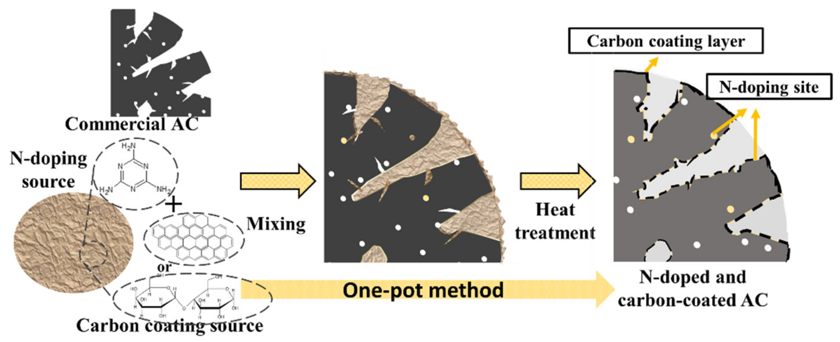
To develop the carbon-coated and nitrogen-doped AC, an interfacial assembly strategy was proposed as illustrated in Scheme 1. As mentioned in the experimental section, the commercial activated carbon (CAC) was fabricated by one-pot method. We used an N-doped source of melamine and two different carbon coating sources, pitch or sucrose, denoted as MP and MS, respectively.

Scheme 1.
Schematic of the electrode preparation.
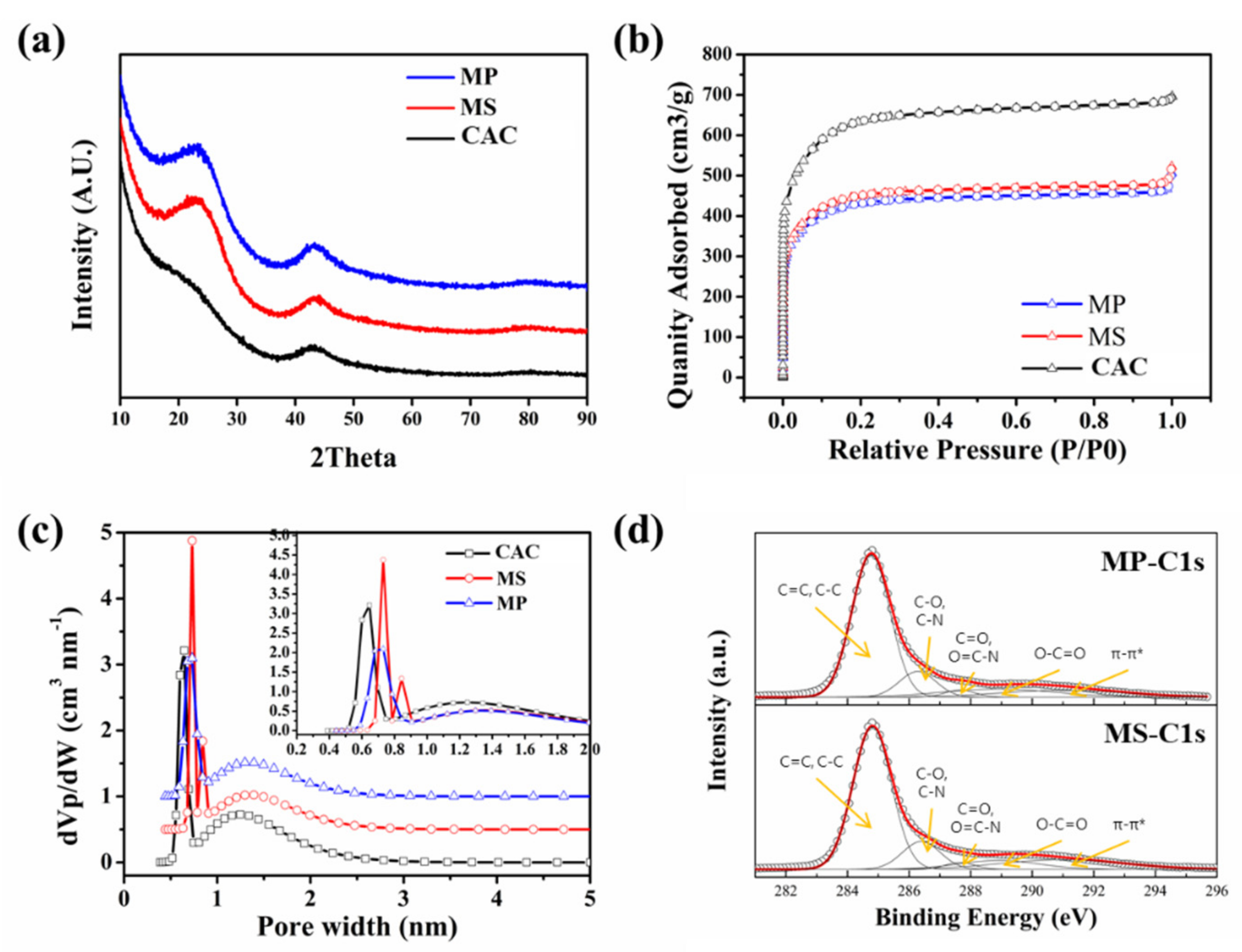
The activated carbon (AC) was fabricated via bath synthesis using melamine as an N-doping source and pitch and sucrose as two different carbon coating sources. The X-ray diffraction (XRD) patterns in Figure 1a confirm the phase composition of the carbon material. CAC, MP, and MS contain two diffraction peaks centered at approximately 22.5° and 43°, which can be assigned to the (002) and (100) planes, respectively. The presence of a wide hump peak around 23° can be explained by the low graphitization of porous carbon compared with that of the graphite (2θ = 25°) diffraction peaks (JCPDS card no. 75-1621) [26,27,28]. The peaks of MP and MS are slightly sharper than the peaks of CAC because of the graphitic carbon coating derived from pitch or sucrose [16].

Figure 1.
(a) XRD pattern; (b) N2 adsorption–desorption isotherm; (c) Pore-size distribution and micropore distribution in the inset graph of CAC, MP, and MS; (d) C 1s XPS spectra of MS and MP.
The Brunauer–Emmett–Teller (BET) method was used to calculate the specific surface area, and the total pore volume was calculated at a relative pressure of 0.990. Figure 1b presents the nitrogen adsorption–desorption isotherms of the samples. These isotherms can be categorized as isotherm I according to the IUPAC classification, indicating that the pores resided in the substantial micropores. A summary of the pore structure analysis is provided in Table 1. The specific surface area (SBET) of CAC was 2060 m2 g−1, which is largely affected by micropores [29]. The samples MS and MP exhibited an SBET of 1700 m2 g−1 and 1620 m2 g−1, with a total pore volume of 0.76 cm3 g−1 and 0.73 cm3 g−1, respectively. The changed pore size distribution using the nonlocal density functional theory (NLDFT) are shown in Figure 1c. All the samples exhibited micropore distribution peaks between 0.4 and 1.0 nm in the inset graph. The peaks of MS and MP are slightly shifted to the higher pore-width side, indicating a reduction in the number of pores not generating capacitance. This suggests that the capacitance is not decreased despite the decrease of the total volume of pores.

Table 1.
Physical and electrical conductivity properties of CAC, MS, and MP.
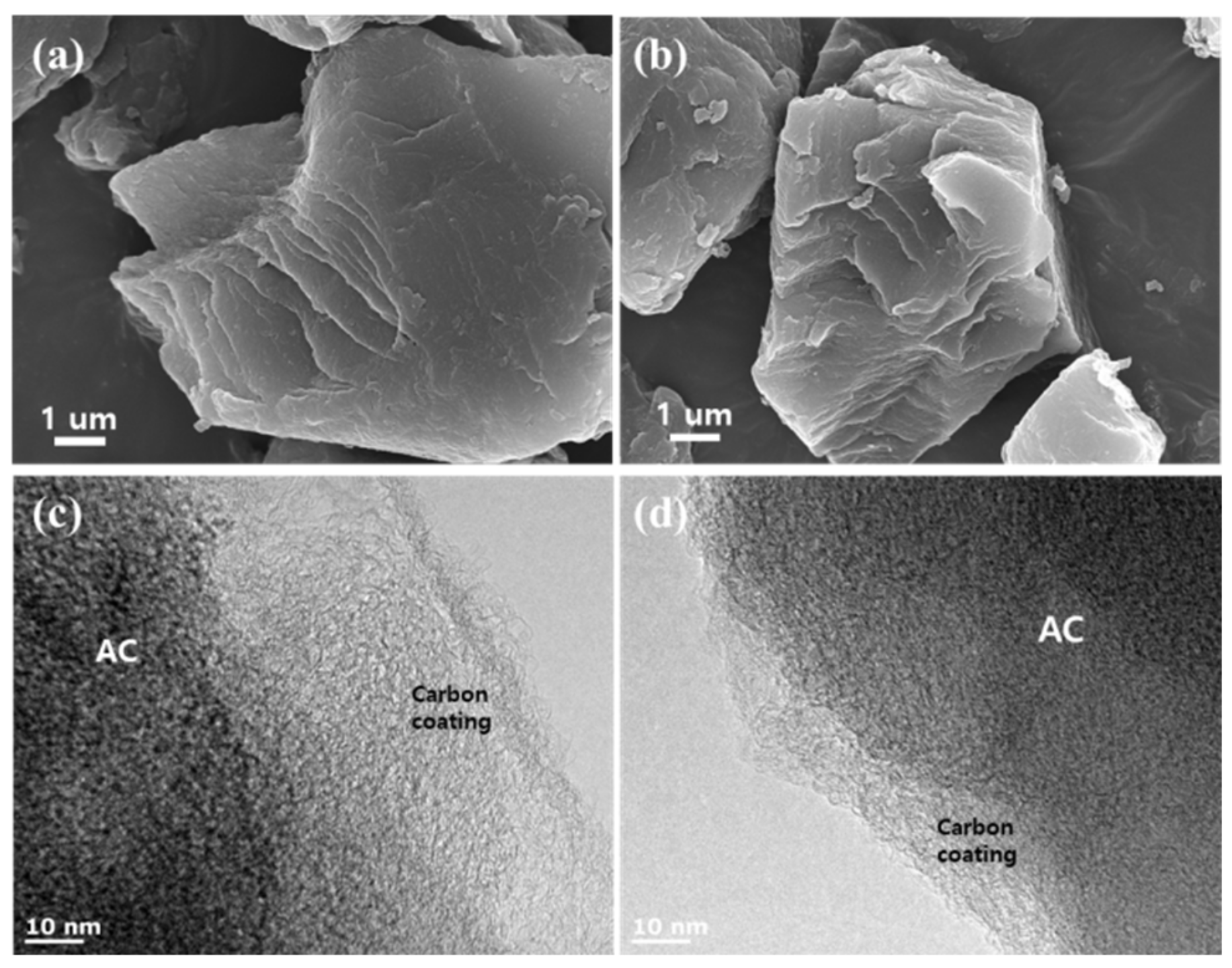
The SBET and pore volume decreased after N-doping and carbon coating because the AC was coated by the sucrose- and pitch-derived carbon, and their porous texture is therefore sacrificed. The surfaces of MS and MP are smoother than the surface of CAC, as can be seen in the SEM images (Figure 2a,b) [26].

Figure 2.
Scanning electron microscopy and high-resolution transmission electron microscopy images of (a,c) MS and (b,d) MP.
The surface atomic composition and functional groups of the samples were further examined by X-ray photoelectron spectroscopy (XPS) on the basis of their binding energies and assignments of C1s, O1s, and N1s as shown in Figure 1d, Figure S2 and Table S1. In Figure S2, the C1s, and a weak peak of O1s and N1s, at approximately 285, 532, and 400 eV, respectively, can also be observed, indicating that the samples mainly contain C, O, and N elements. Table 1 shows the atomic percentages obtained from the XPS analyses. The C-coating and N-doping lead to a decreased O content and increased C and N contents. MS contains 1.0 at.% oxygen and 0.5 at.% nitrogen. The deconvolution of the C1s for CAC was observed in five-carbon states as follows: C=C and C-C at 284.8 eV, C-O at 286.0 eV, C=O at 287.1 eV, O-C=O at 288.7 eV, and π-π* at 290.5 eV [30]. MS and MP showed similar functional groups based on the C1s spectrum fitting (Table S2).
As shown in Figure S3, two broad peaks at approximately 1350 cm−1 and 1580 cm−1 represent the D and G band, respectively, for all products. The D band corresponds to defects and impurities, while the G band corresponds to the graphitic structure. The ID/IG ratio of MS (0.92) and MP (0.88) is higher than that of CAC (0.86) because nitrogen doping decreases the long-range crystalline order by introducing nitrogen atoms onto the carbon lattice [17,31]. This lower crystallinity then leads to a lower Id/Ig ratio. Moreover, the broad region at 1500 cm−1 is assigned to amorphous carbon, which showed a lower intensity after surface modification [32,33]. The lower intensity of MS compared with that of other samples indicates the conversion of the carbon source into nanocrystalline graphitic domains during heat treatment [19]. Thus, the Raman spectra agree well with the electrical conductivity results. The electrical conductivities of each carbon are summarized in Table 1. The electrical conductivities of MS (3.0 S cm−1) and MP (2.1 S cm−1) are improved, compared with that of CAC. In both samples, the oxygen content decreased, and the electrical conductivity increased upon N-doping. According to the XPS spectra, the best result of MS could be attributed to the doping effect of the electron-rich nitrogen in the carbon layer (C-N) and π-π* graphitic structure [14,28,34]. The pitch-derived THF has an isotropic structure and the characteristic that its graphitization is not as good as that of an anistropic structure [35,36].
The conductivity of the electrode material was directly related to the rate performance of the supercapacitor. The degree of graphitization was further investigated using TEM, as shown in Figure 2. All images are consistent with the graphitic structure of the carbon-coated layer [17]. The sucrose-derived carbon is distributed on the surface of the AC to form conductive interconnected particles [19]. This improves the electrical conductivity during the electrochemical charging and discharging processes, even with conductive, additive-free electrodes.
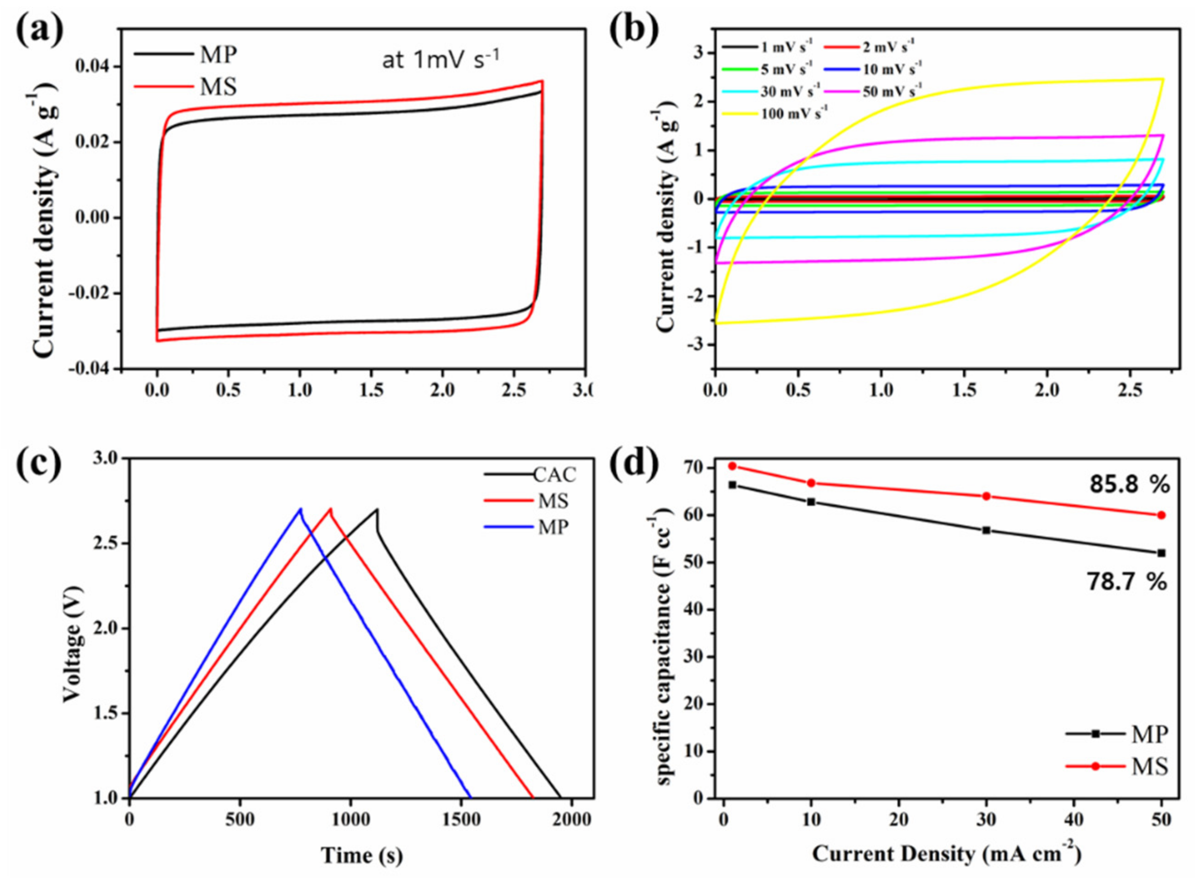
Electrochemical measurements were performed to evaluate the supercapacitor performance with conductive additive-free electrodes. The capacitive behavior was subsequently demonstrated by CV in a 1 M TEABF4/AN electrolyte and a voltage window of 0–2.7 V. The comparative CV plots of these samples were obtained at various dosages at a scan rate of 1 mV s−1, as shown in Figure 3a. All the CV curves exhibit an approximately rectangular shape, which is an ideal capacitive behavior. We observed that the encircled area of MS in the CV curve was larger than that of MP, indicating that MS possesses a higher specific capacitance. The CVs of MS, MP, and CAC were performed with various scan rates of 1–500 mV s−1 shown in Figure 3b, Figures S4 and S5, respectively. With an increase in the CV scan rate, MS and MP gradually lost their rectangular shape and capacitance but almost retained their rectangular shape even at a high potential scan rate of 500 mV s−1. However, CAC began to show a distorted shape from 30 mV s−1. This is because there are no additive conductivity agents to move electrons in the electrode of the supercapacitor. While the electrodes of MS and MP also do not have additive conductive agents, the CV curves almost retain their rectangular shapes with only little distortion. This is because the coated carbon and the electron-rich carbon shortened the electron transport distance [14]. This result might be attributed to the N-doping, which improved the hydrophilicity.

Figure 3.
(a) Cyclic voltammetry curves of MP and MS at 1 mV s−1 in a symmetric two electrode supercapacitor; (b) Cyclic voltammetry curves of MS measured with different scan rate; (c) GCD profile of MS, MP, and CAC at 1 mA cm−2; (d) The specific capacitance calculated based on galvanostatic charging–discharging at different current densities.
Figure 3c and Figure S6 display the symmetric GCD profile with a negligible IR drop at the beginning of the discharge process. As shown in the GCD curves of the samples at different current densities ranging from 1 mA cm−2 to 50 mA cm−2, the MS and MP curves are almost symmetrical with a small IR drop. The volumetric capacitance of MS at a low current density of 1 mA cm−2 is 70.4 F cc−1, and even at a high current density of 50 mA cm−2, the MS still provides a volumetric capacitance of 60 F cc−1 owing to the increased wettability of the pore walls which is attributed to the N-functional group derived from sucrose [25]. However, because the surface area porosity of activated carbon plays a key role in determining the performance of the supercapacitor, CAC exhibits a higher volumetric capacitance of 70.8 F cc−1 at 1 mA cm−2, although it is difficult to calculate because of the 2.1 V IR drop at a high current density of 50 mA cm−2. The volumetric capacitance of CAC amounts to 6.9 F cc−1 at 50 mA cm−2 and was calculated using the discharge profile, thereby excluding the IR drop. After nitrogen-doping and carbon-coating, the specific surface areas of MS and MP reduced. However, the amount of micropores that did not develop capacity also reduced; hence, there was no significant difference in the capacitances of the raw materials. Figure S8 shows the cycling stability of the MS supercapacitor, which maintained 89.8 % of its initial capacitance after 10,000 cycles at a current density of 10 mA cm−2, indicating a superior long cycling life. Figure S7 further shows a comparison between compares the electrochemical impedance spectra of the samples in the organic electrolyte. Compared with MS and MP, it exhibits relatively lower intrinsic ohmic resistances and equivalent series resistances in the high-frequency region and a higher slope in the low-frequency region, demonstrating lower contact resistance, better electrolyte accessibility, and good ion/electron transportation [25]. Figure S9 shows the Ragone plots of MS, MP, and CAC. The energy density and power density were calculated based on the total mass of both electrodes. MS exhibited the high energy density of 24.5 Wh kg−1 with a power density of 4260 W kg−1, which is higher than a specific energy for MP and CAC. The detailed comparison is listed in Table S2. In terms of energy and power density, the N-doped and C-coated ativated carbon synthesized in this study was superior to those proposed in previously reported studies.
4. Conclusions
In summary, we designed and developed a facile one-pot method for constructing carbon-coated and nitrogen-doped activated carbon (AC). Two different carbon sources were studied in detail to confirm an optimal structure. The MS and MP samples retained a reduced oxygen percentage of 0.5 at.% and an increased nitrogen percentage of 1.0 at.%. MS has a high electrical conductivity of 3.0 S cm−1 featuring a graphitic structure. We found that nitrogen functional groups play a crucial role for further improving the performance. MS exhibited an improved volumetric capacitance of 70.4 F cc−1, as well as a rate retention of 87% at a current density of 50 mA cm−2. We also found that an ideal capacitive behavior was retained even at high scan rates. Furthermore, the samples showed a good cycling stability of 98% after 5000 charge–discharge cycles. These results demonstrate that AC with graphitic carbon and nitrogen can provide guidance for further studies on the preparation of conductive, additive-free electrodes for supercapacitors.
Supplementary Materials
The following are available online at https://www.mdpi.com/article/10.3390/en14227629/s1, Figure S1: SEM images of CAC, Figure S2: XPS survey spectra of samples, Figure S3: Raman spectra of all samples, Figure S4: Cyclic voltammetry curves of MP measured with different scan rate, Figure S5. Cyclic voltammetry curves of CAC measured with different scan rate, Figure S6: GCD profile of (a) CAC, and (b) MP, Figure S7: Comparison of electrochemical imdedance spectroscopy(EIS) of MS and MP, Figure S8: Cycle stability for MP and MS at 10 mA cm−2, Figure S9: Ragone plots, Table S1: Surface elemental composition and C1s bonding composition of of CAC, MS, and MP, Table S2: Comparison of nitrogen-doped activated carbon in TEABF4/AN electrolyte.
Author Contributions
Conceptualization, and methodology, S.-J.J. and K.C.R.; writing—original draft preparation, S.-J.J.; writing—review and editing, K.C.R.; material characterization, S.-J.J., Y.C.K. and S.H.K.; formal analysis, electrochemical tests, and analysis, J.H.L., S.H.K. All authors have read and agreed to the published version of the manuscript.
Funding
This research received no external funding.
Institutional Review Board Statement
Not applicable.
Informed Consent Statement
Not applicable.
Data Availability Statement
Not applicable.
Acknowledgments
This work was supported by the Technology Innovation Program (20004958, Development of ultra-high-performance supercapacitor and high-power module) funded by the Ministry of Trade, Industry & Energy (MOTIE, Korea). This work was supported by the Industrial Strategic Technology Development Program (20012763, development of petroleum residue-x-based porous adsorbent for industrial wastewater treatment) funded by the Ministry of Trade, Industry and Energy (MOTIE, Korea).
Conflicts of Interest
The authors declare no conflict of interest.
References
- Wang, Y.; Zhang, L.; Hou, H.; Xu, W.; Duan, G.; He, S.; Liu, K.; Jiang, S. Recent progress in carbon-based materials for supercapacitor electrodes: A review. J. Mater. Sci. 2021, 56, 173–200. [Google Scholar] [CrossRef]
- Conway, B.E. Electrochemical Supercapacitors: Scientific Fundamentals and Technological Applications; Springer Science & Business Media: New York, NY, USA, 2013. [Google Scholar]
- Navarro, G.; Torres, J.; Blanco, M.; Nájera, J.; Santos-Herran, M.; Lafoz, M. Present and future of supercapacitor technology applied to powertrains, renewable generation and grid connection applications. Energies 2021, 14, 3060. [Google Scholar] [CrossRef]
- Chae, J.S.; Kang, W.-S.; Roh, K.C. sp2–sp3 hybrid porous carbon materials applied for supercapacitors. Energies 2021, 14, 5990. [Google Scholar] [CrossRef]
- Wang, Q.; Yan, J.; Fan, Z. Carbon materials for high volumetric performance supercapacitors: Design, progress, challenges and opportunities. Energy Environ. Sci. 2016, 9, 729–762. [Google Scholar] [CrossRef]
- Raymundo-Piñero, E.; Cadek, M.; Béguin, F. Tuning carbon materials for supercapacitors by direct pyrolysis of seaweeds. Adv. Funct. Mater. 2009, 19, 1032–1039. [Google Scholar] [CrossRef]
- Jang, S.-J.; Kang, Y.C.; Roh, K.C. Preparation of activated carbon decorated with carbon dots and its electrochemical performance. J. Ind. Eng. Chem. 2020, 82, 383–389. [Google Scholar] [CrossRef]
- Na, R.; Lu, N.; Li, L.; Liu, Y.; Luan, J.; Wang, G. A robust conductive polymer network as a multi-functional binder and conductive additive for supercapacitors. Chem. Electro. Chem. 2020, 7, 3056–3064. [Google Scholar] [CrossRef]
- Lee, S.-H.; Kim, K.-Y.; Yoon, J.-R. Binder-and conductive additive-free laser-induced graphene/LiNi 1/3 Mn 1/3 Co 1/3 O 2 for advanced hybrid supercapacitors. NPG Asia Mater. 2020, 12, 28. [Google Scholar] [CrossRef]
- Cheng, Q.; Tang, J.; Ma, J.; Zhang, H.; Shinya, N.; Qin, L.-C. Graphene and nanostructured MnO2 composite electrodes for supercapacitors. Carbon 2011, 49, 2917–2925. [Google Scholar] [CrossRef]
- Mirzaeian, M.; Abbas, Q.; Hunt, M.; Hall, P. Pseudocapacitive effect of carbons doped with different functional groups as electrode materials for electrochemical capacitors. Energies 2020, 13, 5577. [Google Scholar] [CrossRef]
- Zhang, R.; Jing, X.; Chu, Y.; Wang, L.; Kang, W.; Wei, D.; Li, H.; Xiong, S. Nitrogen/oxygen co-doped monolithic carbon electrodes derived from melamine foam for high-performance supercapacitors. J. Mater. Chem. A 2018, 6, 17730–17739. [Google Scholar] [CrossRef]
- Le Comte, A.; Pognon, G.; Brousse, T.; Belanger, D. Determination of the quinone-loading of a modified carbon powder-based electrode for electrochemical capacitor. Electrochemistry 2013, 81, 863–866. [Google Scholar] [CrossRef] [Green Version]
- Jeong, H.M.; Lee, J.W.; Shin, W.H.; Choi, Y.J.; Shin, H.J.; Kang, J.K.; Choi, J.W. Nitrogen-doped graphene for high-performance ultracapacitors and the importance of nitrogen-doped sites at basal planes. Nano Lett. 2011, 11, 2472–2477. [Google Scholar] [CrossRef]
- Yoon, S.; Kim, H.; Oh, S.M. Surface modification of graphite by coke coating for reduction of initial irreversible capacity in lithium secondary batteries. J. Power Sources 2001, 94, 68–73. [Google Scholar] [CrossRef]
- Qi, Y.; Zhang, M.; Qi, L.; Qi, Y. Mechanism for the formation and growth of carbonaceous spheres from sucrose by hydrothermal carbonization. RSC Adv. 2016, 6, 20814–20823. [Google Scholar] [CrossRef]
- Li, Z.; Xu, Z.; Wang, H.; Ding, J.; Zahiri, B.; Holt, C.M.; Tan, X.; Mitlin, D. Colossal pseudocapacitance in a high functionality–high surface area carbon anode doubles the energy of an asymmetric supercapacitor. Energy Environ. Sci. 2014, 7, 1708–1718. [Google Scholar] [CrossRef]
- Jang, M.; Ko, D.; Choi, Y.; Yan, B.; Jin, X.; Kim, D.K.; Piao, Y. Self-organized hierarchically porous carbon coated on carbon cloth for high-performance freestanding supercapacitor electrodes. J. Electroanal. Chem. 2021, 895, 115456. [Google Scholar] [CrossRef]
- Kim, S.-K.; Park, H.S. Multiwalled carbon nanotubes coated with a thin carbon layer for use as composite electrodes in supercapacitors. RSC Adv. 2014, 4, 47827–47832. [Google Scholar] [CrossRef]
- Jung, D.E.; Chung, D.; Yoon, S.-H.; Kim, B.C. The preparation and properties of isotropic pitch-based carbon felt prepared by solvent-supported dual concentric electrospinning. Macromol. Res. 2019, 27, 1024–1029. [Google Scholar] [CrossRef]
- Kim, B.-J.; Kil, H.; Watanabe, N.; Seo, M.-H.; Kim, B.-H.; Yang, K.S.; Kato, O.; Miyawaki, J.; Mochida, I.; Yoon, S.-H. Preparation of novel isotropic pitch with high softening point and solvent solubility for pitch-based electrospun carbon nanofiber. Curr. Org. Chem. 2013, 17, 1463–1468. [Google Scholar] [CrossRef]
- Kim, B.-J.; Kotegawa, T.; Eom, Y.; An, J.; Hong, I.-P.; Kato, O.; Nakabayashi, K.; Miyawaki, J.; Kim, B.C.; Mochida, I. Enhancing the tensile strength of isotropic pitch-based carbon fibers by improving the stabilization and carbonization properties of precursor pitch. Carbon 2016, 99, 649–657. [Google Scholar] [CrossRef]
- Kim, B.-J.; Eom, Y.; Kato, O.; Miyawaki, J.; Kim, B.C.; Mochida, I.; Yoon, S.-H. Preparation of carbon fibers with excellent mechanical properties from isotropic pitches. Carbon 2014, 77, 747–755. [Google Scholar] [CrossRef]
- Lee, K.-C.; Lim, M.S.W.; Hong, Z.-Y.; Chong, S.; Tiong, T.J.; Pan, G.-T.; Huang, C.-M. Coconut shell-derived activated carbon for high-performance solid-state supercapacitors. Energies 2021, 14, 4546. [Google Scholar] [CrossRef]
- Mitravinda, T.; Anandan, S.; Sharma, C.S.; Rao, T.N. Design and development of honeycomb structured nitrogen-rich cork derived nanoporous activated carbon for high-performance supercapacitors. J. Energy Storage 2021, 34, 102017. [Google Scholar] [CrossRef]
- Qiu, X.; Wang, L.; Zhu, H.; Guan, Y.; Zhang, Q. Lightweight and efficient microwave absorbing materials based on walnut shell-derived nano-porous carbon. Nanoscale 2017, 9, 7408–7418. [Google Scholar] [CrossRef]
- Li, Z.; Lu, C.; Xia, Z.; Zhou, Y.; Luo, Z. X-ray diffraction patterns of graphite and turbostratic carbon. Carbon 2007, 45, 1686–1695. [Google Scholar] [CrossRef]
- Altinci, O.C.; Demir, M. Beyond conventional activating methods, a green approach for the synthesis of biocarbon and its supercapacitor electrode performance. Energy Fuels 2020, 34, 7658–7665. [Google Scholar] [CrossRef]
- Cheng, F.; Yang, X.; Zhang, S.; Lu, W. Boosting the supercapacitor performances of activated carbon with carbon nanomaterials. J. Power Sources 2020, 450, 227678. [Google Scholar] [CrossRef]
- Gengenbach, T.R.; Major, G.H.; Linford, M.R.; Easton, C.D. Practical guides for x-ray photoelectron spectroscopy (XPS): Interpreting the carbon 1s spectrum. J. Vac. Sci. Technol. A Vac. Surf. Film. 2021, 39, 013204. [Google Scholar] [CrossRef]
- Dettlaff, A.; Sawczak, M.; Klugmann-Radziemska, E.; Czylkowski, D.; Miotk, R.; Wilamowska-Zawłocka, M. High-performance method of carbon nanotubes modification by microwave plasma for thin composite films preparation. RSC Adv. 2017, 7, 31940–31949. [Google Scholar] [CrossRef] [Green Version]
- Sadezky, A.; Muckenhuber, H.; Grothe, H.; Niessner, R.; Pöschl, U. Raman microspectroscopy of soot and related carbonaceous materials: Spectral analysis and structural information. Carbon 2005, 43, 1731–1742. [Google Scholar] [CrossRef]
- Dychalska, A.; Popielarski, P.; Franków, W.; Fabisiak, K.; Paprocki, K.; Szybowicz, M. Study of CVD diamond layers with amorphous carbon admixture by Raman scattering spectroscopy. Mater. Sci.-Pol. 2015, 33, 799–805. [Google Scholar] [CrossRef] [Green Version]
- Skorupska, M.; Kamedulski, P.; Lukaszewicz, J.P.; Ilnicka, A. The improvement of energy storage performance by sucrose-derived carbon foams via incorporating nitrogen atoms. Nanomaterials 2021, 11, 760. [Google Scholar] [CrossRef] [PubMed]
- Castro, L.D.d. Anisotropy and mesophase formation towards carbon fibre production from coal tar and petroleum pitches: A review. J. Braz. Chem. Soc. 2006, 17, 1096–1108. [Google Scholar] [CrossRef]
- Yuan, G.; Xue, Z.; Cui, Z.; Westwood, A.; Dong, Z.; Cong, Y.; Zhang, J.; Zhu, H.; Li, X. Constructing the bridge from isotropic to anisotropic pitches for preparing pitch-based carbon fibers with tunable structures and properties. ACS Omega 2020, 5, 21948–21960. [Google Scholar] [CrossRef]
Publisher’s Note: MDPI stays neutral with regard to jurisdictional claims in published maps and institutional affiliations. |
© 2021 by the authors. Licensee MDPI, Basel, Switzerland. This article is an open access article distributed under the terms and conditions of the Creative Commons Attribution (CC BY) license (https://creativecommons.org/licenses/by/4.0/).