Abstract
The process of cutting rocks with a boom-type roadheader results in extreme dynamic loads and vibrations. Mining, especially in the case of hard rocks, is associated with large energy consumption, which, when combined with low process efficiency, can lead to low drilling performance. These phenomena are undesirable because excessive dynamic load leads to low machine durability, as well as deterioration of work conditions and safety. Low mining efficiency affects the economics of mining works conducted using roadheaders. However, these adverse effects can be minimized by optimizing the cutting process, thanks to the automatic control of the roadheader. The present article discusses the concept of automatic control of a boom-type roadheader’s cutting heads movement. Based on previously conducted computer investigations, it was assumed that reducing the energy consumption of the cutting process and improving the dynamic state of the roadheader (objective functions) are possible only by controlling three of the four parameters characterizing the cutting process: angular speed of the cutting heads, boom swinging speed, and cut height. The web of cut and workability of the rock can be treated as variables of a stochastic nature. This paper presents selected results of computer tests during simulated cutting of rocks with different uniaxial compressive strengths (UCS) in automatic and manual mode. In addition, the tests studied the behavior of the roadheader during the cutting of rocks with variable workability, which is typical of drilling excavations in a layered rock mass. The results of simulated cutting in automatic and manual mode were compared to assess the effectiveness of the adopted automatic control strategy. It was found that the algorithm developed for automatic control of the cutting heads’ movement allows reducing the consumption of cutting energy by up to half compared to the consumption during cutting in manual mode. Furthermore, it was found to improve the dynamic state of the machine.
1. Introduction
A prerequisite for the robotization of roadheaders is the automation of cutting, which is their primary working process. This is challenging to achieve due to the non-stationary nature of the cutting process and the operating conditions of the roadheaders. The expected difficulties are mainly caused by the stochastic variability of the environmental conditions in which the drilling process is carried out, and, in particular, the time variability of the mechanical properties of the excavated rocks. In most cases, roadways, tunnels, and other underground engineering structures are drilled in a rock mass consisting of many rock layers often characterized by very different workability (easily workable rocks separated by hard-to-cut rocks). The methods used for retaining these layers are also varied and variable, depending on the course of the rock-forming processes, tectonics, and the spatial orientation of the drilled roadway or tunnel to the rock layers. Boom-type roadheaders are self-propelled, thanks to which they can independently move along the floor of a roadway or tunnel. Their high maneuverability allows drilling excavations of any course, junction, or excavations and tunnels of any shape and size of the cross-section (especially with a width higher than that resulting from the range of the roadheader from one position). The heading face of the roadway is gradually mined using small-sized cutting heads, which significantly distinguish this type of roadheaders from TBMs (tunnel boring machines). However, the undoubted advantages of boom-type roadheaders make the control of cutting process parameters very challenging, especially the web of cut (sumping of the cutting head into the face) and cut height. Control of these parameters requires the determination of the spatial position of the roadheader to the longitudinal axis and the heading face of the excavation.
Automation of the mining process with a boom-type roadheader requires proper planning of the trajectory of the cutting heads on the heading face surface of the drilled excavation, as well as optimization of the cutting process parameters. This optimization must be carried out in real-time (online) using an automatic control system, by adjusting the current values of the cutting process parameters to the current dynamic state of the roadheader, resulting from the rock cutting process. In the commonly used heading face cutting technology with transverse cutting heads, the cutting heads are moved parallel to the floor after sumping, which is a fundamental work movement. The cutting heads are moved up or down after reaching the sidewall of the drilled excavation. Then, the working movement is repeated, but toward the opposite direction [1,2,3]. In the case of a roadheader equipped with a longitudinal cutting head, following the abovementioned cutting technology, another one is applied. In this, after sumping of the cutting heads, the gap formed in the axis of the excavation is spirally expanded until it reaches the intended shape and size of the drilled excavation [4,5]. Such technology is derived from the design of the cutting system of the boom-type roadheaders. One (longitudinal) or two (transverse) cutting heads are located at the end of the movable boom. The boom can be deflecting in a plane either parallel or perpendicular to the floor using hydraulic drives (boom swinging or boom lifting mechanism, respectively) [6].
To achieve robotic drilling of roadways and tunnels with boom-type roadheaders, many issues should be solved. These solutions, together with the automation of the cutting process, can enable making roadheaders a fully autonomous machine. As already mentioned, roadheaders are self-propelled machines equipped with a crawler chassis. Hence, monitoring their spatial position in the excavation is a significant problem, as the required direction of drilling and the shape and size of the cross-section of the excavation should be ensured. Due to the automatic control of the cutting heads’ movement, there is also a need to monitor their trajectories [7,8,9,10]. One method to solve this problem is to use vision systems that can remotely track the current position of the roadheader and move the cutting heads against the background of the cross-section of the drilled excavation [11]. Furthermore, the vision systems allow analyzing the rock structure on the heading face of the roadway, and can therefore be applied, for example, in the selective mining of rocks of different hardness in automatic mode [12,13,14]. Among the tasks that should be solved for automation of the cutting process is the planning of the optimal trajectory of the cutting heads [15,16,17].
Works on the development of an effective automatic control system for controlling the cutting heads movement of the boom-type roadheaders during mining have been carried out in various scientific and research centers in recent years, especially in Poland and China. Several strategies of automatic control were proposed, which assumes a program change of the values of selected cutting process parameters. This usually applies to the swinging speed of the boom in working motion [18,19] or the angular speed of the cutting heads (e.g., using a hydraulic gear [20] or a frequency converter [21,22]). Thus far, such control has been attempted widely using the PID controller. The motor current in the cutting heads drive, its power or torque, the load on the boom deflection actuators, and the acceleration of vibrations were assigned as adjustable quantities. The set value of the controlled parameter was developed using various methods: fuzzy logic, neural networks, or genetic algorithms [23,24,25].
This article presents selected results of computer tests conducted on the operation of the R-130 roadheader (manufactured by Famur SA) equipped with an automatic control system with the proposed structure and operation algorithm. Simulation of rock with different uniaxial compressive strengths (UCS) and cutting performances with variable workability (ascending and descending) were analyzed. The results of the computer simulation of mining in automatic and manual mode were compared for the same external conditions, to determine the effectiveness of the developed control strategy. The essence of the proposed strategy is to control three of the four cutting process parameters: angular velocity of the cutting heads, boom swinging speed, and height of the cut performed during the movement of the cutting heads parallel to the floor (in working motion).
2. Characteristics of the Test Object and the Proposed Idea of Automatic Control of a Roadheader’s Cutting Heads Movement
The object of the computer tests and experimental research was the R-130 boom-type roadheader (Figure 1a). It is the most popular type of roadheader currently used widely to drill roadways in the hard coal mines in Poland. This 32 t machine is equipped with transverse cutting heads which are driven by a 132 kW electric motor [26]. An R-130 boom-type roadheader can drill from one position a roadway with maximum dimensions of 5100 × 4250 mm (width × height) and a maximum cross-sectional area of 22 m2 in rocks with a uniaxial compressive strength of up to 80 MPa [27]. For experimental research, including the analysis carried out for confirming the effectiveness of the automatic control system solution developed for controlling the movement of cutting heads, a natural-scale test stand was built in the Technology Hall of the Department of Mining Mechanization and Robotization (Faculty of Mining, Safety Engineering, and Industrial Automation Control) at the Silesian University of Technology (Poland). The R-130 roadheader was equipped with transverse cutting heads having a diameter (Dmax) of 800 mm and a length (L)—measured along with the pick tips envelope—of 495 mm. Each cutting head was armed with 54 conical picks (U47HD/65YD, manufactured by Kennametal). The motor in the cutting heads drive was powered by the frequency converter, which allowed the smooth change of the angular speed of the cutting heads () from around zero to 9.24 rad/s (for supply voltage frequency f = 50 Hz). In addition, the roadheader was equipped with electrohydraulic valves, which allowed for remote control of the operation of the boom-swinging actuator and boom-lifting actuators (rotation in a plane parallel and perpendicular to the floor, respectively). In the first stage of the bench tests, the movement of the cutting heads was controlled manually from the control panel and later from the controller software (written in LabView) in the automatic control system. The machine was equipped with over 70 sensors to measure its basic parameters, vibrations in its key construction nodes, and dynamic loads, including three picks mounted on the cutting head, the motor in the cutting heads drive, and actuators of the boom deflection mechanisms. All these measurements were taken during the cutting of a cement-sand block made of five transversely inclined layers of varying uniaxial compressive strengths (~30 to ~70 MPa). The geometry and mechanical properties of the block reflected the typical conditions in the heading face of roadways in the underground coal mines of Poland. The course of the cutting process in working motion was investigated, because it is a commonly used technology for cutting the heading face of the roadways and tunnels with boom-type roadheaders equipped with transverse cutting heads, and is especially significant when swinging the boom parallel to the floor. During this movement, the cutting heads perform lower cuts (Figure 1b,d) or upper cuts (Figure 1c,e). Lower cuts are made after the boom is lowered, whereas the upper ones are made after the boom is raised. The size and shape of the cross-section of the cuts made in this way are determined by the web of cut (sumping) z, for which the cutting heads are cut, and the cut height h, which is based on the change made in the boom deflection angle ΔαV (Figure 1d,e). Generally, rock mining occurs when the boom is swinging in a plane parallel to the floor (its rotation around the turntable axis of rotation), and, hence, the surface of the heading face is not flat but has a spherical shape. As a result, the web of cut z is not a fixed value but varies depending on the current boom deflection angles in a plane parallel (αH) and perpendicular (αV) to the floor and the maximum web of cut value: z = f(zmax, αH, αV) (assuming parallelity of the forehead and previous mining cycle). Thus, the cutting geometry is one of the factors that influence the dynamic variability of the roadheader cutting load over time. The web of cut and cut height, together with the angular velocity of the cutting heads (resulting from the set rotational speed of the motor rotor n) and their movement speed in the working motion (boom swinging velocity in a plane parallel to the floor) vOW, constitute a set of parameters that characterize the process of rock cutting with a boom-type roadheader.
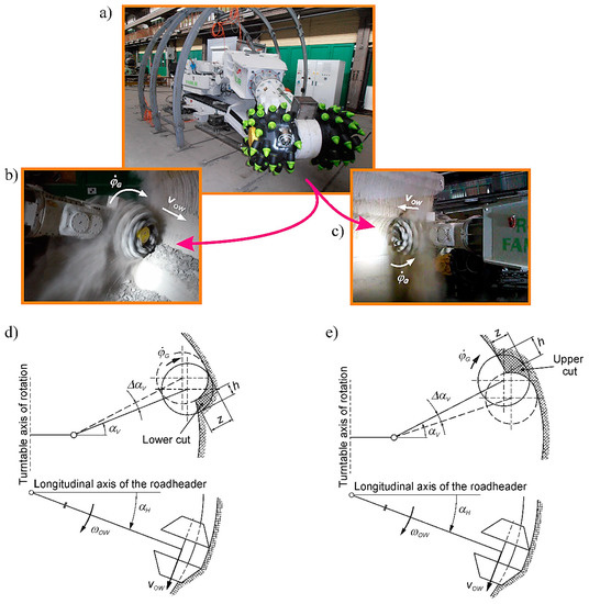
Figure 1.
Test object: (a) roadheader R-130 (manufactured by Famur SA) on the experimental stand, (b) the course of the lower cut, (c) the course of the upper cut, (d) parameters characterizing the lower cut, and (e) parameters characterizing the upper cut.
The dynamic characteristics registered during the experimental tests, which were conducted on the experimental stand described above, were first of all used to validate the original models developed for simulating the roadheader dynamics during mining, as written in the Matlab/Simulink and Embarcadero RAD Studio software. The cut surface was scanned before and after each cut, to link the dynamic response of the R-130 roadheader with the conditions of the cutting process. For this purpose, a Faro Focus3D X 130 HDR geodetic laser scanner was used, and the clouds of points thus obtained were processed in the Faro Scene, GOM Inspect, and Geomagic Design X software. This enabled the determination of the shape and size of the cross-section of cuts at any time and identify the excavated layers as well as their mechanical properties [28]. The experimentally verified simulation models were used for:
- −
- determining the control characteristics of the tested roadheader,
- −
- developing the structure of the automatic control system as well as the automatic control algorithm,
- −
- conducting computer tests on the behavior of a roadheader equipped with an automatic control system to analyze the movement of cutting heads during simulated mining of rocks with different mechanical properties.
A simplified block diagram depicting the automatic control system proposed for the boom-type roadheader is shown in Figure 2. The method of automatic control and the criteria for controlling the parameters of the cutting process are described extensively in the article [29]. The computer-determined control characteristics indicated that due to the adopted objective functions (the control criteria)—minimization of mining energy consumption and reduction of dynamic load on the roadheader—control is necessary for three of the four cutting process parameters listed. During the rock cutting process, the angular velocity of the cutting heads () resulting from the rotational speed of the motor rotor (n), their movement speed (vOW), and the height of the cut made (h) are changed programmatically. The fourth parameter, i.e., the web of cut z, is treated as a stochastic quantity and is therefore not expected to be measured in the final technical solution of the automatic control system.
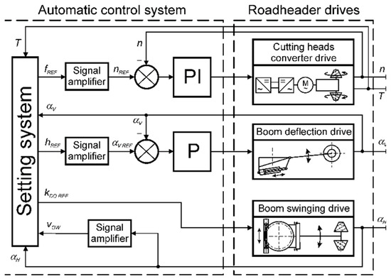
Figure 2.
A simplified diagram of the automatic control system developed for controlling the cutting heads movement of a boom-type roadheader according to the proposed concept: n—rotational speed of the motor rotor driving the cutting heads, vOW—movement speed of the cutting heads, αH & αV—boom deflection angles in a plane parallel and perpendicular to the floor.
Similar to the web of cut, the parameters that describe the mechanical properties of the excavated rocks in the cross-section of the drilled excavation are treated stochastically. Therefore, in real conditions, the workability of rocks need not be monitored, especially because the parameters describing their mechanical properties may vary to a large extent, both on the heading face and along the excavation length. It is also assumed that the execution of a given cut begins at a certain initial height hS, which results from the assumed change in the boom deflection angle in a plane perpendicular to the floor Δ at the sidewall of the excavation. The initial height of the cut need not be optimal at all. The task of the control system is to work out, in real-time, a favorable (due to the adopted target function) association of the cutting process parameters based on the historical information (in the previous rotation of cutting heads) on the dynamic load of the cutting heads drive (an adjustable value): {, vOW REF, hREF} = f(T). The aim of this task is to achieve the fastest possible cutting heads movement speed, , to ensure low mining energy consumption.
In the developed automatic control system, the setting system is responsible for working out the current values of the cutting process parameters. The system carries out specific mathematical procedures for determining the values of the cutting process parameters. At the same time, along with the dynamic load of the cutting heads drive (which reflects the dynamic state of the roadheader), the movement speed of the cutting heads is monitored. As indicated in the designated control characteristics [30,31], certain ranges of this speed, at which the dynamic load condition of the roadheader varies significantly, can be distinguished. This effect requires an appropriate approach to control when accelerating the cutting heads at the beginning of each cut (when the speed vOW increases from zero) and when braking them at the end of the cut (when the speed vOW decreases again to zero). Three speed ranges are considered for cutting heads as follows [29]:
- −
- the low boom swinging speed range (vOW = 40 to ~100 mm/s),
- −
- the medium boom swinging speed range (vOW = 100–175 mm/s) and
- −
- the high boom swinging speed range (vOW = 175–270 mm/s).
The reference values of the cutting process parameters developed by the setting system are implemented by the roadheader’s drivers (Figure 2):
- −
- The angular speed of the cutting heads is changed using a frequency converter supplying the drive motor in the roadheader’s cutting system. This parameter is adjusted in a closed feedback loop using the PI controller, based on the reference frequency of the supply voltage fREF.
- −
- The movement speed of the cutting heads (the boom swinging speed) vOW is changed by the controlled opening of the electrohydraulic valve in the power supply system of the actuator in the boom swinging mechanism (adjusted in an open feedback loop), based on the reference value of its opening factor kDO REF.
- −
- The height of the cut performed h is changed (corrected) by changing the boom deflection angle in a plane perpendicular to the floor ΔαV, using an electrohydraulic valve in the power supply system of the actuator in the boom deflection mechanism. This parameter is adjusted in a closed feedback loop using the P controller, based on the reference value of the boom deflection angle αV REF.
The control algorithm considers the following five cases of dynamic load status of the cutting heads drive, for which separate control procedures are performed [32]:
- −
- Case 1: the state of excessive load—the average torque on the motor shaft in the cutting heads drive (determined in the period of subsequent cutting head rotations) is 20% higher than the nominal value developed by this driving motor (), whereas no drive dynamic overload occurs;
- −
- Case 2: the underload—the average torque on the motor shaft in the cutting heads drive is 20% lower than the nominal value developed by this driving motor ();
- −
- Case 3: the state of nominal load—the average torque on the motor shaft in the cutting heads drive is in the band with a width of ±20% of the nominal value developed by this electric motor (), whereas no drive dynamic overload occurs;
- −
- Case 4: the state of dynamic overload—the instantaneous values over the next rotations of the cutting heads exceed the allowable value determined by the number of dynamic overload kd (), where the number of these exceedances (NE) is higher than the allowable NEmax value (determined by analyzing the dynamic properties of the cutting heads drive in the R-130 roadheader: kd = 2 and NEmax = 500);
- −
- Case 5: the state of low energy consumption during mining—in the range of high boom swinging speed, the lowest possible mining energy consumption is achieved by selecting the appropriate combination of process parameters required to meet this goal.
Because the process of cutting the heading face of a drilled excavation is not stationary (even if a rock with unchanging mechanical properties was being cut), achieving the desired dynamic loading states of the roadheader (Case 5 or Case 3) is tough and requires skillful correction of the values of the controlled parameters. This is even more complicated when the rock formation consists of rock layers characterized by strongly differentiated mechanical properties.
3. Analysis of the Behavior of a Roadheader Equipped with an Automatic Control System When Mining Rocks of Different Uniaxial Compressive Strengths
Operation of the control system with the proposed structure was tested during simulated cutting of rock with a uniaxial compressive strength σC of 20 (soft rock), 45 (medium rock), and 70 MPa (hard rock). Simultaneously, bottom cuts with an initial height hS of 150 mm were simulated with a maximum web of cut (zmax: 200 mm—for σC = 20 MPa and 100 mm—for σC = 45 and 70 MPa). In the computer simulations of easy-to-cut rocks, the web of cut value was two times higher than in the other cases. The dynamic loading of the cutting system for zmax = 100 mm was so small (even for the maximum cutting height) that it was impossible to meet the adopted control criteria.
The setting system determined the set values of the cutting process parameters {fREF, kDO REF, hREF} for subsequent rotations of the cutting heads, selecting the appropriate cases based on the size and nature of the dynamic load of the roadheader’s cutting system (Table 1). The set cut height, hREF, depends on the uniaxial compressive strength of the mined rocks (Figure 3a). In the range of low boom swinging speed (cutting head rotations 1–3 for σC = 70 MPa and rotations 1–4 for σC = 20 and 45 MPa), the setting system increased the cut height for all the considered rock types. However, this increase was smaller if the rock’s uniaxial compressive strength was higher. In the range of medium boom swinging speed (cutting head rotations 4–7 for σC = 70 MPa and rotations 5–7 for σC = 20 and 45 MPa), the cut height worked out by the setting system decreased. The higher the uniaxial compressive strength of the excavated rocks, the more significant the decrease in cut height. On the other hand, in the range of high boom swinging speed (from the eighth rotation of the cutting heads), the cut height value set by the setting system (hREF) increased and stabilized after some time at about 230 mm (for σC = 45 MPa) to about 190 mm (for σC = 70 MPa).

Table 1.
Set values of the cut height determined by the setting system and dynamic load cases of cutting heads drive for various uniaxial compressive strengths of mined rocks in subsequent rotations of the cutting heads.
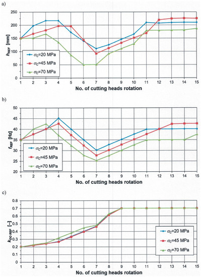
Figure 3.
Setpoint values worked out by the setting system: (a) cut height (hREF), (b) supply voltage frequency (fREF), and (c) opening coefficient of the electrohydraulic valve (kDO REF) in subsequent rotations of the cutting heads when making lower cuts in automatic mode in rocks with different uniaxial compressive strengths.
An increase in the cut height by the setting system in the range of low boom swinging speed was accompanied by an increase in the frequency of the motor supply voltage fREF in the cutting system (Figure 3b). In the case of hard-to-cut rock, the set value of this parameter grew faster than for the other rocks tested. In the ranges of medium and high boom swinging speed, the setpoint frequency of the motor supply voltage was smaller if the uniaxial compressive strength of the rock was higher (although in the final phase of the simulation, the value of fREF developed for the medium rock slightly exceeded that determined for the soft rock).
During the first nine rotations of the cutting heads (lasting for about 9.5 s), a systematic increase occurred in the degree of opening of the electrohydraulic valve in the supply system of the boom swinging actuator. The set opening coefficient value of this valve, kDO REF, increased from 0.2 (the minimum value resulting from the sensitivity of the modeled electrohydraulic valve) to 0.7 (the assumed maximum value). As we can see, the course of the variability of kDO REF in the first mining phase is approximationally parabolic. In all the analyzed cases, after the electrohydraulic valve was opened to the maximum degree, the cutting heads were moved at a speed of up to 270 mm/s, regardless of the uniaxial compressive strength of the excavated rocks. This was achieved by ensuring optimal conditions for the rock cutting process with mechanical properties assumed over a wide range of vOW speed variations. Thanks to the skillful selection of the frequency of the supply voltage and the cut height as the movement speed of the cutting heads increased, the excessive dynamic load of the roadheader’s drives, which occurs in the range of medium boom swinging speed, was avoided. Starting from the 11th (for σC = 20 and 70 MPa) and the 13th rotation of the cutting heads (for σC = 45 MPa), the state of low mining energy consumption was reached (Case 5; Table 1).
The average torque values on the motor shaft Tm during the simulated mining of soft, medium, and hard rocks varied to a large extent, especially in the ranges of low and medium boom swinging speed (Figure 4a). During the cutting of hard rock (green bars), the dynamic load of cutting heads drive was significantly higher in the range of low boom swinging speed compared to that obtained for soft and medium rocks, despite the lower cutting height. On the other hand, in the range of high boom swinging speed, starting from the 12th rotation of the cutting heads, the average torque values on the motor shaft were more evenly balanced, for all the types of rocks analyzed. However, the values were around the lower range limit considered as the state of nominal load.
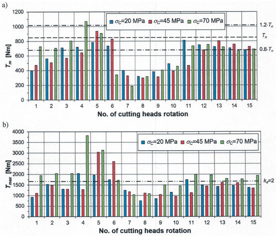
Figure 4.
The course of: (a) the average value (Tm) and (b) the peak value (Tmax) of torque on the motor shaft in the cutting heads drive in subsequent rotations of the cutting heads when making lower cuts in the automatic control mode in rocks with different uniaxial compressive strengths.
The peak torque values on the motor shaft Tmax in the cutting system were higher during the simulated mining of hard rock (σC = 70 MPa) compared to the peak values of dynamic load noted for other types of rocks, in the entire range of boom swinging speed (Figure 4b). If the number of exceedances (NE) of the set maximum torque on the motor shaft (determined by the number of dynamic overload kd) was higher during the subsequent rotations of cutting heads than the permissible value (NEmax), the set values of the cutting process parameters were determined by the setting system using the procedure for the dynamic overload state (Case 4). In the analyzed simulations, this case occurred for the medium rock (σC = 45 MPa) during the fifth and sixth rotations of the cutting heads, and for the hard rock (σC = 70 MPa) during the fourth and fifth rotations (Table 1). During the remaining rotations, even when the instantaneous torque on the motor shaft in the cutting heads drive exceeded the assumed permissible level (T > kd·Tn), the number of exceedances remained lesser than NEmax. As a result, control procedures were carried out for the other load cases of the cutting heads drive. A small number of exceedances (<500/rotation) of the permissible level is not dangerous in terms of the roadheader’s behavior during operation.
Figure 5 shows the time course of torque on the motor shaft (T) and its angular velocity () from the initiation of the cutting process to the stabilization of the dynamic loads of the roadheader, for the three analyzed types of mined rocks. Here, one can see (especially for σC = 45 and 70 MPa) the passage, along with the increase in the movement speed of the cutting heads, through the area of clearly higher dynamic loads, in the range of average boom swinging speed. Oscillations of the dynamic load of increased intensity, lasting <2 s, were quickly quenched by appropriately correcting the angular speed of cutting heads and cut height. In this way, it was possible to proceed to the range of high boom swinging speed (vOW > 175 mm/s). Therefore, there was no hindrance in the range of low boom swinging speed, or an uncontrolled decrease in cut height due to boom lifting (after exceeding the allowable load of its deflecting actuators), or loss of roadheader’s stability. For all the three uniaxial compressive strengths tested, the transient state lasted for up to 11 s of simulation. After achieving the optimal combination of values of the controlled parameters, in given conditions, the course of the dynamic load had a much-stabilized character, with a constant, approximately average value and amplitude.
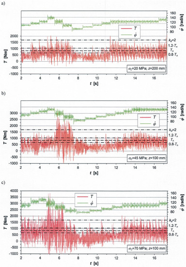
Figure 5.
Time courses of dynamic load on the motor shaft (T) and its angular velocity () when making lower cuts in the automatic control mode in rocks with uniaxial compressive strength (σC) of: (a) 20 MPa, (b) 45 MPa, and (c) 70 MPa (the figures show the web of cut values for which cutting was simulated).
Depending on the web of cut, cut height, and boom swinging speed, the mining efficiency Q varied greatly according to the uniaxial compressive strength of the rock being mined (Figure 6a). The highest efficiency was obtained for the soft rock (σC = 20 MPa), due to the twice higher web of cut compared to the other two considered rocks. In the ranges of medium and high boom swinging speed, the lowest mining efficiency was obtained in the subsequent rotations of cutting heads for the hard rock (σC = 70 MPa) (green line). This was due to the lower cut height. In all the cases studied, as the movement speed of the cutting heads increased, the mining efficiency tended to increase. The highest capacities corresponded to the high values of speed vOW, achieved from the 12th rotation of the cutting heads. In the case of soft rock (σC = 20 MPa), the maximum mining efficiency ranged from 35 to 38 m3/h (blue line). In turn, for σC = 45 and 70 MPa, the maximum mining efficiency was in the range of 15–20 m3/h (red and green line). Thus, it is possible to realize the actual impact of the web of cut, apart from the movement speed of the cutting heads, at which the cutting process is carried out, on the mining efficiency. However, when mining hard rock, achieving a high web of cut may not be possible, due to the excessive dynamic load on the roadheader.
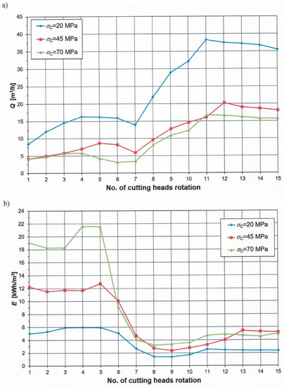
Figure 6.
The course of: (a) mining efficiency (Q) and (b) mining energy consumption (E) in subsequent rotations of the cutting heads when making lower cuts in the automatic control mode in rocks with different uniaxial compressive strengths.
Differentiated mining efficiency had a significant impact on the energy consumption E of mining rocks with different uniaxial compressive strengths (Figure 6b). The lowest values of this parameter, which did not exceed 6 kWh/m3 in the whole tested time interval, were obtained for σC = 20 MPa. Starting from the 11th rotation of the cutting heads, i.e., the time when the highest mining efficiency was obtained, the energy consumption of mining was at the level of 2.5 kWh/m3.
In the ranges of low and medium boom swinging speed, the mining energy consumption for rock with a uniaxial compressive strength σC of 45 MPa reached 13 kWh/m3, and for rock with a σC of 70 MPa it reached up to 22 kWh/m3. The maximum values of energy consumption for these rocks were 2- and over 3.5-fold higher, respectively, compared to energy consumption for mining rock with a uniaxial compressive strength of 20 MPa. In the range of high boom swinging speed, the mining energy consumption for medium and hard rock (σC = 45 and 70 MPa) did not exceed 6 kWh/m3. Despite the varied mining efficiency of these rocks in the range of high boom swinging speed, equalization of mining energy consumption seemed possible. This was because the simulated mining of rock with a uniaxial compression strength σC of 70 MPa was carried out at a lower angular speed of the motor rotor in the cutting system (at a lower frequency of the supply voltage). As a result, the power consumed to cut this rock was smaller. The average values of mining energy consumption determined for the entire cut varied as follows:
- −
- Em = 3.3 kWh/m3—for soft rock (σC = 20 MPa),
- −
- Em = 6.9 kWh/m3—for medium rock (σC = 45 MPa) and
- −
- Em = 9.7 kWh/m3—for hard rock (σC = 70 MPa).
To assess the efficiency of mining rocks of different workability with the R-130 roadheader equipped with the developed automatic control system, simulations of the cutting process were carried out in manual and automatic modes for comparison. Mining of rock with a uniaxial compressive strength of 20–70 MPa was simulated. In the manual mode, a constant (nominal) angular velocity of the cutting heads was assumed ( = 9.24 rad/s), corresponding to the power supply of the engine in the cutting heads drive from the mine electrical network with a voltage frequency f = 50 Hz. In both the control modes, the simulated cutting process began with the same values of a web of cut and cut height (zmax = 200 mm for σC = 20 MPa, 150 mm for σC = 30 MPa and 100 mm for σC = 45; h = 150 mm). In the manual mode, the degree of opening of the hydraulic valve in the supply system of the boom swinging actuator was selected such that the overloading of the cutting heads drive, the boom-swinging actuator, and the boom-deflecting actuators was prevented. This in turn allowed ensuring the possibility of carrying out the cutting process with specified values of a web of cut (z) and cut height (h) and with the highest possible movement speed of the cutting heads in working motion (vOW), at which:
- −
- the motor driving the cutting heads will not stop (stall),
- −
- the average load of the boom-swinging actuator will not exceed the maximum value resulting from its supply pressure and
- −
- the average load of the boom-deflecting actuators will not exceed the permissible value resulting from the settings of the safety valves.
Figure 7 compares the relationships of indicators characterizing the cutting process from the energy side and the load status of the roadheader’s drives responsible for performing the cutting process and the uniaxial compressive strength of the mined rock during simulated cutting in automatic (solid lines) and manual mode (dashed lines). As we can see, the relationships studied are nonlinear. Only in the case of mining of the soft rocks in manual and automatic mode did the tested characteristics seem to be located close to each other. This means that for easily workable rocks, the adopted control strategy does not significantly improve the indicators characterizing the course of the cutting process. However, the benefits of the control method used are increasingly apparent as the rock’s uniaxial compressive strength increases. The average mining energy consumption determined for the entire cutting performed in the automatic mode ranged from 82% (for σC = 20 MPa) to 66% (for σC = 70 MPa) which is the value obtained during cutting in the manual mode (Figure 7a). Thus, this suggests that the applied automatic control strategy allowed up to a one-third reduction in the average energy consumption. In addition, the power demand for cutting in the automatic mode was noticeably lower (Figure 7b). In the studied range of variability of the rock’s uniaxial compressive strength, the average power consumed for cutting in automatic mode varied within a relatively narrow range, from 68 to 76 kW. On the other hand, in the manual mode, the power intensively increased with an increase in σC value, reaching 180 kW. Because comparing the power consumed in the mining process when using a converter drive can be misleading, in Figure 7c,d, the average and peak values of dynamic load are compared to the motor shaft in the cutting heads drive. In both cases, with an increase in the rock’s uniaxial compressive strength, the lines mapping the relationships Tm = f(σC) and Tmax = f(σC) for manual and automatic modes were increasingly moving apart. In the case of automatic mode, the average Tm value was at an approximately constant level (about 620 Nm) for rocks of different workability. On the other hand, during manual control, the value of this parameter grew intensively between 657 and 1.156 Nm. Therefore, for the rock with the highest σC value, the average load of the cutting heads drive during mining in the manual mode was over 80% higher compared to that recorded in the automatic mode. The peak dynamic load Tmax of cutting heads drive in both manual and automatic mode increased with an increase in the uniaxial compressive strength of the rock. However, the peak increase during manual control was more significant. For the highest uniaxial compressive strength tested (σC = 70 MPa), the peak dynamic load of a motor in the cutting heads drive was almost 40% higher in the manual mode than the value obtained during simulated mining in the automatic mode.
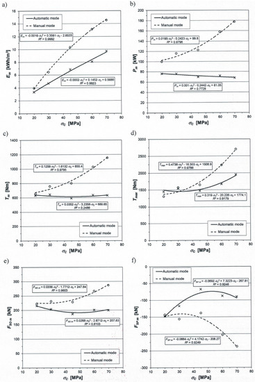
Figure 7.
Comparison of the relationship: (a) average cutting energy consumption (Em), (b) average cutting power (Pm), (c) average torque on the motor shaft in the cutting heads drive (Tm), (d) peak torque on the motor shaft in the cutting heads drive (Tmax), (e) average load of the boom swinging actuator (FSO m), and (f) average load of the boom deflection actuators (FSP m) from the uniaxial compressive strength of the rock being mined for simulated cutting in automatic control mode (solid lines) and manual control mode (dashed lines).
The benefits of the algorithm used to control the cutting heads’ movement of a boom-type roadheader are shown as histograms of the distribution of the torque values on the motor shaft in the cutting heads drive for selected uniaxial compression strengths of rock (Figure 8). In all cases considered here, the dominant torque values T are shifted downwards. For example, in the case of automatic mining of rock with a uniaxial compressive strength σC of 20 MPa, the values of this load in the range from 250 to 500 Nm had the largest share (26%) (Figure 8a). In turn, for the simulated mining of the same rock in the manual mode, the values ranging from 500 to 750 Nm had the largest share (29%) (Figure 8b). Similarly, for σC = 70 MPa, during mining in the automatic mode, the largest share was constituted by torque values on the motor shaft ranging from 500 to 750 Nm (Figure 8e). On the other hand, during mining in the manual mode, the values from 750 to 1000 Nm had the most significant share (Figure 8f). The histograms of the distribution of the examined dynamic load revealed its dominant ranges. Thus, in the case of mining in the automatic mode, the values of this load ranging from 250 to 750 Nm dominated for all uniaxial compressive strengths of the rock being mined (Figure 8a,c,e). The shares of values in this range extended from 39% (for σC = 70 MPa) to about 50% (for σC = 20 and 45 MPa). During cutting in the manual mode, the dominant ranges of the dynamic load of a motor in the cutting heads drive were broader. Thus, for σC = 20 MPa, as much as 85% of the set of values of this load was in the range from 250 to 1000 Nm (Figure 8b). In the case in which the uniaxial compressive strength of the cut rock was 45 MPa, the torque values, T, ranging from 500 to 1250 Nm had the largest share (Figure 8d), and for σC = 70 MPa, the values of this load dominated from 750 to 1500 Nm (Figure 8f). They accounted for more than half of the values in the course of this load for the entire cut.
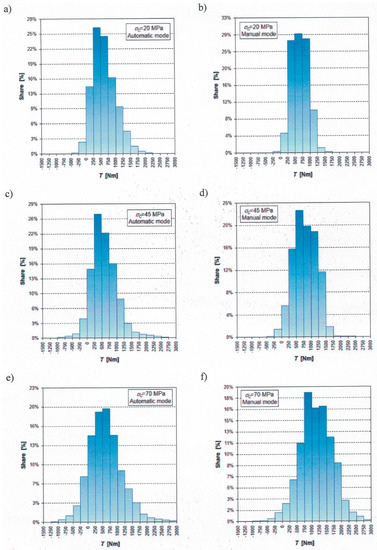
Figure 8.
Histograms of the torque value distribution on the motor shaft in the cutting heads drive during simulated rock mining with three different uniaxial compressive strengths in (a,c,e) automatic control mode and (b,d,f) manual control mode.
The average values of the dynamic load of both the actuator in the boom swinging mechanism (Figure 7e) and the actuators in the boom deflection mechanism (Figure 7f) during the simulated rock mining in automatic and manual modes did not exceed the permissible values. Without this condition, it would not be possible to carry out the cutting process with the given values of its parameters. However, in the case of mining in automatic mode, the load on the boom deflection mechanisms was lower. The average load of the boom swinging actuator (FSO m) determined along the entire cut length, in the tested range of the uniaxial compressive strength of rock (from 20 to 70 MPa), varied from 187 to 215 kN in the automatic mode and from 223 to 287 kN in the manual mode.
In the case of manual control, the average value of this load increased with the increase in the uniaxial compressive strength of the rock being mined. For automatic control, the course of the relationship FSO m = f(σC) had a minimum for σC = 45 MPa (Figure 7e, solid line). The highest average load of the boom swinging mechanism was recorded for the smallest σC value. This proves that not only the mechanical properties of the rock being mined but also the cutting process parameters determine the level of load on the roadheader drives responsible for performing the cutting process (the course, the relationship T = f(σC) also has a similar characteristic). In the case of automatic mode mining of the rock with the highest uniaxial compressive strength among the tested values, the average dynamic load of the actuator in the boom swinging mechanism was 30% lower compared to that obtained for simulated mining of the same rock in the manual mode.
The impact of the method used for controlling the cutting heads movement is even more visible in the course of dependence of the average dynamic load value of boom deflection actuators on the uniaxial compressive strength of the rock being mined: FSP m = f(σC) (Figure 7f). Negative values of this load mean that the boom deflection actuators are stretched under the effect of an external load. This is because the lower cuts were simulated. In such a case, with the down-cut rotation of the cutting heads and the relatively low cut height, the reaction forces of the cut rock acting on the boom are directed upwards.
While mining in the manual mode, with the increase of (σC value, the average dynamic load of boom deflection actuators intensively increased (Figure 7f, dashed line) approaching the permissible level (FSP LIMIT = −250 kN). In the examined range of variability of the uniaxial compressive strength of the rock being mined, the mean value of the FSP force ranged from −138 to −237 kN. On the other hand, the course of the relationship considered here for mining in the automatic mode (solid line) looks different. In this case, as (σC increased, the load (absolute value) initially decreased, and after reaching the local minimum (for (σC = 45 MPa), it increased slightly. The value of this parameter changed from −150 to −68 kN. For example, comparing the results obtained for σC = 70 MPa, it can be seen that while mining in the automatic mode the average dynamic load of the boom deflection actuators was over 60% smaller compared to that obtained during mining in the manual mode.
4. Numerical Tests of the Behavior of Roadheader during the Mining of Rock with Variable Uniaxial Compressive Strength in the Automatic Mode
When drilling roadways in underground mines or communication tunnels, one rarely deals with a situation in which a homogeneous rock with constant mechanical properties is cut throughout the entire cross-section of the excavation, and even along the length of the subsequent cuts. Most excavations are drilled in a rock formation having a layered structure, in which layers of hard-to-cut rocks are separated by layers of easy-to-cut rocks. Therefore, while making subsequent cuts with the cutting heads of a roadheader, there is a chance of encountering changing external conditions of the mining process. As the cutting heads move from one rock layer to another, the mechanical properties of the mined rock mass, including the average uniaxial compressive strength, change.
To examine the behavior of the roadheader equipped with the proposed automatic control system for controlling the cutting heads’ movement and to determine the potential benefits of its use, computer simulations were carried out for the process of mining of layered rock mass in the automatic mode. For this purpose, a situation in which the cutting heads pass through two rock layers with profoundly different workability was examined (Figure 9). The uniaxial compressive strength of these layers was: σC1 = 20 MPa and σC2 = 70 MPa, respectively. The layers were inclined transversely to the excavation floor at an angle α1 = α2 = 20°, and their thickness measured in the axis of the drilled excavation was: h1 = 1.5 m and h2 = 5.5 m, respectively. The following two cases were investigated (Figure 9):
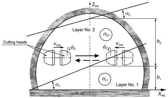
Figure 9.
Scheme of mining a rock mass with a layered structure using parallel cuts to the floor of the drilled roadway.
- −
- mining while swinging the boom to the right (solid line) and
- −
- mining while swinging the boom to the left (dashed line).
In the first case, the cutting process was initiated in the rock with a uniaxial compressive strength of 70 MPa, and as the cutting heads moved, this strength decreased until it reached a value of 20 MPa. In the second case, the situation was the opposite, i.e., the mining began in the rock with a uniaxial compressive strength of 20 MPa and ended in the rock with a uniaxial compressive strength of 70 MPa. In both cases, the cutting was simulated with the web of cut zmax = 200 mm and the initial height of the lower cut hS = 150 mm. Using the developed algorithm of automatic control, the setting system worked out the set values of the cutting process parameters {fREF, kDO REF, hREF} for the subsequent rotations of the cutting heads. This was done by implementing the appropriate procedures selected based on the size and nature of the dynamic load course of the motor in the tested roadheader’s cutting system (Table 2).
Table 2.
Set values of the cutting process parameters determined by the setting system during simulated mining of rocks with variable uniaxial compressive strength.
Figure 10, Figure 11 and Figure 12 show the results of computer simulation of the mining process for the first case (σC = 70→20 MPa). The cutting process was carried out during 18 rotations of the cutting heads. During the first six rotations (about 5.5 s), the rock with a uniaxial compressive strength of 70 MPa was mined. During the next five rotations (4.6 s), the rock mass with a variable compressive strength was mined. This was due to the transition of the cutting heads to a layer with a uniaxial compressive strength of 20 MPa. The cutting heads made the next seven rotations during the mining of rocks with the lower uniaxial compressive strength mentioned. The course of the average uniaxial compressive strength of the rock mass being mined is marked with a green line in Figure 11b.
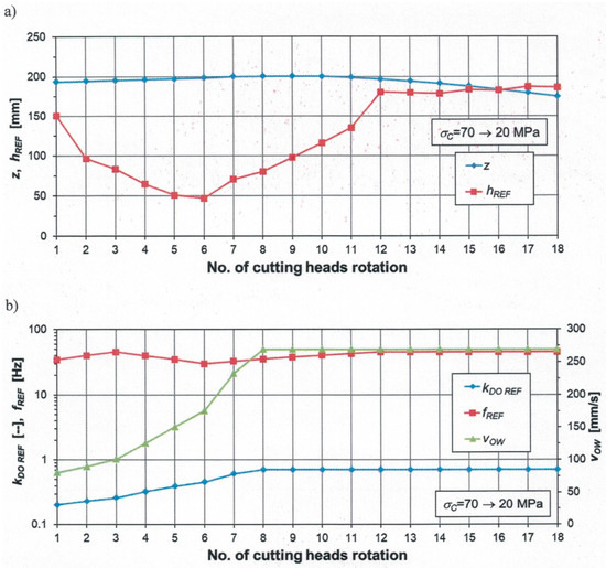
Figure 10.
The course of cutting parameters: (a) web of cut (z) and set cut height (hREF) and (b) cutting heads movement speed (vOW), and set values: supply voltage frequency (fREF) and electrohydraulic valve opening coefficient (kDO REF) in subsequent rotations of the cutting heads when making lower cuts in the automatic control mode in rocks with decreasing uniaxial compressive strength.
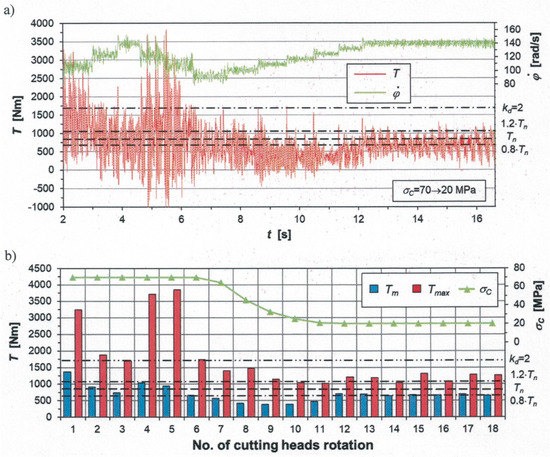
Figure 11.
(a) Time courses of dynamic load on the motor shaft in the cutting heads drive (T) and its angular velocity () and (b) values of parameters characterizing this load in subsequent rotations of the cutting heads during the performance of lower cut in the automatic control mode in rocks with decreasing uniaxial compressive strength.
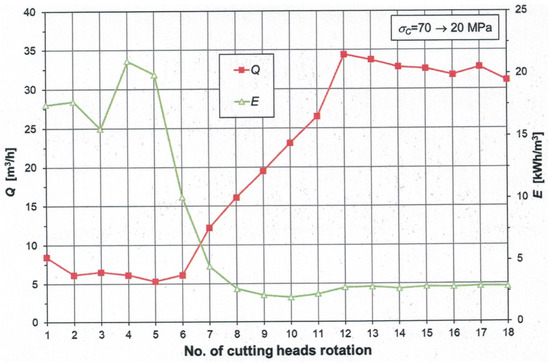
Figure 12.
Mining efficiency (Q) and energy consumption (E) in subsequent rotations of the cutting heads during the performance of lower cut in the automatic control mode in rocks with decreasing uniaxial compressive strength.
In the range of low boom swinging speed (cutting head rotations of 1–3), the setting system increased the boom swinging speed (vOW) by increasing the opening coefficient of the electrohydraulic valve in the supply system of the boom swinging actuator (kDO REF). At the same time, the angular velocity of the cutting heads was increased by an increase in the frequency of the motor supply voltage in the cutting system (fREF) (Figure 10b). The cut height was quite significantly reduced by almost half from the initial value to hREF = 83 mm (Figure 10a). In the range of medium boom swinging speed (cutting head rotations 4–6), the setting system continued to increase the kDO REF value, which resulted in a further increase in the boom swinging speed. In the sixth rotation of the cutting heads, this speed reached the level of 175 mm/s (for kDO REF = 0.45). During this period, the angular velocity of the cutting heads was reduced due to a decrease in the frequency of the motor supply voltage in the cutting heads drive (ranging from 45 to 30 Hz). The cut height continued to decrease and reached the lowest value of 47 mm in the sixth rotation of the cutting heads. In the range of high boom swinging speed (starting from the cutting head rotation 7), where high efficiency and low energy consumption are sought, the setting system increased the boom swinging speed by increasing the opening coefficient of the electrohydraulic valve in the supply system of the boom swinging actuator to the assumed maximum value (kDO REF = 0.7). This value was already achieved in the eighth rotation of the cutting heads. From this point, the cutting heads were moved at the maximum achievable speed. The angular velocity of the cutting heads was also gradually increased as a result of an increase in the frequency of the motor supply voltage in the cutting system to fREF = 45 Hz. Due to the decrease in the uniaxial compressive strength of the excavated rocks, the setting system increased the cut height, which reached the value of hREF = 180 mm in the 12th rotation of the cutting heads (Table 2). Therefore, after stabilizing the values of the cutting process parameters, the cut height was 20% higher than the initial value.
In the initial stage of cutting (in the ranges of low and medium boom swinging speed), mining of rock with a uniaxial compressive strength of 70 MPa was accompanied firstly by a decrease in the dynamic load of the cutting heads drive and then by its increase (Figure 11). The average and peak torque values on the motor shaft of the cutting system (determined during the subsequent rotations of the cutting heads) systematically decreased during the first three rotations of the cutting heads, reaching the level: and (Figure 11b). At the same time, the setting system carried out the procedure of determining the cutting process parameters for Case 4, and during the third rotation of the cutting heads, it carried out the procedure for Case 3. When the range of the medium boom swinging speed was reached, the peak torque on the motor shaft exceeded the accepted dynamic overload. In the fifth rotation, the peak value of this load reached 3850 Nm. Because the instantaneous dynamic loading values of the cutting heads drive exceeded the assumed permissible level (determined by the number of dynamic overload kd = 2) and the number of these exceedances (NE) was higher than the permissible value NEmax, the setting system carried out the procedure for determining the values of the mining process parameters for Case 4. This led to a decrease in the dynamic load on the cutting system. During subsequent rotations of the cutting heads, the decrease in the average uniaxial compressive strength of the extracted rocks led to the implementation of the procedure for Case 2 (the underload) during the next six turns of the cutting heads. The corrections made in the values of the cutting process parameter at that time resulted in a state of low energy consumption during mining (Case 5). The average load on the cutting heads drive fell below the lower allowable limit (Case 2), due to the decrease in the web of cut, as the boom was swinging toward the sidewall of the excavation. Hence, in the range of high boom swinging speed, the setting system periodically corrected the range of the cut height, thanks to which it was possible to return to the state of low energy consumption during mining (Case 5; Table 2).
In the first phase of mining, the mining efficiency Q was relatively low, ranging from 5.3 to 8.4 m3/h (Figure 12, red line). This was accompanied by high mining energy consumption E, in the range from 15.5 to 21 kWh/m3 (green line). However, in the range of high boom swinging speed, starting from the seventh rotation of the cutting heads (after about 5.5 s from the beginning of mining), the mining efficiency increased rapidly, and the mining energy consumption decreased. After optimizing the cutting process parameters to the conditions of its performance, the mining efficiency ranged from 31.8 to 34.4 m3/h and the energy consumption stabilized at 2.8 kWh/m3.
The computer simulation of mining in manual control mode was carried out to assess the effectiveness of the proposed automatic control algorithm in the mining of a layered rock massif. Similarly, as described in Section 3 of this article, mining was simulated at:
- −
- a fixed value of the angular velocity of the cutting heads, = 9.24 rad/s (the drive motor is powered directly from the power supply network with a frequency of 50 Hz);
- −
- the same parameters as for the automatic control, the initial web of cut values and the cut height; and
- −
- the manually controlled degree of opening of the electrohydraulic valve in the supply system of the boom swinging actuator, ensuring the possibility of carrying out mining with the fastest possible movement speed of the cutting heads.
It turns out that during the manual control, such high speeds of cutting heads cannot be achieved as during the automatic control implementing the adopted control strategy. As can be seen in Table 3, for the considered mining (σC = 70→20 MPa), the average value of the boom swing speed (vOW m), which was determined for the entire length of cut performed in the automatic control mode, was over 40% higher compared to the average speed during mining in the manual mode. This resulted in significantly higher efficiency (Qm) during mining in the automatic mode (by over 45%), which allowed reducing the average energy consumption (Em) by half. However, the reduction of mining energy consumption achieved in the automatic mode was not only due to an increase in the mining efficiency but also due to a decrease in the power consumed to carry out this process (Pm). For manual control, the average cutting power determined for the entire cutting was close to 133 kW and was thus at the nominal level of the motor in the tested roadheader. On the other hand, in the automatic control, the average cutting power was 35% lower, amounting to 86 kW. In this case, the reduction in power consumption was associated not only with a decrease in the average torque on the motor shaft in the cutting heads drive (by nearly 20%) but also with a decrease in the average angular speed of the cutting heads ) (by 20%). Furthermore, the dynamic load on the boom deflecting mechanisms during simulated mining in the automatic mode, especially the boom lifting mechanism, was more favorable. The average (FSP m) and peak (FSP max) dynamic loads of the actuators in this mechanism in the automatic mode were nearly 24% and 5% smaller, respectively than the corresponding values obtained for the manual mode.
Table 3.
Comparison of parameter values characterizing the process of rock mining with variable uniaxial compressive strengths during cutting in manual and automatic mode.
Figure 13, Figure 14 and Figure 15 show the results obtained for the computer simulation of the mining of a rock mass with a layered structure in the opposite direction (boom swinging to the left; Figure 9). The initial values of the cutting process parameters were the same as in the case described above.
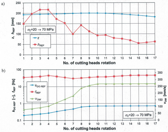
Figure 13.
The course of cutting parameters: (a) web of cut (z) and set cut height (hREF) and (b) cutting heads movement speed (vOW), and set values: supply voltage frequency (fREF) and electrohydraulic valve opening coefficient (kDO REF) in subsequent rotations of the cutting heads during the performance of lower cut in the automatic control mode in rocks with increasing uniaxial compressive strength.
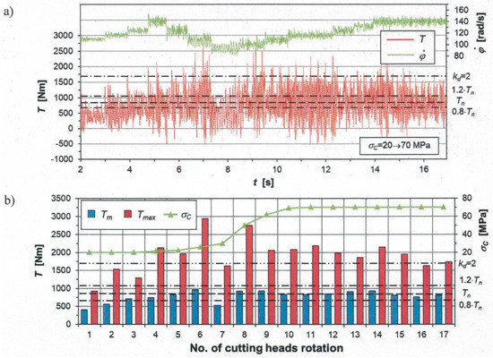
Figure 14.
(a) Time courses of dynamic load on the motor shaft in the cutting heads drive (T) and its angular velocity () and (b) values of parameters characterizing this load in subsequent rotations of the cutting heads during the performance of lower cut in the automatic control mode in rocks with increasing uniaxial compressive strength.
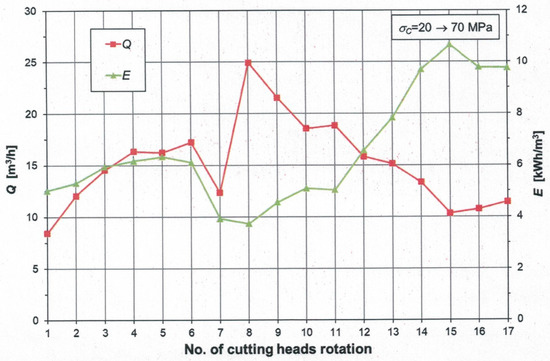
Figure 15.
Mining efficiency (Q) and energy consumption (E) in subsequent rotations of the cutting heads during the performance of lower cut in the automatic control mode in rocks with increasing uniaxial compressive strength.
In the range of low boom swinging speed, during the first three rotations of the cutting heads, mining took place in the layer with a uniaxial compressive strength σC of 20 MPa (Figure 14b, green line). However, as they moved, the cutting heads began to cut the rock with a uniaxial compressive strength σC of 70 MPa. As a result, during the subsequent rotations of the cutting heads, the average compressive strength of the excavated rock gradually increased, reaching the maximum value (70 MPa) in the 11th rotation. From this point, the cutting heads were mining rock with a constant uniaxial compressive strength of 70 MPa.
During the speed up of the cutting heads, in the range of low boom swinging speed (cutting head rotations 1–4), the setting system increased the values of all the three controlled parameters of the mining process (Figure 13, Table 2):
- −
- the cut height hREF up to 218 mm,
- −
- the angular velocity of the cutting heads by increasing the frequency of the motor supply voltage in the cutting system fREF to 45 Hz and
- −
- the boom swinging speed by increasing the degree of opening of the electrohydraulic valve kDO REF in the power supply system of the boom swinging actuator to 0.27.
In the range of medium boom swinging speed (cutting head rotations 5–7), the setting system continued to increase the degree of opening of the electrohydraulic valve in the supply system of the boom swinging actuator (by increasing kDO REF to 0.47), which led to a further increase in the boom swinging speed vOW. On the other hand, the angular velocity of the cutting heads was reduced as a result of reducing the frequency of the motor supply voltage in the cutting system to fREF = 30 Hz. Since the strongest dynamic loads occur in the range of medium boom swinging speed, the cut height was also reduced to hREF = 100 mm to limit these dynamic loads (Table 2).
In the range of high boom swinging speed (cutting head rotations 8–17), the setting system continued to increase the opening coefficient of the electrohydraulic valve to the maximum value (kDO REF = 0.7). As a result, the boom swinging speed reached its maximum value in the tenth rotation of the cutting heads. The frequency of the motor supply voltage in the cutting heads drive was also gradually increased to fREF = 45 Hz, as a result of which their angular velocity increased. Because during this time the rock’s uniaxial compressive strength increased sharply, the setting system reduced the height of the cut, stabilizing it at hREF = 60 mm in the final phase of the simulation.
Initiation of the cutting process in easily workable rock (σC = 20 MPa) resulted in a low, although systematically increasing, dynamic load on the cutting heads drive (Figure 14a). In the range of low boom swinging speed, the setting system initially carried out the procedure for determining the parameters of the mining process for Case 2 (underload) and then for Case 3 (nominal load). The average torque value on the motor shaft in the cutting system was initially <0.8·Tn and its maximum values did not exceed the set permissible level (Figure 14b). In the range of medium boom swinging speed, when the uniaxial compressive strength of the rock being mined began to increase gradually, the average torque on the motor shaft reached the nominal value. However, since the number of exceedances of the instantaneous torque value was higher than the assumed maximum value (NE > NEmax), the setting system carried out the procedure for the dynamic overload condition (Case 4). The increase in mining resistance resulting from the increase in the average uniaxial compressive strength of rock initially caused alternating conditions: the dynamic overload (Case 4) and the underload (Case 2). However, as the parameters of the mining process were tuned, the load condition of the cutting heads drive reached the nominal level (Case 3).
In the first phase of the analyzed cut (from the first to the eighth rotation of the cutting heads), the mining efficiency (Q) increased from 8.4 to 24.9 m3/h (Figure 15, red line). However, a sharp decrease in the cut height in the second part resulted in a decrease in the mining efficiency, although this process was performed at the high speed of the cutting heads. During subsequent rotations of the cutting heads, the mining efficiency systematically decreased to the level of 10–11 m3/h. Since at that time the simulated mining concerned hard-to-cut rock, such performance is not surprising. Therefore, the increase or decrease in the rock workability over the length of the cut performed significantly impacts the mining efficiency (Figure 12 and Figure 15). The average mining efficiency determined for the entire cutting, in the case when the uniaxial compressive strength of the rock mass decreased (σC = 70→20 MPa), was over 30% higher compared to that obtained for the rock massif with increasing uniaxial compressive strength (σC = 20→70 MPa; Table 3).
Due to the way the mining process was carried out, in the discussed case, the energy consumption (E) tended to increase in the subsequent rotations of the cutting heads (Figure 15, green line). At the initial stage of mining, this increase was small, in the range from 5 to 6.3 kWh/m3. After a decrease to the level of 4 kWh/m3 (during the eighth rotation of the cutting heads), a systematic increase was noted in the mining energy consumption, which exceeded the level of 10 kWh/m3 in the final phase of the simulated mining. Although the average mining efficiency (calculated for the entire cut) was lower compared to the previously discussed case, the average mining energy consumption for this cut was lower by about 10% (Table 3).
It is worth noting that the average movement speed of the cutting heads (vOW m), determined for the entire length of the cut, during the simulated mining of a layered rock mass (σC = 20→70 MPa) in the automatic mode was twice as high as that in the manual mode (Table 3). As a result, the mining efficiency (Qm) was over 60% higher. The power consumed during mining in the automatic mode was lower by about 30%. In the automatic control mode, the average cutting power (Pm) was at the level of 90 kW, while in the manual mode it was 135 kW. This resulted not only from the lower angular velocity of the cutting heads but also from a lower (by 12%) load level of the cutting heads drive. As a result, the average mining energy consumption (Em) was 6.6 kWh/m3. Similar to the previously described case, the automatic control of the cutting heads movement, according to the proposed method, contributed to improving the dynamic state of the boom deflection mechanisms.
5. Conclusions
The simulation tests conducted on the dynamics of the boom-type roadheader equipped with an automatic control system for controlling the movement of the cutting heads allowed the formulation of the following conclusions:
- (1)
- The results of the computer tests indicated the usefulness of the developed control algorithm due to the adopted objective functions (control criteria). The adopted control strategy allows for the reduction of the mining energy consumption as well as the dynamic loads on the cutting heads drive, the boom deflection mechanisms, and the roadheader’s body. With the programmable control of the cutting heads’ angular velocity and the skillful selection of the cut height, it is possible to mine even hard-to-cut rocks at the high speed of the cutting heads (boom swinging) in the working motion. During the speed up (at the beginning of the cut) and the slow down (at the end of the cut) of the cutting heads, it is possible to pass through the area of particularly high dynamic loads, which occurs in the range of medium boom swinging speed, by appropriately selecting the combination of values of these parameters, with proper control of the boom swinging speed. This prevents the blocking of drives, which are responsible for the rotation of the cutting heads and their movement on the heading face of a drilled roadway or a tunnel in the area of low swinging speeds. This effect occurs when a roadheader is controlled manually.
- (2)
- The effectiveness of the proposed control method is especially realized during the mining of hard and medium rocks. As clearly indicated by the results of the simulation tests, the lines mapping the dependencies of parameters characterizing the roadheader’s dynamic state and the associated results (dynamic load on the roadheader’s drives, mining energy consumption, power consumed for mining, mining efficiency) were obtained from the uniaxial compressive strength of the mined rocks, for the manual and automatic control modes diverge very much with the increase in the hardness of the mined rock. In turn, when mining soft rocks, these lines are located close to each other. This proves that the adopted control strategy has little impact on the mining of soft rocks. However, the priority is to ensure that the efficiency of hard-to-cut rock mining is high, as soft rock mining has never been a significant problem for roadheaders. The results of the computer tests indicated that mining of rock with a uniaxial compressive strength σC of 70 MPa (i.e., in the limits of application of the tested roadheader) in the automatic control mode allows reducing:
- −
- the energy consumption by up to one-third,
- −
- the average dynamic loads of the cutting heads drive by almost half and
- −
- the peak value of dynamic loads by nearly 30%.
These results are achieved because the dominant ranges of the variability of this load in the automatic control mode are shifted toward lower values. - (3)
- An essential issue faced with the automatic control of the cutting heads movement of a roadheader is the machine’s behavior during the mining of a layered rock mass, especially when the cutting heads transition between layers of very different workability. This situation is quite common due to the geological structure of the rock mass. Therefore, one of the objectives of testing the developed automatic control system was to examine the course of the mining process when changing the workability of the rock over the length of the cut. For this purpose, the results obtained for simulated mining of rocks with decreasing uniaxial compressive strength (σC = 70→20 MPa) and with increasing uniaxial compressive strength (σC = 20→70 MPa) in automatic and manual modes were compared. Significant benefits were found with the application of the proposed automatic control algorithm. The reduction achieved in the average mining energy consumption after the program control of the cutting process parameters was at the level of 47–63%, with a reduction in the average power used for mining by about 30–35%. Another important advantage of the developed automatic control system is a significant (even 2-fold) increase in the movement speed of the cutting heads on the heading face surface, which contributes to shortening the time taken for cutting the heading face of the drilled excavation or tunnel. The tangible benefit associated with this is an increase in mining efficiency by more than half.
- (4)
- In the case of cutting a rock mass with a layered structure, the efficiency of mining is affected by the direction of the rock workability gradient over the length of the cut. The results of the computer tests indicated differences in the mining process and the effects obtained. It turned out that the average movement speed of the cutting heads and the average cutting efficiency were higher when the uniaxial compressive strength decreased along the length of the cut (σC = 70→20 MPa). For mining in the automatic control mode, the values of these parameters with decreasing uniaxial compressive strength of the excavated rocks were higher by 7% and 34%, respectively, than those obtained during simulated mining of rocks with increasing uniaxial compressive strength. Despite this, the average energy consumption of mining was higher by about 14%.
- (5)
- The increase in the rock mining efficiency, anticipated based on the simulation tests carried out, resulting from the application of the developed algorithm for controlling the movement of the cutting heads, allows the broader use of boom-type roadheaders in drilling roadways and tunnels in hard-to-cut rocks. The efficiency of this type of machine in such conditions is very low, and so the blasting technique is commonly used for mining hard-to-cut rocks. Limiting the use of explosives in tunnel works would improve the safety of mining work and ensure greater stability of the support system of roadways and tunnels. The use of the blasting technique causes the rock mass surrounding the excavation to crack, which reduces its carrying capacity and increases the load on the support. The developed automatic control algorithm tested on the R-130 roadheader would also contribute to increasing the drilling speed of roadways by ensuring high cutting speeds.
Thus, the developed solution is another step toward the robotization of drilling roadways in underground mines and tunnels using boom-type roadheaders in civil engineering.
Funding
The work was conducted under the research project titled ‘Control of roadheader cutting heads movement for the reduction of energy consumption of mining and dynamic loads’, co-financed by the Polish National Center for Research and Development under the Applied Research Projects (agreement no. PBS3/B2/15/2015).
Acknowledgments
Publication supported under the rector’s pro-quality grant. The Silesian University of Technology, 06/020/RGJ21/0051.
Conflicts of Interest
The author declares no conflict of interest.
References
- Driesch, S.; Kleinert, H.-W. Maßnahmen zur Verbesserung der Wirtschaftlichkeit im maschinellen Vortrieb. Glückauf 1993, 129, 519–523. [Google Scholar]
- Sikora, W. (Ed.) Determination of Forces and Energy Consumption of Excavation with Conical Picks; The Silesian University of Technology Press: Gliwice, Poland, 2000. [Google Scholar]
- Advance Drivage and Roadheading Intelligent Systems (ADRIS)—Final Report; Publications Office of the European Union: Luxembourg, 2012.
- Yan, C.; Zhao, W.; Lu, X. A multi-sensor based roadheader positioning model and arbitrary tunnel cross section automatic cutting. Sensors 2019, 19, 4955. [Google Scholar] [CrossRef] [PubMed]
- Hekimoglu, O.Z. Comparison of longitudinal and transverse cutting heads on a dynamic and kinematic basis. Min. Sci. Technol. 1991, 13, 243–255. [Google Scholar] [CrossRef]
- Heiniö, M. (Ed.) Rock Excavation Handbook; Sandvik Tamrock Corp.: Tampere, Finland, 1999. [Google Scholar]
- Wang, X.; Chen, Y.; Fan, S.; Shi, M.-Q.; Gao, S.; Guo, Y. Design of boom-type roadheader remote monitoring and control system. In Proceedings of the Third International Conference on Mechanic Automation and Control Engineering, Baotou, China, 27–29 July 2012; pp. 2831–2834. [Google Scholar] [CrossRef]
- Bartoszek, S.; Kost, G. System for positioning of the roadheader in roadways in hard coal mines. In Mechatronics 2017—Ideas for Industrial Application; Świder, J., Kciuk, S., Trojnacki, M., Eds.; Springer: Berlin/Heidelberg, Germany, 2019; pp. 20–29. [Google Scholar] [CrossRef]
- Zhao, H.Q.; Wang, S.S. Visualization research of roadheader’s memory cutting research. Appl. Mech. Mater. 2010, 33, 177–180. [Google Scholar] [CrossRef]
- Peinsitt, T.; Haubmann, H.; Kargl, H. Recent developments towards autonomous tunneling and mining machinery. In Tunnels and Underground Cities: Engineering and Innovation meet Archeology, Architecture and Art; Peila, D., Viggiani, G., Celestino, T., Eds.; CRC Press/Balkema: London, UK, 2019; pp. 2849–2858. [Google Scholar]
- Yang, W.; Zhang, X.; Ma, H.; Zhang, G. Infrared LEDs-based pose estimation with underground camera model for Boom-type roadheader in coal mining. IEEE Access 2019, 7, 33698–33712. [Google Scholar] [CrossRef]
- Fuentes-Cantillana, J.L.; Catalina, J.C.; Rodriguez, A.; Orteu, J.-J.; Dumahu, D. Use of Computer vision for automation of a roadheader in selective cutting operation. In Proceedings of the International Symposium on Mine Mechanization and Automation, Golden, CO, USA, 10–13 June 1991; pp. 15-1–15-10. [Google Scholar]
- Orteu, J.-J.; Catalina, J.-C.; Devy, M. Perception for a roadheader in automatic selective cutting operation. In Proceedings of the IEEE International Conference on Robotics and Automation, Nice, France, 12–14 May 1992; pp. 626–632. [Google Scholar] [CrossRef]
- Catalina, J.C.; Artieda, J.; García, A.E.; Orteu, J.J.; Devy, M.; Mañana, R. Recent developments on the use of computer vision as a face mapping tool. In Proceedings of the 2nd International Symposium on Mine Mechanization and Automation, Lulea, Sweden, 7–10 June 1993; Balkema: Rotterdam, The Netherlands, 1993; p. 9. [Google Scholar]
- Tong, M.; Kang, D.; Liu, P. Research on automatic section cutting control of roadheader. In Proceedings of the International Conference on Measuring Technology and Mechatronics Automation, Changsha, China, 13–14 March 2010; pp. 22–25. [Google Scholar] [CrossRef]
- Wang, F.; Gao, Y.; Zhang, F. Research on trajectory strategy of roadheader cutting head using ILC. In Proceedings of the 2015 Chinese Intelligent Systems Conference: Volume 2; Jia, Y., Du, J., Li, H., Zhang, W., Eds.; Springer: Berlin/Heidelberg, Germany, 2016; pp. 35–44. [Google Scholar]
- Suyu, W.; Miao, W. Cutting trajectory planning of sections with complex composition for roadheader. Proc. Inst. Mech. Eng. Part C J. Mech. Eng. Sci. 2019, 233, 1441–1452. [Google Scholar] [CrossRef]
- Jasiulek, D.; Świder, J. Mechatronic systems in mining roadheaders—Examples of solutions. PAR 2013, 1, 121–127. [Google Scholar]
- Yang, W.L.; Wang, Z.B.; Yan, B.L. Research on the adaptive control for cutting operation of roadheader. Appl. Mech. Mater. 2012, 268–270, 1436–1439. [Google Scholar] [CrossRef]
- Wang, H.; Sun, D.; Qin, D. A new continuously variable transmission system applied to transmission system of the roadheader’s cutting unit. Proc. Inst. Mech. Eng. Part C J. Mech. Eng. Sci. 2017, 231, 3590–3600. [Google Scholar] [CrossRef]
- Joostberens, J.; Heyduk, A. Laboratory tests of a speed control system for roadheader cutting heads. MAPE 2018, 1, 153–159. [Google Scholar] [CrossRef]
- Dolipski, M.; Cheluszka, P.; Sobota, P. Investigating the simulated control of the rotational speed of roadheader cutting heads, relating to the reduction of energy consumption during the cutting process. J. Min. Sci. 2015, 51, 298–308. [Google Scholar] [CrossRef]
- Wang, W.; Yan, L.; Wang, T.; Guan, S.; Zhang, C.; Zhang, Y.; Wang, D.-W. Dynamic load identification method of rock roadheader using multi neural network and evidence theory. In Proceedings of the IEEE International Conference on Mechatronics and Automation, Harbin, China, 7–10 August 2016; pp. 1238–1243. [Google Scholar] [CrossRef]
- Zhao, Z.M.; Liu, R.H.; Zhao, J. Research on the pattern of boom-type roadheader intelligent control system. Appl. Mech. Mater. 2014, 599–601, 1048–1051. [Google Scholar] [CrossRef]
- Jasiulek, D.; Stankiewicz, K. An adaptive control system of roadheader with intelligent modelling of mechanical features of mined rock. J. KONES Powertrain Transp. 2011, 18, 197–203. [Google Scholar]
- Available online: https://famur.com/products/r-130/ (accessed on 15 January 2021).
- Available online: https://www.directindustry.com/prod/famur/product-58723-2030821.html (accessed on 15 January 2021).
- Cheluszka, P. Identification of the geometry of cuts performed by transverse cutting heads of the boom-type roadheader based on the digitalisation of the worked surface. In Proceedings of the X International Conference Mining Techniques TUR 2017, Cracow/Krynica, Poland, 26–29 November 2017; pp. 95–105. [Google Scholar]
- Cheluszka, P. Optimization of the cutting process parameters to ensure high efficiency of drilling tunnels and use the technical potential of the boom-type roadheader. Energies 2020, 13, 6597. [Google Scholar] [CrossRef]
- Cheluszka, P.; Dolipski, M.; Sobota, P. Significance of cutting process parameters as related to improving dynamic state of roadheader and minimizing power consumption. Min. Inform. Autom. Electr. Eng. 2017, 2, 59–68. [Google Scholar] [CrossRef][Green Version]
- Cheluszka, P.; Remiorz, E.; Gawlik, J. Simulation investigations of road-header dynamics for automatic control of cutting process. Int. Multidiscip. Sci. GeoConf. SGEM 2017, 17, 805–815. [Google Scholar] [CrossRef]
- Cheluszka, P.; Sobota, P. Automatic control of working process parameters as a condition for robotisation of mining machines. In Proceedings of the 23rd International Conference on Methods & Models in Automation & Robotics (MMAR), Miedzyzdroje, Poland, 27–30 August 2018; pp. 211–216. [Google Scholar] [CrossRef]


Publisher’s Note: MDPI stays neutral with regard to jurisdictional claims in published maps and institutional affiliations. |
© 2021 by the author. Licensee MDPI, Basel, Switzerland. This article is an open access article distributed under the terms and conditions of the Creative Commons Attribution (CC BY) license (https://creativecommons.org/licenses/by/4.0/).