1. Introduction
The popularity of multiphase converters for high load applications such as microprocessor power supplies has brought forward the need to improve the efficiency of the converter across a wide range of load currents, from a high level in normal operating mode towards a very light level during standby/sleep mode, for instance. The most popular technique used to achieve good performance is the phase add/drop technique, also known as phase shedding, which consists of adapting the number of active phases to always operate close to the maximum efficiency point of each phase for any load current. This technique has been quickly adopted for the improvement of the Voltage Regulator Modules (VRM) supplying modern microprocessors [
1].
At first, applied through systems based on centralized control units, the benefits of phase shedding, regarding efficiency at light loads, were highlighted in [
2], where a fundamental study of the method was described. Further improvements towards an optimal implementation of phase shedding were achieved with digital time-optimal control in [
3], average current compensation across phases during phase shedding for fast transient in [
4], as well as binary-weighted current sharing for precise coverage of the load range in [
5].
Beyond the efficiency issue, various other interests in phase shedding were developed, with advantages for the power stage lifespan by using a rotating phase-shedding method in [
6] and the system lifespan with current threshold adaptation to the input current and frequency variation in [
7]. Power losses were also taken into account, as temperature variations were involved in the computation of current thresholds in [
8].
The classic version of the phase-shedding implementation consists of measuring the load current and consequently adjusting the number of active phases to always maintain the power efficiency in an area of high values and to avoid an excessive decrease in the power efficiency at high and low currents. This method requires the number of active phases to be managed by a centralized controller, which is capable of deciding how many phases must operate at the same time. If the central controller fails, the function is lost. This represents a SPOF, which can be penalizing in many applications, such as automotive applications, for instance, which must meet rigorous standards [
9,
10]. In order to solve this problem and offer a fault-tolerant solution, a distributed/decentralized method of control was proposed in [
11] and is described in detail in this paper. Such a modular approach will make it possible to lose part of the system if there is a failure while allowing the remaining elements (controllers and power devices) to reconfigure on-the-fly and ensure mission continuity.
Furthermore, by focusing on VRM-type applications, which use multiphase converters to power microprocessors [
12,
13], the system responses to very fast load transients (>800 A/μs) must be considered with great care [
14]. Indeed, the operating modes of microprocessors generating fast transients require the power supply to provide high current in a very short time without penalizing the voltage regulation. In this context, the decentralized phase-shedding function must make it possible to manage particular operating modes for which all the phases must be simultaneously activated as quickly as possible.
In parallel with the development of these specific control techniques that are dedicated to optimizing the efficiency of the multiphase converter, other studies, focusing on the decentralized/modular control, have emerged to address the other control aspects of the multicellular converters. These methods address either the carrier interleaving [
15,
16,
17,
18,
19], the current-sharing [
20] or the voltage regulation [
21,
22,
23,
24]. A solution to control a multiphase converter in a fully decentralized manner was presented in [
25]. Effective decentralized control strategies were also proposed in [
26] and more recently in [
27,
28,
29]. Now, a similar decentralized approach can be applied to the phase shedding in order to achieve full modularity for the multiphase converter control part, leading to greater flexibility, robustness and also a fault-tolerant capability.
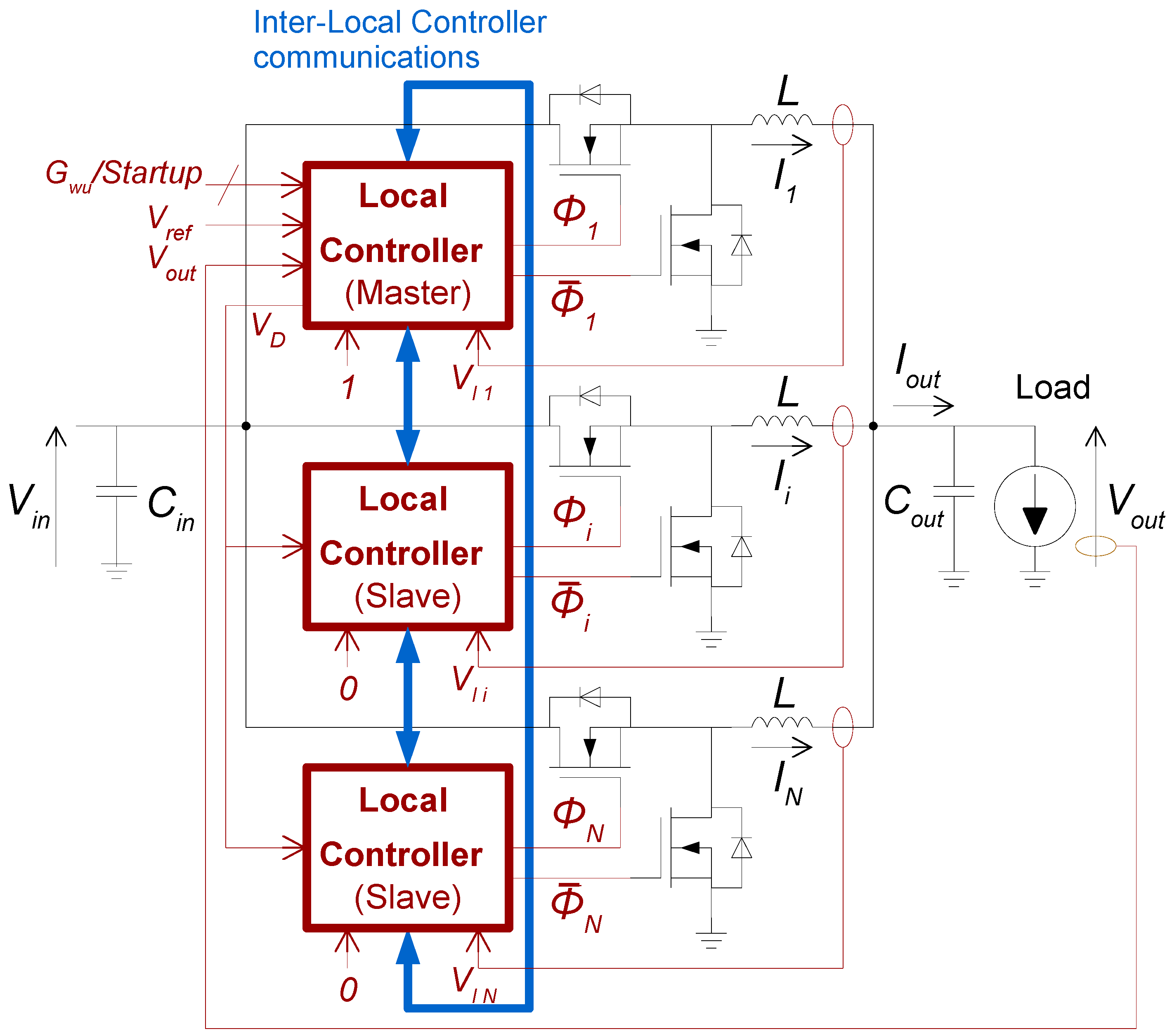
Figure 1 describes the decentralized/modular implementation of the phase-shedding technique for multiphase converters proposed in this article. It is based on a daisy-chain configuration of local phase controllers, each communicating only with its close neighbors. Each local controller monitors its own phase current, compares it with the minimum and maximum current thresholds, and locally decides to remain active or not depending on the state of its close neighbors. This control strategy effectively optimizes the output efficiency across the full load range, as presented in [
2], but in a decentralized manner.
In order to operate, the local controllers require several external signals provided either by a supervisor (startup/wakeup orders and the voltage reference Vref) or by sensors (phase currents Ii and the load voltage Vout). A Master/Slave bit determining their roles in the chain is also required. It should be noted that, in order to correctly operate during heavy-load events, such as the startup and wake-up of the load, as well as in reaction to a current inrush, the phase-shedding function has to be disabled automatically. Moreover, for very low load conditions, only one phase among the N will remain active and a so-called “low power” regulation mode will be used.
Figure 2 shows the several elements involved in the local controller. A current-mode voltage regulator is implemented. An error op-amp, activated only in the Master LC, equalizes the load voltage
Vout with the reference signal
Vref. It generates the signal
VD, which is compared to the output signal
VIi of the phase current sensor to produce the local PWM control signal. The signals
and
are generated, including a dead-time
DT. A state-machine, dedicated to implementing the phase-shedding function, manages the status of the LC, i.e., enabled or not, depending on the parameter values and behavior of external signals. To perform the appropriate control of a multiphase converter, decentralized PWM signal interleaving and phase current balancing functions are included in the system. For the sake of clarity and to focus only on the phase-shedding part, these functions are not detailed in the figure. All information about their implementation can be found in [
15,
20] for the interleaving and the current balancing, respectively. All details about the operation of the state-machine are provided in Chapter 2. It should be noted that the color code of Figs. 1 and 2 is respected in order to help in the understanding of the control system (the inter-LC communications are shown in blue; the other connections are shown in red).
In Chapter 2, the principle and architecture of the local controller are detailed. Its internal logic functions are described, along with the threshold and timing considerations necessary to configure the system and ensure optimal operation.
In Chapter 3, transient simulations show the appropriate phase-shedding behavior across the full load current range. Slow and fast load transients are considered and analyzed.
2. Principle
The principle of the presented control method is based on the usage of N identical local controllers, each associated with one phase of the multiphase converter. Each controller manages its own state (active or not) depending on the current level of its phase and the state of its close neighbors. Then, inter-controller communications are proposed using a daisy-chain topology, current thresholds are set, and timing considerations for the phase activation or deactivation delays are analyzed.
Moreover, it should be noted that, in order to handle some specific cases of operation (start-up, high load current, and low power control mode), one of the local controllers has to be set as the master, with the others being slaves. The roles can be permuted if necessary; for instance, to address fault tolerance purposes.
2.1. Daisy-Chain Architecture
First, each controller is assigned a status, either by an external supervisor or by hardware: one is the Master (M) and the others are Slaves (S). While M always remains ON, regardless of the load current, Slaves turn on or off in a chaser sequence according to the load current.
In order to achieve decentralization of the phase shedding, each S observes its own phase current and uses current thresholds to decide to stay ON or not. The goal is to maintain each active phase within its maximum local efficiency range, as shown in
Figure 3a. If the local phase inductor current increases and crosses
Imax, the number of active phases should increase, as shown in
Figure 3b; if it decreases and reaches
Imin, the number should decrease, as shown in
Figure 3c. This threshold crossing is monitored within each active local controller.
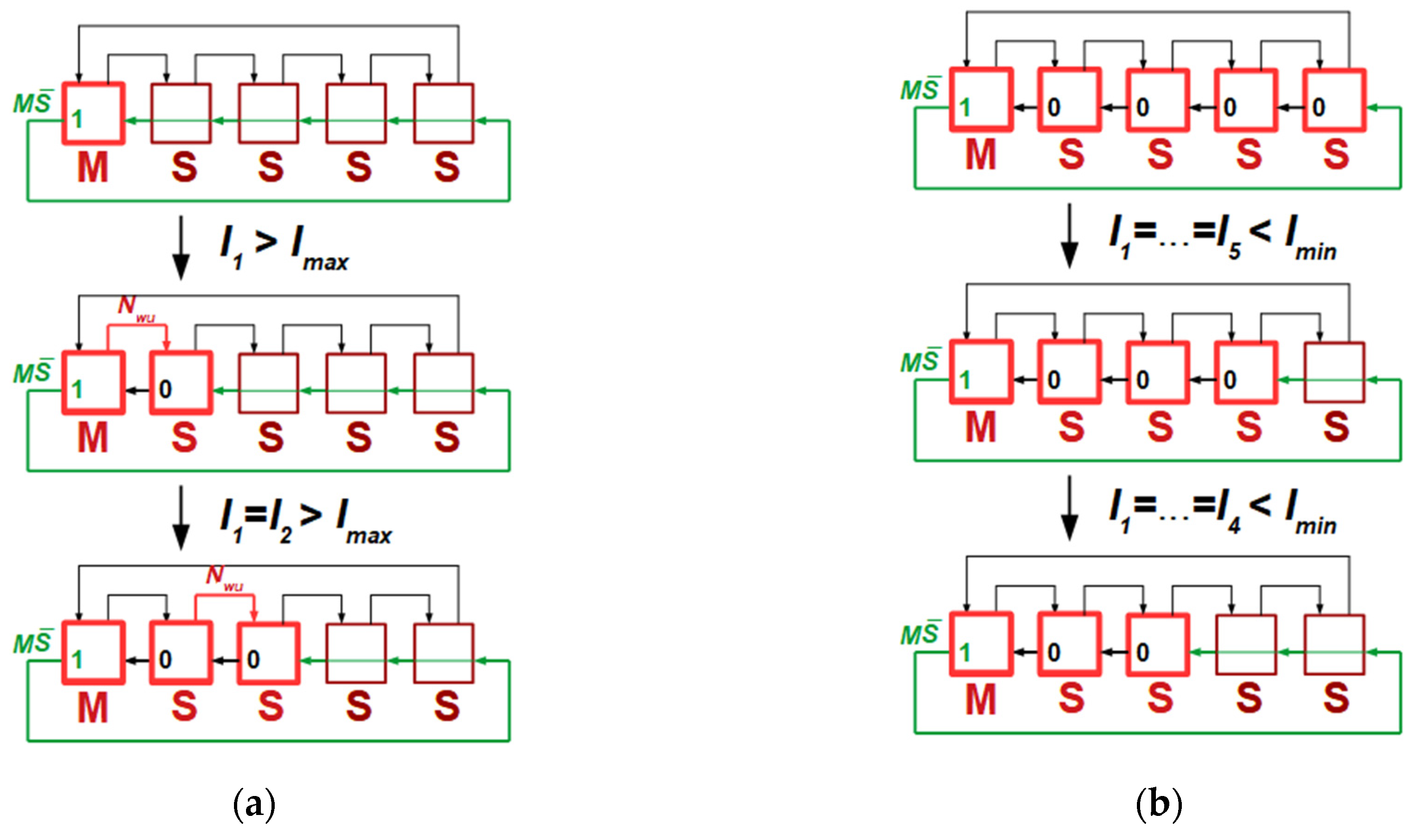
In the case of a current threshold being crossed and because all phase currents are supposed to be equal in steady state, a sequencing of the local controllers is required to prevent all of the phases from simultaneously turning on or off. This is achieved for the incremental turn-on sequencing by using a Master/NotSlave signal chain (
) received by the local controllers and sent in the opposite direction to their neighbors, as shown in
Figure 4. The master M sends
= 1 and this signal flows through every inactive phase, each one also sending
= 1 to their previous neighbor in the chain (they are called “bypassed”). The first active slave encountered by this signal can, therefore, acknowledge that it is leading the chain. It is allowed to use the current threshold crossings either to turn itself off (
Imin crossing) or turn its next neighbor on (
Imax crossing). From there, an active slave sends
= 0, indicating to active slaves not leading the chain that they cannot change their states. The signal scheme sets local controllers in an orderly manner within the chain, with only the leading one allowed to take action.
Phase activation and deactivation sequences are presented in
Figure 5. It is shown that if the low current threshold
Imin is crossed, the leading active Slave turns off and bypasses itself to indicate to the previous one that it has become the leading slave. On the other hand, if the high current threshold
Imax is crossed, the leading active Slave sends the Next Wake-up (
Nwu) signal to activate its next closest neighbor.
Two extreme cases can be highlighted: if all phases are already active, the number of active phases can only change by decreasing once Imin is crossed; if the Master is the only remaining active local controller and Imin is crossed, the Master goes into a Low-Power mode (LP), i.e., a voltage regulation mode based on a hysteretic control system such as Pulse Frequency Modulation (PFM) or Auto Pulse Skip Mode (APS), to maintain high efficiency even at lighter loads.
In addition to the standard operation of the system, which is based on the Imin and Imax current thresholds, specific events require all phases to become active at once: during system startup where a high output current is required to charge the output capacitor, during a heavy load activity already planned by the microprocessor, or during a heavy load current inrush. Two input bits, Startup and Global Wake-up (Gwu), allow the phase-shedding function to be disabled while activating all the Slaves, with the Master transmitting the Gwu signal to every Slave in a daisy-chain manner.
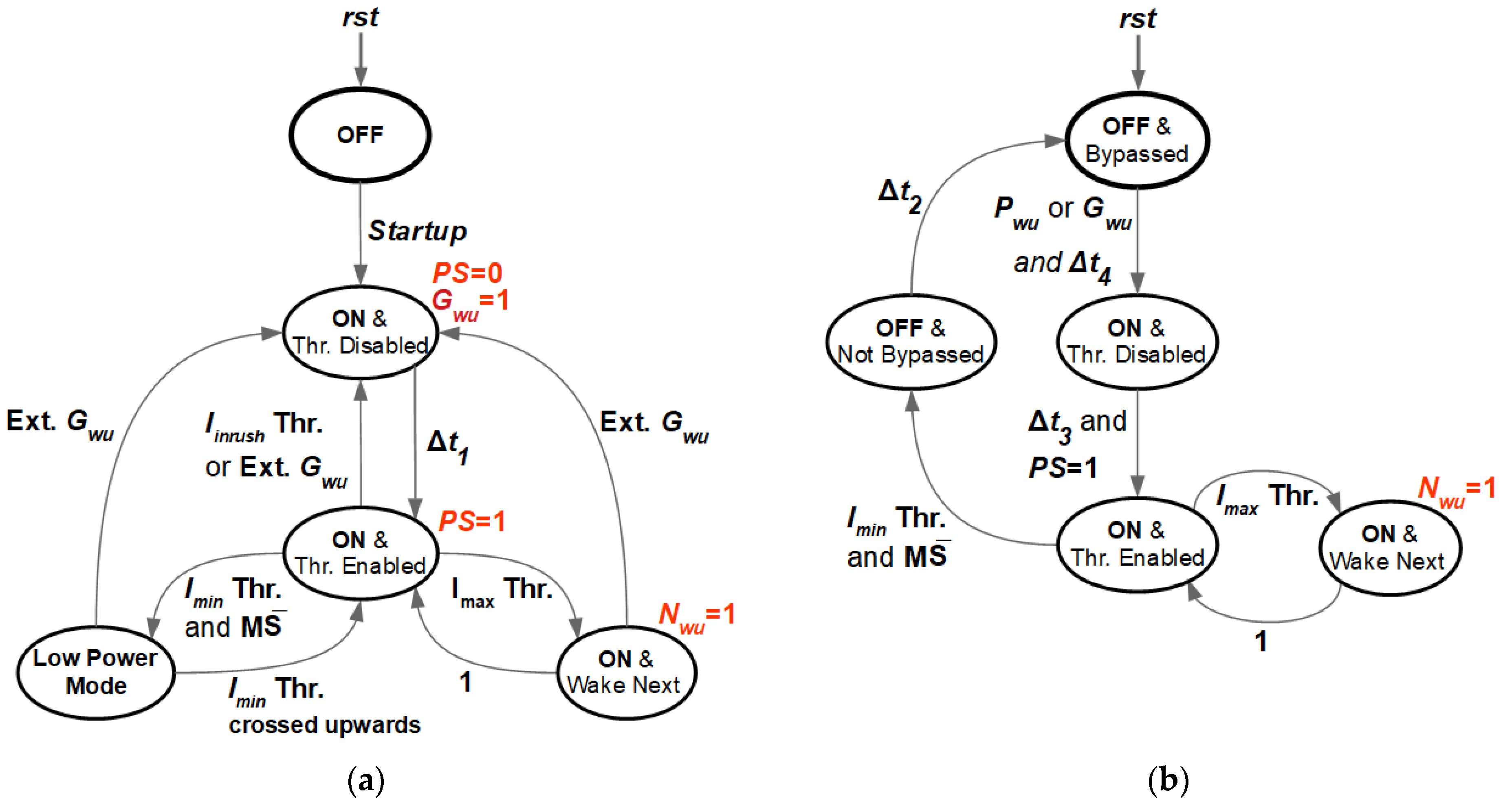
To implement this decentralized method, two state-machines are encoded in each local controller. Depending on the role played by the local controller, Master or Slave, the state-machine of
Figure 6a or
Figure 6b is used. It should be noted that, in the Master state-machine, the parameter
PS indicates whether the phase shedding is enabled or not.
However, in order to avoid instabilities during phase shedding, the principle of operation proposed requires additional considerations regarding the current threshold values and also the timing delays that are required during the activation/deactivation transitions.
2.2. Current Threshold Considerations
The previously described system, which is based on phase current monitoring and control logic units, does not guarantee the stability of phase shedding by itself. It is relevant to consider the stability issue during a deactivation sequence.
Indeed, one possible event is the decrease in the well-balanced phase currents of
k active phases all reaching the
Imin threshold at the same time (with
k ≤
N). Then, the leading Slave turns off and the inductor current of its phase discharges toward 0 A through the low-side power switch body-diode. If the load conditions do not change after this deactivation event, i.e., the load current
Iout remains equal to
kImin, a new steady state is reached where the remaining
k − 1 phases share the same portion of the load current. The
ith phase currents
Ii become:
where
k is the number of active phases among the
N phases of the converter.
Now, if the value of this local current exceeds the
Imax threshold, the upper threshold is crossed, and an order to reactivate the previously turned-off phase is sent by the leading Slave. Then, the currents of the now
k active phases will decrease again since no load event has occurred. This configuration is unstable. Hence, the condition to fulfill is the following:
The values of the steady-state phase currents depend on the number
k of active phases. A worst case for Equation (2) is obtained with
k = 2, i.e., the last remaining Slave turns off and
Imin is handled twice by the Master, resulting in the stability condition:
A second threshold consideration concerns the dynamic response of the phase-shedding system during an unexpected fast load current surge. As presented in the previous section, phases turn on sequentially during a current increase sequence, therefore limiting the transient response speed to a high inrush current event. The designed solution consists of implementing a third threshold higher than
Imax, called
Iinrush (see
Figure 3a).
This threshold is only considered by the Master and, as it is crossed, the Master issues a Gwu signal across the daisy-chain, temporarily turning on all phases and canceling the phase-shedding activity. The Iinrush threshold ensures the operational safety of the converter and leads to optimal efficiency during unforeseen strong load events.
2.3. Timing Considerations
Figure 6 shows transitions towards the “Wait for event” state, mainly current threshold crossing, which include delays Δ
t1, Δ
t2, Δ
t3 and Δ
t4. These delays must be implemented in order to create appropriate time shifts and to avoid instabilities.
Δt1: basic timing considerations concern the previously implemented Startup, Global Wake Up and Inrush events.
On the one hand, the duration of the Startup event, during which phase shedding remains deactivated, depends on the application and has to be estimated considering the time required to charge the output capacitor.
The duration of both the Gwu and Iinrush events, which are induced by external actions, has also to be designed according to load specifications and worst-case current surge transients.
Δt2: on the other hand, the increase and decrease rate of the local inductor current has an impact on the duration of transients during phase-shedding transitions.
Upon deactivation of a phase, the local inductor current decreases, over time, from Imin to 0 A. During this transient stage, the remaining active phases see their local currents increase while still potentially remaining below Imin. If the deactivated phase is bypassed too quickly and sets its previous neighbor as the leader of the chain, the latter would potentially deactivate itself as well. A chain reaction occurs, leading to a fast deactivation of all Slave phases.
To prevent this chain reaction, a delay between the phase deactivation and its bypassing is implemented. Its value corresponds to a full inductor discharge transient, and can be computed using simple design and application considerations:
where
Rph is the ohmic resistive path of each phase (
RON switches + inductor DCR + copper wires), and
τ is the time constant
L/
Rph.
Unless the load current decreases further, which would create a valid sequential deactivation of phases, such a delay ensures that all remaining phases have time to cross the Imin threshold in an upwards direction before the leading one is allowed to deactivate itself.
Δt3: the activation of a phase is another potential source of instability. During the inductor charge transient of an activated phase from 0 A to Iout/k, as the local controller sees its local current below the Imin threshold, it will try to turn itself off.
A delay implemented between the moment of phase activation and the one when the phase is allowed to deactivate itself solves this instability issue. The worst case to consider is a phase current after charging in steady state right above the
Imin threshold, i.e., the load current slightly higher than
kImin. Hence, full charge has to be reached before deactivation is allowed:
This delay allows 99% of the steady-state current value to be reached before any further transition.
Δ
t4: the last delay consideration corresponds to the prevention of a re-wake event due to the large bandwidth voltage regulation loop. After a phase is deactivated, during a short transient stage, the voltage regulation loop might cause a temporary increase in the duty-cycle, inducing a local current overshoot across the remaining active phases. The phase current of the new leading Slave may, in turn, potentially cross the
Imax threshold and cause it to send a
Nwu signal to wake up the phase that has just been deactivated. To prevent this behavior, a delay has to be added between the deactivation of a phase and its ability to be reactivated, as shown in
Figure 6b.
3. Simulation Results
This section presents the simulation results of the multiphase converter controlled by the proposed decentralized phase-shedding technique.
Table 1 shows the parameters of the application, which requires a five-phase multiphase buck converter.
The voltage loop error amplifier is only active in the Master. Its output is connected to the node COMP in order to send the signal that allows computation of the local PWM signals to all remaining Slave Local Controllers [
19].
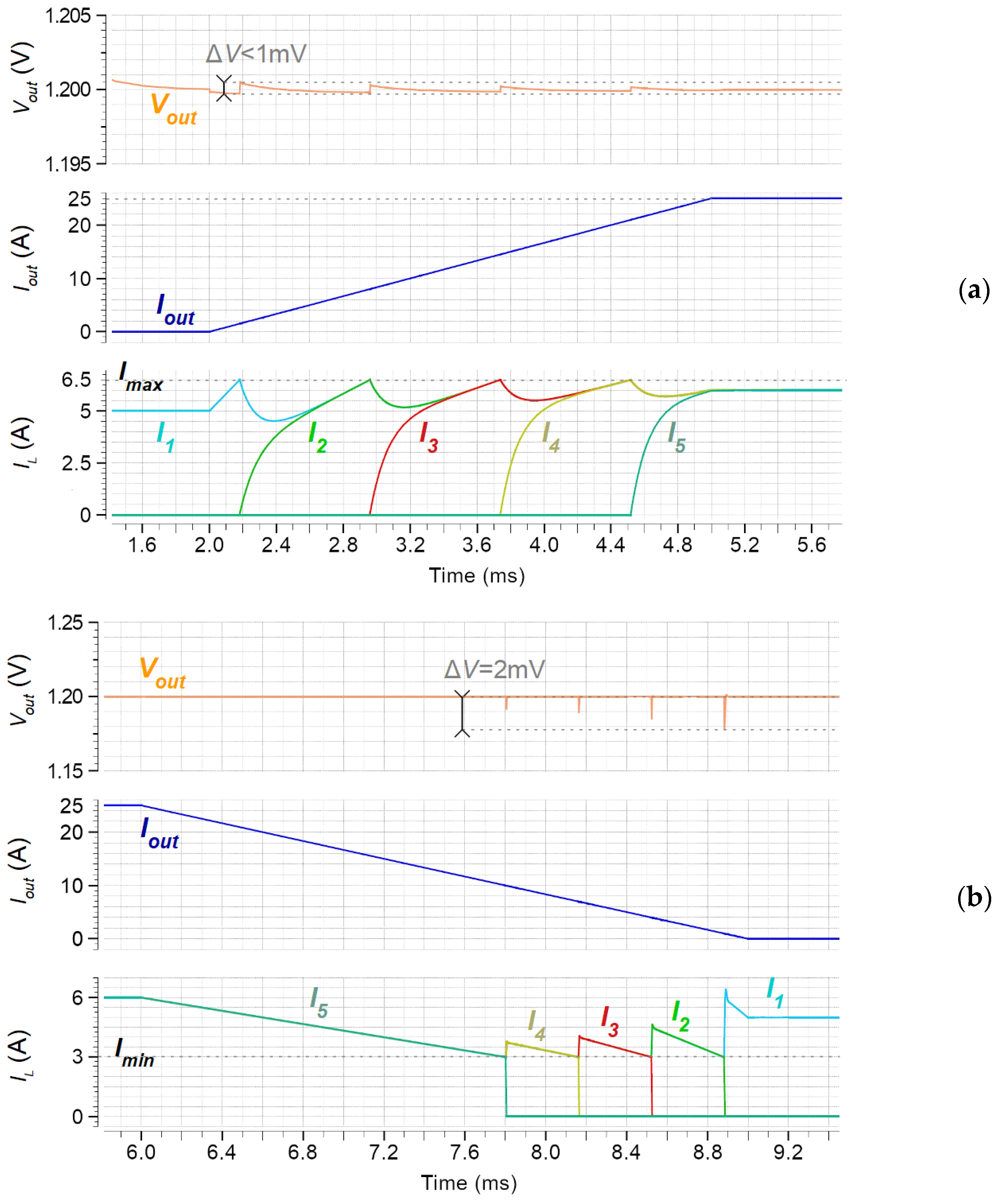
The simulated load scenarios feature output current transients covering the converter’s entire current range, thus showing phase shedding during both a turn-on and a turn-off sequence (
Figure 7).
An appropriate phase-shedding scheme is obtained in both cases with a smooth sequence set by
Imax and
Imin, as well as delays Δ
t3 and Δ
t4.
Figure 7a shows the system response to a slow increase in the load current. Each time a phase’s local current reaches
Imax = 6.5 A, a local wake-up signal is sent to the next phase by the leading Slave, thus increasing the number of active phases. The opposite behavior is observed in
Figure 7b, where phases are successively deactivated each time
Imin = 3 A is reached.
A secondary simulated scenario, shown in
Figure 8, is the fast decrease in the load current. Delay Δ
t2 prevents a deactivation runaway during a fast decreasing load transient. Each phase sees its local current decrease below
Imin, but this delay ensures a smooth transition from five phases to one phase by time-shifting the ability of a phase to turn itself off when it leads the chain.
Finally, the effect of the third threshold
Inrush used to handle a fast inrush current transient is illustrated in
Figure 9. The natural incremental phase-shedding response to a strong inrush current, i.e., without threshold
Inrush, is presented in
Figure 9a. A potentially destructive 13 A overcurrent is observed in one phase and the system time response is 6 ms. In
Figure 9b, the threshold
Inrush is used. It generates a global wake-up signal
Gwu that activates all phases instantaneously, overriding the phase-shedding function. The system transient is improved with only a 2 ms time response and a lower safe overcurrent is reached with only 8 A for the Master.
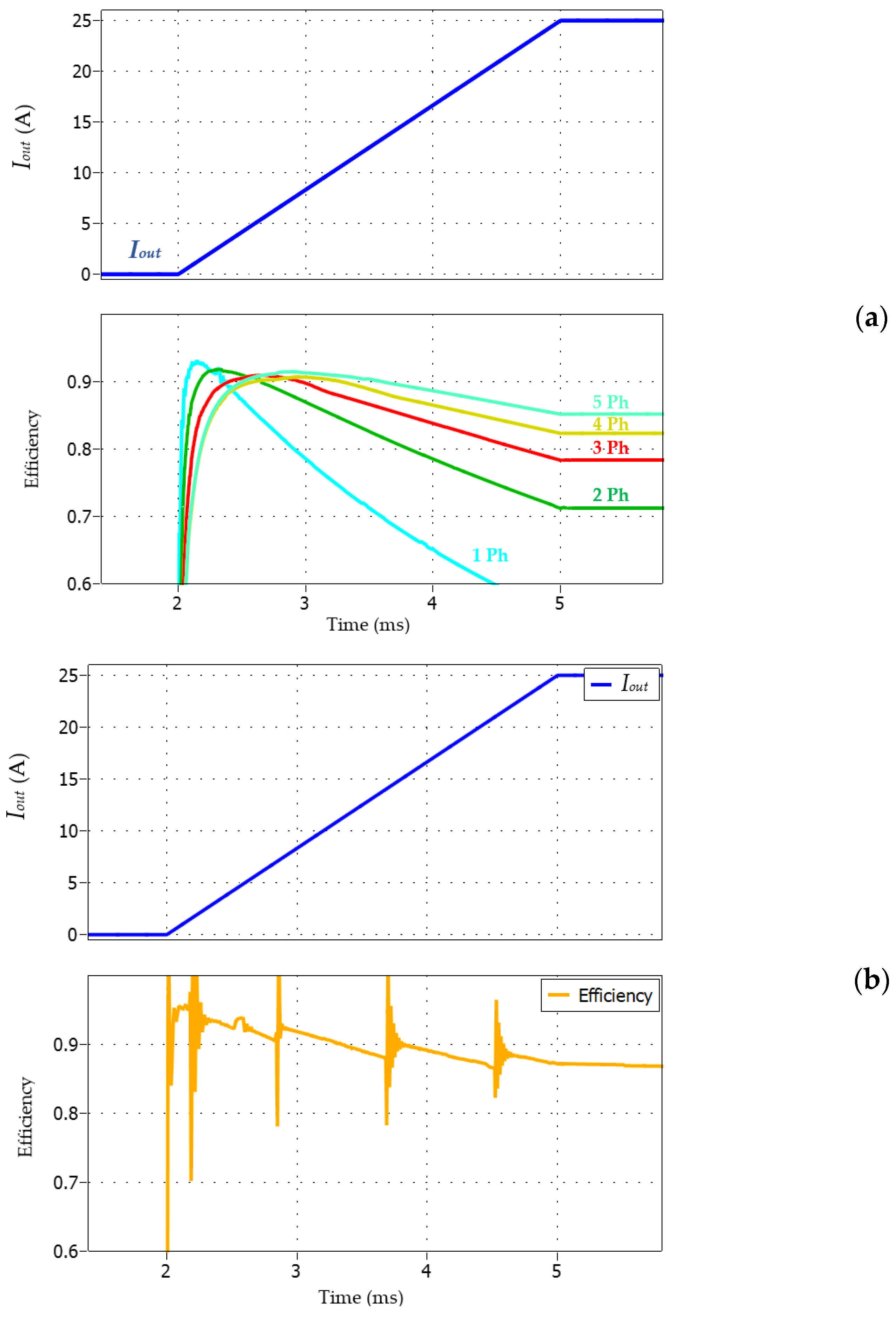
Figure 10 shows the simulation results for the power efficiency of the multiphase converter. Accurate models of 25 V/51 A 6 mΩ power MOSFET transistors are considered, as well as parasitic components (the ohmic path of the wire, the inductive effect, and the inter-wire capacitor).
Figure 10a presents the power efficiency characteristics, which are dependent on the number of active phases when no phase shedding is considered. One can observe that the efficiency drastically decreases if only one phase is used. On the other hand, the higher the number of phases, the better the efficiency at high load current. However, the maximum efficiency level is shifted toward the right, as predicted by the theory.
Figure 10b shows the behavior of the global efficiency of the converter when using the phase shedding for an increase in the load current. The phase sequence is similar to the one shown in
Figure 7a. One can observe the efficiency waveform jump from one characteristic to the other when enabling the phases, then remaining in a tight range from 0.85 to 0.95.
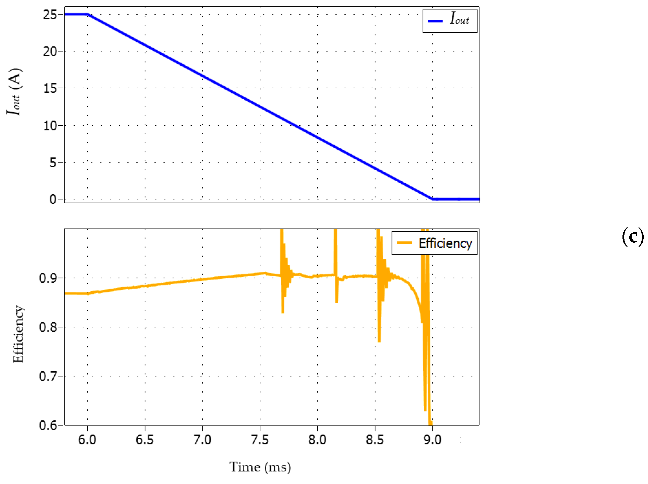
Figure 10c presents the same simulation but with a decreasing load current. Again, the phase disabling sequence, similar to the one in
Figure 7b, allows the power efficiency to be limited in a tight range from 0.8 to 0.9. It should be noted that, first, high-frequency oscillations are mainly due to calculation approximations during transients, and second, because the low power mode at low current level is not simulated, the value at zero current level should not be considered.
5. Conclusions
A decentralized phase-shedding technique is presented. If the phase-shedding function dedicated to maximizing the power efficiency, in a manner that is dependent on the load current, is provided by a centralized controller, a Single Point of Failure is obtained in the system, meaning that it is not fault-tolerant. Thanks to this study, a decentralized control approach to implement this function by removing any SPOF has been established.
The decentralized control method consists of turning on or off a phase of the multiphase converter based on local decisions. Each phase monitors its own local current and compares it with the minimum and maximum predefined thresholds. Using local communications, depending on its own position in the chain and the state of the others, each phase consequently disables or enables its local power stage. For very low load currents, only one phase remains active. It then goes into low power mode to maximize the converter efficiency accordingly. In order to handle specific events such as a start-up sequence or inrush current requiring the fast activation of all the phases, additional functionalities are included in the local controllers. The protocol used to communicate between the cells is described, along with necessary design considerations of threshold and time shifting values.
Functional simulations are carried out on a 5-phase 12 V/1.2 V 60 W multiphase converter dedicated to supplying a microprocessor. It is observed that the number of active phases is well adjusted, in a dynamic manner, depending on the load current level, as expected. Specific events such as load current inrush or a start-up sequence are also simulated and show optimal transient responses.
Thus, the phase-shedding function is achieved using identical local controllers, making it possible to dispense with a central controller. It can be concluded that, first, using this decentralized control method, the number of phases that can be handled is not limited, and second, if the master status can be shared on a rotational basis, any SPOF is removed.


 ,
, 


