Abstract
Shunt active power filters (APFs) are used to address power quality issues such as harmonic distortion and power system imbalance. Many control systems for shunt APFs demand measurements of voltages and currents for the determination of instantaneous real and reactive power signals. From these signals, the reference currents of the shunt APF are calculated. A method of control for the APF shunt that only measures currents is proposed in this paper. The control method includes a modified technique to extract the positive and negative sequence components in the time domain. The reference currents in the shunt APF are calculated by the negative sequence components of the measured currents. Simulation and experimental results confirm the efficiency of this control scheme under ideal and non-ideal conditions.
1. Introduction
Shunt APFs have been utilized to improve power quality of a power system [1]. In recent decades, sensorless grid-voltage control has been an interesting topic for research [2]. Voltage-sensorless control for voltage-sourced inverters (VSIs) has been studied for several years for reducing system costs and potentially improving system reliability [3]. Measurements of both voltages and currents are required by traditional active power filter (APF) control techniques [4,5]. Therefore, the system is always configured with both a voltage and a current sensor. Accurate voltage information is crucial to the efficiency of the APF [6]. Some approaches, such as the synchronous reference (SRF) system and the instantaneous reactive power theory (IRPT), need the voltage magnitude and phase to evaluate the correct reference signals for the inverter in the APF.
Sensor failure and faults have a significant impact on the performance of the shunt APF [7]. They can cause the shunt APF to fail, which exacerbates harmonics in the power system rather than reduce them. Due to various technical and economic considerations, sensorless and fault tolerant operation of the shunt APF is strongly desired. It is possible to eliminate a number of sensors to implement sensorless control systems [5]. Replacement of AC voltage sensors with estimation is a reasonable choice, as it eliminates sensor offset, resolution limitations and noise. In addition, it enhances robustness against sensor failures, improves the system reliability and lowers the system costs [2,6]. Because the grid voltage is not sensed directly through sensors or a phase-locked loop (PLL) in sensorless control techniques, it can be estimated from other measured quantities such as the currents and the DC-link voltage [8]. These quantities are important for controlling the inverter in the APF and for protecting from short circuit and over-and-under voltage conditions [4]. Sensorless control could also enhance the efficiency of a converter in the production of renewable energy, because failure of the measuring sensors, cables or interfaces does not automatically mean the end of operation [2]. In the case of grid-voltage sensorless control, unbalanced conditions can also be addressed. To ensure reliable control and low current harmonics, voltages should be clear of significant distortion [9]. Under voltage distortion, notching or line-frequency variations, line synchronization cannot be properly controlled. It is, therefore, very important to regulate the active power filter without sensing the voltage.
Several sensorless control techniques have been suggested [2,3,4,5,6,7,8,9,10,11,12,13,14,15]. Some estimation approaches have been proposed to replace some of the measurement sensors with software algorithms. Such algorithms are used to approximate instantaneous values of the desired amounts by the system parameters and other measurable quantities [10]. The two common voltage-sensorless control strategies are generally the voltage-oriented control and the current shaping control [4]. Voltage-oriented control shows poor performance due to modeling errors. The current shaping control is simple and performs more stable and robustly. The system condition of the point-of-common coupling (PCC) under unbalanced voltages was not considered in some techniques. However, other techniques involve a voltage unbalance. An enhanced adaptive observer for grid-voltage sensorless control is used under extremely unbalanced conditions to estimate the positive- and negative-sequence components of the grid voltage [2]. A method of voltage sensorless multi-loop control is proposed for single-phase UPS inverters using two variables as feedback signals that regulate with simple proportional controllers rather than PI/PR controllers [10]. In addition, a voltage sensorless current control system utilizing an adaptive estimator for unknown dynamics in the deadbeat control scheme was suggested in [11]. In [9], a method of sensorless voltage control using indirect synchronization was proposed. Another voltage sensorless control technique was performed by the virtual resistance emulation method based on an open loop approach [3]. Nevertheless, it depends on the accuracy of the plant model. For the islanding condition, a sensorless voltage method is used, utilizing resonant integrators for harmonic grid-voltage estimations [12]. Furthermore, the voltage-sensorless direct power control with virtual flux estimation technique is commonly implemented for induction motors [13,14]. In [15], the phase angle of the source voltage was estimated by using the control error in the current controller. Some other techniques utilized the line current and its derivatives for tracking the system frequency in order to calculate the voltage.
In [1], a voltage sensorless control strategy for a shunt APF operating in an unbalanced system was proposed. This method did not detect the grid voltage and did not use estimation techniques for the voltage. Only current sensors for load and filter currents were utilized. The reference currents were generated using a proposed extraction method for positive and negative sequence components. Typical control schemes for shunt APFs utilize voltage and current measurements in the abc frame of reference, which are transformed into other reference frames to determine an instantaneous power signal. Current references are calculated in this new reference frame and then transformed back to the abc reference frame to generate the inverter gate drive signals. In the proposed control method, only current measurements are necessary to produce the inverter gate drive signals. No change in reference frame is needed, because the determination of the inverter current commands is performed in the abc reference frame. In addition, the proposed method eliminated the need for extra elements such as low-pass and high-pass filters or a phase-locked loop. Other techniques for extracting the positive and negative sequence components of system voltages and currents have been described in the literature [16,17]. Typically, these require that the voltages and currents be transformed from the abc frame of reference to another reference frame. Demonstrated in this paper is the control of a shunt APF for unbalanced conditions using only current measurements—no voltage measurements are needed. In addition, the sequence components of the measured load currents are determined in the time domain and in the abc frame of reference. No coordinate transformations are utilized in calculating the sequence components. A more detailed evaluation of the performance of this control strategy is presented in this paper.
2. Description of Shunt APF Model
As shown in the Figure 1, the system under study is a three-phase three-wire system, which comprises a three-phase AC voltage source, grid impedance, a line impedance, several sets of loads and shunt APF consisting of a passive LCL filter and a VSI fed by a DC power supply. The LCL filter links the shunt APF to the grid. A set of loads, including a non-linear (NL), balanced linear load (BLL) and unbalanced linear load (ULL), connected to the supply through the line impedance. The following can be measured: voltages at the point-of-common coupling (PCC), load current (iL) and filter current (if), as depicted in Figure 1. However, in the proposed control scheme, only the load and filter currents are measured.

Figure 1.
Shunt active power filter (APF) connected to the power system.
Under ideal and non-ideal power system conditions, the shunt APF is built to maintain balanced sinusoidal three-phase source currents (is). Load currents () consist of fundamental components (), harmonic components () and reactive components () and are expressed as:
The shunt APF injects currents of equal magnitudes as the harmonic and reactive components of the load currents as following:
As a result, the unwanted components are then extracted from the source components by:
3. Proposed Control System
The proposed control technique using only current measurements is based on separating the negative sequence components and higher harmonics of the positive sequence components from the measured load currents. The approach used to remove these components is based on the correlation between the time delay and the phase difference. The time delay referring to the phase difference between phases for two consecutive phases is determined as:
where tc is the period of a cycle. The transformation of symmetrical components is used for the separation of positive sequence and negative sequence components.
From the traditional symmetrical component transformation, the recognizable operator is . Using (4), a −240° phase shift is equivalent to a time delay of 1/90 s [(−240/360)/60] for a 60 Hz system. Similarly, the operator is equivalent to a time delay of 1/180 s [(−120/360)/60] for a 60 Hz system. The proposed sequence component detection approach utilizes symmetrical time-domain components, as seen in (6). These equations employ α and α2 where the time delay corresponding to α is 1/90 s, and the time delay corresponding to α2 is 1/180 s. The transformation of symmetrical time-domain components can be formulated to derive positive and negative sequence components from three-phase quantities fa(t), fb(t) and fc(t).
The quantities of abc phases can be determined from the symmetrical components of the time domain as follows:
From Equation (7), the positive sequence components are determined as:
The negative sequence quantities are also determined from Equation (7) as:
It can be noted from Equations (8) and (9) that the quantities are balanced three-phase with fixed magnitudes and phase differences of 120°. Since the system in Figure 1 is ungrounded, the zero sequence current components are zero. Therefore, negative sequence components and higher harmonics of the positive sequence components of the load currents can be calculated, as shown in Figure 2. The positive sequence component of the load is calculated as 1/3(ILa + αILb + α2ILc) from (6). The proposed control system was implemented using a dSpace system, which contains a time delay block that was employed in the implementation here. In the presence of harmonic voltages and currents, a harmonic filter is used with the separation method to generate the current components at the fundamental frequency of the system. The summation on the right-hand side of Figure 2 creates the positive sequence fundamental components of the load current using (8).

Figure 2.
Block diagram of the proposed current reference algorithm.
After the positive sequence components of the load currents are determined, they are subtracted from the load current to yield the negative sequence components (, , ) and higher harmonics of the positive sequence components (, , ) of the load currents. The reference currents for the inverter are calculated as follows:
To produce the switching signals for the inverter, these reference signals are then compared with the measured filter (inverter) currents. This approach involves no transformation of the measured signals and has lower complexity. Figure 3 illustrates the generation of the switching signals for the VSI. Note that the current references generated by (10) are compared to the measured filter currents. The pulse width modulation PWM block in this figure was implemented with a PWM generator from MathWorks [18]. The AC compared signals are scaled by a gain to maintain the magnitude of the compared signal within the range of −1 to +1 to ensure linear operation of the PWM block.

Figure 3.
Generation of the inverter gate drive signals.
4. Performance Evaluation
Performance of the proposed extraction method and the proposed control method based only on current measurements was evaluated through both simulation and hardware experimentation.
- 1.
- Validation of the Proposed Extraction Method
The method to extract the sequence components from system variables was evaluated in both simulation and experiment. The system under test consists of a three-phase voltage source, simulated grid impedances, a measurement board and three resistive loads of 5 Ω each. With a resistive load, the currents are simply scaled versions of the voltage waveforms. Measurements of the voltages at the PCC were obtained, and the extraction method was implemented on a dSpace DS1104 R&D controller card and CP 1104 I/O to determine the positive sequence components. The evaluation was performed in two test cases: (1) balanced voltages and (2) unbalanced magnitudes and phase angles.
- Balanced three-phase quantities:
Balanced voltages were applied to the system, the voltages at the PCC were acquired, and the positive sequence components of the PCC voltages were extracted. As can be seen in the simulation results in Figure 4a, the extracted voltages match the PCC voltages as expected. The experimental results in Figure 4b show that the extraction method was able to determine the positive sequence voltages as well.

Figure 4.
For balanced conditions: (a) simulation and (b) experimental evaluation of the proposed extraction method where measured point-of-common coupling (PCC) voltages at the top and the positive sequence components of PCC voltages at the bottom.
- Unbalanced magnitudes and phases:
Next, the magnitudes of the grid voltages are to set 12 V, 11 V and 15 V, and phase displacement between phases A and B is 210° and between phases A and C is 100°. The proposed extraction method was able to determine the positive components of the PCC voltages in the unbalanced case, as shown in Figure 5.

Figure 5.
For unbalanced conditions: (a) simulation and (b) experimental evaluation of the proposed extraction method where measured PCC voltages at the top and the positive sequence components of PCC voltages at the bottom.
Based on the results in these two cases, the proposed method was able to extract the positive sequence components for both balanced voltages and unbalanced voltages. The experimental results validated the operation of the proposed method even in the presence of noise in the PCC voltages.
- 2.
- Evaluation of the proposed control method
A number of evaluations was conducted under several load and source conditions even in the presence of the harmonics. The efficacy of the control method was based on the reduction percentage in the total harmonic distortion (THD) and the amplitudes of the source currents. Results for three-phase balanced and unbalanced grid voltages and three different load conditions included: a nonlinear load (NL) using a rectifier and a resistive load, a linear balanced load (BLL) and an unbalanced linear load (ULL).
MATLAB/Simulink software was used to build and simulate the system. The results were taken via Simulink scopes and FFT analysis tool. The laboratory setup shown in Figure 6 comprised an NH Research NHR 9410 grid simulator, a HiRel power electronics drive board, a DSP-based dSpace DS1104 R&D controller board and CP 1104 I/O, a DC power source, MATLAB Simulink and dSpace control desk and current measurement boards. The control system uses only measurements of ILa and ILb; therefore, ILc is calculated based on the formula ILa + ILb + ILc = 0. For that reason, there is an increase in the magnitudes of source currents coming from the APF currents. In addition, ideal components are assumed in the simulation. However, non-ideal components are utilized in the laboratory. A Tektronix MIDO 3024 oscilloscope was used to display all output waveforms. Line-to-line voltage at the PCC (Vab-pcc) and the source currents for phase a (Isa) and phase b (Isb) were recorded and plotted. Table 1 presents the parameters of the system.

Figure 6.
Experimental setup of the system.

Table 1.
System parameters.
- Simulation results
Case1: Balanced grid voltages:
This first simulation case evaluated the system with balanced source voltages with a nonlinear load and then an unbalanced load. Presented in Table 2 is the THD of the source currents with and without the shunt APF for the two loads. The THD of the source current is reduced sharply for the NL. For the BLL and ULL, the THD of the source current was low, but it increased slightly due to switching harmonics from the inverter. The magnitude of the source currents with and without the shunt APF are shown in Table 3. For the BLL and NL, the current magnitudes remained balanced but increased slightly. Note that the shunt APF is able to balance the current magnitudes for the ULL. Shown in Figure 7a are the PCC voltages, the source currents, the load currents, and the filter currents. Note that the source currents are balanced and sinusoidal even with the distorted load currents. In Figure 7b,c, it can be seen that the source currents are balanced for both the balanced and unbalanced loads.
Table 2.
THD of the source currents (Is) without and with the shunt APF.
Table 3.
The magnitudes of Is without and with the shunt APF.
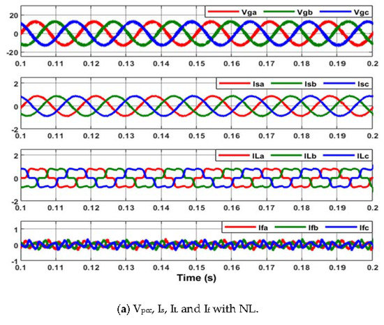

Figure 7.
Source current (Is), load current (IL) and filter current (If) with the shunt APF when the source voltages are balanced.(a) VPCC, Is, IL and If with NL (b) Is, IL and If with BLL. (c) Is, IL and If with ULL.
Case 2: Unbalanced grid voltages:
Phase A, B and C grid voltages were set as 10.5∠0° Vrms, 11.5∠−110° Vrms, 13.5∠110° Vrms, respectively. As given in Table 4, the THD of the source current was highly reduced with NL. The THD under BLL and ULL was low; however, there was a slight increase due to the switching harmonics from the inverter gates. Table 5 and Figure 8 demonstrate that the source currents were balanced and sinusoidal waveforms under different types of loads.
Table 4.
THD of Is without and with the shunt APF.
Table 5.
The magnitudes of Is without and with the shunt APF.
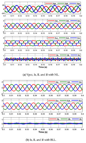

Figure 8.
Is, IL and If with the shunt APF when the source voltages are unbalanced. (a) VPCC, Is, IL and If with NL (b) Is, IL and If with BLL. (c) Is, IL and If with ULL.
- Experimental results
Case 1: Balanced grid voltages:
(A) NL
The shunt APF was able to eliminate the harmonics in the source current to obtain sinusoidal signals when NL was applied, as shown in Figure 9. Figure 9a displays the PCC voltage and source currents without the shunt APF. The shunt APF eliminated the harmonics resulting in sinusoidal source currents, as seen in Figure 9b. The THD of the source current decreased dramatically from 24.6 to 5.1%, as seen in Table 6. The THD measurement was obtained by the Tektronix Oscilloscope. The current magnitudes increased marginally, because the experimental control scheme used only ILa and ILb measurements; thus, ILc is determined on the basis of ILa + ILb + ILc = 0. There is, however, a small rise in the amplitude of the source currents.
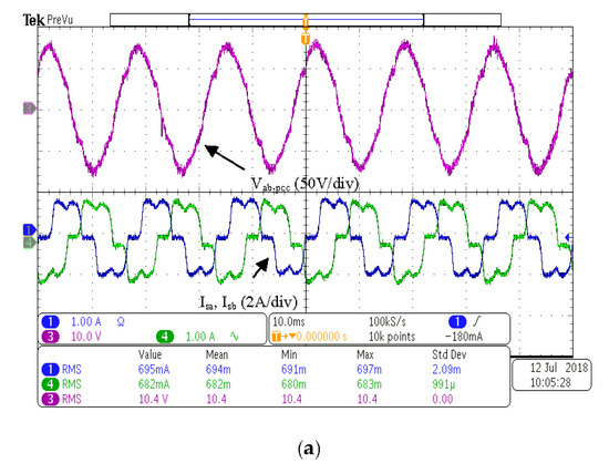

Figure 9.
(a) vab-pcc, isa and isb without the shunt APF. (b) vab-pcc, isa and isb with the shunt APF. (10 ms/div).
Table 6.
Magnitudes and THD of the source currents.
(B) BLL
For the balanced load, the shunt APF did not distort the voltage or currents as presented in Figure 10. The THD was reduced slightly as seen in Table 7. The source currents were still balanced, but the magnitude increased.
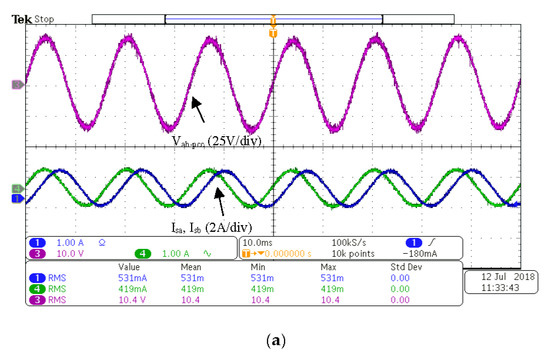

Figure 10.
(a) vab-pcc, isa and isb without the shunt APF. (b) vab-pcc, isa and isb with the shunt APF. (10 ms/div).
Table 7.
Magnitudes and THD of the source currents.
(C) ULL
As shown in Table 8, the shunt APF was able to balance the magnitudes of the source currents with the unbalanced load. The THD of the source current was low, yet due to switching harmonics from the inverter, it increased marginally. Sinusoidal and balanced source currents were obtained with the shunt APF, as depicted in Figure 11.
Table 8.
Magnitudes and THD of the source currents.
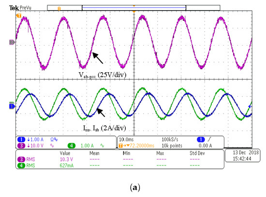

Figure 11.
(a) vab-pcc, isa and isb without the filter. (b) vab-pcc, isa, isb and ifb with the filter. (10 ms/div).
Case 2: Unbalanced magnitudes and phases of the grid voltages
(A) NL
Under NL conditions, the THD of source currents decreased from 26 to 5.1%, as seen in Table 9. The magnitude of the source currents was also balanced. Therefore, the source currents were sinusoidal with approximately the same amplitude as presented in Figure 12b.
Table 9.
Magnitudes and THD of the source currents.
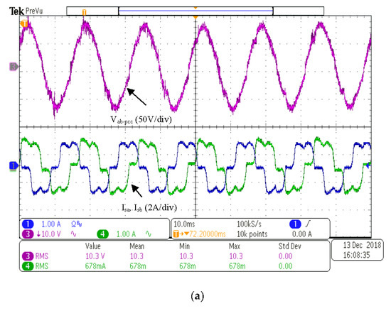

Figure 12.
(a) vab-pcc, isa and isb without the filter. (b) vab-pcc, isa and isb with the filter. (10 ms/div).
(B) BLL
With unbalanced voltages and a balanced load, the shunt APF was able to balance the source currents shown in Figure 13b. The current magnitudes in Table 10 are identical as measured by the oscilloscope. Additionally, the THD was maintained within the satisfactory range.
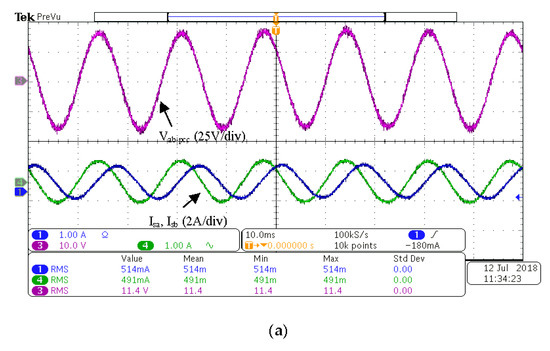

Figure 13.
(a) vab-pcc, isa and isb without the shunt APF. (b) vab-pcc, isa and isb with the shunt APF. (10 ms/div).
Table 10.
Magnitudes and THD of the source currents.
(C) ULL
ULL was connected and unbalanced voltages were applied to the system. Table 11 indicates that the magnitudes of the source currents were nearly the same relative to the magnitudes without the APF shunt. When the shunt APF was functioning, the THD of the source current remained low. Figure 14 indicates that the source currents were sinusoidal with approximately identical amplitudes.
Table 11.
Magnitudes and THD of the source currents.

Figure 14.
(a) vab-pcc, isa and isb without the filter. (b) vab-pcc, isa, isb and ifb with the filter. (10 ms/div).
In brief, the efficacy of the proposed control scheme for the shunt APF has been shown in both simulation and experimental findings. The source currents in all evaluation cases were balanced and sinusoidal. Moreover, the THD amounts for the source currents comply within acceptable limits [19]. When the load was nonlinear, harmonics at the PCC voltages were also reduced.
5. Conclusions
Proposed in this paper is a control system for a shunt active power filter for ideal and non-ideal power system conditions including harmonics. Typical control systems for shunt APFs utilize either measurement or estimation of a power system voltage. This voltage information along with current measurements is utilized to calculate an instantaneous power signal from which the inverter gate drive signals are derived. In the control system proposed in this paper, the inverter gate drive signals are derived from current measurements only. No voltage measurements are needed, which is an advantage over other control methods for shunt APFs. The load currents are measured, and their positive and negative sequence components are extracted using a time domain symmetrical component transformation. These components are the reference currents for the current controller in the shunt APF inverter to produce the inverter gate drive signals. Because the sequence components of the currents are determined in the time domain in the abc reference frame, the computational requirements of the proposed control scheme are reduced compared to other control schemes for shunt APFs. In addition, the elimination of the calculation of any power signals for the proposed control scheme further reduces computational requirements. Simulations and experimental results have illustrated that the proposed control system guarantees balanced sinusoidal source currents under many power system conditions. Furthermore, the control system can reduce the THD of the source currents to an acceptable limit in the presence of a highly distorted load current.
Author Contributions
Conceptualization, S.F.A.-G. and R.M.N.; Formal analysis, S.F.A.-G.; Investigation, S.F.A.-G.; Methodology, S.F.A.-G.; Supervision, R.M.N.; Validation, R.M.N. All authors have read and agreed to the published version of the manuscript.
Funding
This research received no external funding.
Conflicts of Interest
The authors declare no conflict of interest.
References
- Al-Gahtani, S.; Nelms, R.M. A New Voltage Sensorless Control Method for a Shunt Active Power Filter for Unbalanced Conditions. In Proceedings of the 2019 IEEE International Conference on Environment and Electrical Engineering and 2019 IEEE Industrial and Commercial Power Systems Europe (EEEIC/I&CPS Europe), Genova, Italy, 11–14 June 2019; pp. 1–6. [Google Scholar]
- Kukkola, J.; Hinkkanen, M. State Observer for Grid-Voltage Sensorless Control of a Converter Under Unbalanced Conditions. IEEE Trans. Ind. Appl. 2018, 54, 286–297. [Google Scholar] [CrossRef]
- Bai, H.; Blaabjerg, X.W.F. A Grid-Voltage-Sensorless Resistive-Active Power Filter with Series LC-Filter. IEEE Trans. Power Electron. 2018, 33, 4429–4440. [Google Scholar] [CrossRef]
- Kennel, R.; Szczupak, P.; Boller, T. Sensorless Control of 3-Phase PWM Rectifier in Case of Grid Phase Disconnection. In Proceedings of the 2005 IEEE 36th Power Electronics Specialists Conference, Recife, Brazil, 12–16 June 2005; pp. 2019–2022. [Google Scholar]
- Ketzer, M.B.; Jacobina, C.B. Sensorless PWM rectifiers with active filter action. In Proceedings of the 2015 IEEE 24th International Symposium on Industrial Electronics (ISIE), Buzios, Brazil, 3–5 June 2015; pp. 405–410. [Google Scholar]
- Wojciechowski, D.; Strzelecki, R. Sensorless predictive control of three-phase parallel active filter. In Proceedings of the AFRICON 2007, Windhoek, Namibia, 26–28 September 2007; pp. 1–7. [Google Scholar]
- Sharma, S.; Verma, V. A Brief Review Regarding Sensor Reduction and Faults in Shunt Active Power Filter. In Proceedings of the 2018 2nd IEEE International Conference on Power Electronics, Intelligent Control and Energy Systems (ICPEICES), Delhi, India, 22–24 October 2018; pp. 426–430. [Google Scholar]
- Song, H.-S.; Joo, I.-W.; Nam, K. Source voltage sensorless estimation scheme for pwm rectifiers under unbalanced conditions. IEEE Trans. Ind. Electron. 2003, 50, 1238–1245. [Google Scholar] [CrossRef]
- Jeong, G.; Park, T.J.; Kwon, B.H. Line-voltage-sensorless active power filter for reactive power compensation. IEEE Proc. Electr. Power Appl. 2000, 147, 385–390. [Google Scholar] [CrossRef]
- Razi, R.; Monfared, M. Simple control scheme for single-phase uninterruptible power supply inverters with Kalman filter-based estimation of the output voltage. IET Power Electron. 2015, 8, 1817–1824. [Google Scholar] [CrossRef]
- Mohamed, Y.A.-R.I.; Rahman, M.A.; Seethapathy, R. Robust Line-Voltage Sensorless Control and Synchronization of LCL—Filtered Distributed Generation Inverters for High Power Quality Grid Connection. IEEE Trans. Power Electron. 2012, 27, 87–98. [Google Scholar] [CrossRef]
- Liserre, M.; Pigazo, A.; Dell’Aquila, A.; Moreno, V.M. An Anti-Islanding Method for Single-Phase Inverters Based on a Grid Voltage Sensorless Control. IEEE Trans. Ind. Electron. 2006, 53, 1418–1426. [Google Scholar] [CrossRef]
- Malinowski, M.; Stynski, S.; Kolomyjski, W.; Kazmierkowski, M.P. Control of Three-Level PWM Converter Applied to Variable-Speed-Type Turbines. IEEE Trans. Ind. Electron. 2009, 56, 69–77. [Google Scholar] [CrossRef]
- Tao, Y.; Wu, Q.; Wang, L.; Tang, W. Voltage sensorless predictive direct power control of three-phase PWM converters. IET Power Electron. 2016, 9, 1009–1018. [Google Scholar] [CrossRef]
- Kwon, B.-H.; Youm, J.-H.; Lim, J.-W. A line-voltage-sensorless synchronous rectifier. IEEE Trans. Power Electron. 1999, 14, 966–972. [Google Scholar] [CrossRef]
- Hao, T.; Gao, F.; Xu, T. Fast Extraction of Symmetrical Components from Distorted Three-Phase Signals Based on Asynchronous-Rotational Reference Frame. J. Power Electron. 2019, 19, 1045–1053. [Google Scholar]
- Rodriguez, P.; Pou, J.; Bergas, J.; Candela, J.I.; Burgos, R.P.; Boroyevich, D. Decoupled Double Synchronous Reference Frame PLL for Power Converters Control. IEEE Trans. Power Electron. 2007, 22, 584–592. [Google Scholar] [CrossRef]
- PWM Generator (2-Level). Available online: https://www.mathworks.com/help/physmod/sps/powersys/ref/pwmgenerator2level.html (accessed on 2 December 2020).
- IEEE Recommended Practice and Requirements for Harmonic Control in Electric Power Systems, in IEEE Std 519-2014 (Revision of IEEE Std 519-1992). 2014, pp. 1–29. Available online: https://edisciplinas.usp.br/pluginfile.php/1589263/mod_resource/content/1/IEE%Std%519-2014.pdf (accessed on 2 December 2020).


Publisher’s Note: MDPI stays neutral with regard to jurisdictional claims in published maps and institutional affiliations. |
© 2021 by the authors. Licensee MDPI, Basel, Switzerland. This article is an open access article distributed under the terms and conditions of the Creative Commons Attribution (CC BY) license (http://creativecommons.org/licenses/by/4.0/).