Abstract
This paper presents a nonlinear magnetic equivalent circuit method and an electromagnetic characteristic analysis and verification of a wound rotor synchronous generator (WRSG). The reluctance generated by the stator, rotor, and air gap is subdivided to form a reluctance construction. A nonlinear magnetic equivalent circuit (MEC) for the WRSG is constructed and solved by an iteration method. Moreover, to calculate the inductance of the generator, the reluctance circuit of the axis is constructed, and the inductance of the generator is obtained using the initial relative permeability of the material. Using the electromagnetic parameters obtained via the MEC method, the power generation characteristics of the generator are predicted. The results of this MEC method are also verified by comparing them with the finite element analysis (FEA) results and experimental results.
1. Introduction
Wound rotor synchronous machines (WRSMs) are most commonly used because of their advantages, such as simple control, cost efficiency, and stable operation [1]. In particular, when operated as generators, they can maintain the rated voltage as the load fluctuates while coping with the change in operation characteristics [2]. In fact, wound rotor synchronous generators (WRSGs) are commonly used in large-capacity generation of hydropower.
In the design of electrical machines, the finite element method (FEM) and the magnetic equivalent circuit (MEC) method are the main electromagnetic analysis methods that are used. The FEM is useful for accurate analysis; however, one of its disadvantages is its long computational time, which extends the time taken to design the machine [3]. The MEC method has the advantage of simplifying and rapidly analyzing the model as lumped parameters and quickly confirming the analysis results according to the design parameters [4]. However, owing to leakage magnetic flux and local saturation of the core, it is difficult to obtain accurate analysis results with the MEC method. The nonlinear MEC of WRSGs has been studied for several decades [5,6,7,8]. In [6], the waveform results of the stator current, according to the load of WRSMs, are compared. The MEC analysis is divided into the nodal-based MEC and mesh-based MEC method. The analysis results of the two methods are compared in [9]. In [10], the mesh-based MEC used to model the dynamics of WRSG is studied while considering the damper winding structure. In [11], a general nodal-based dynamic MEC model is presented. In [12], a nodal-based, steady-state MEC model of a WRSM is presented with respect to time. In [13], MEC is constructed and solved by the Newton–Raphson method to design a WRSM for electric vehicles. Although several studies have already been conducted on the WRSM as a motor in kW class, there are few studies on the power generation characteristics of the WRSG according to the load resistance when the machine is operated as a generator in MW class.
Therefore, in this study, we propose a simple nonlinear MEC to predict the electromagnetic characteristics of a salient pole WRSG. In particular, to calculate the inductance, which is an electrical parameter, an MEC was constructed by dividing the section into two regions according to the stator winding and rotor position. In the case of a nonlinear MEC, the permeability was obtained through an iteration method. In contrast, a axis MEC was used to calculate the flux linkage and inductance of one stator winding of the stator using the initial permeability to find initial inductance. When analyzing the power generation characteristics, the inductance was calculated using the permeability obtained through the iteration method. Finally, using the electromagnetic parameters obtained through the proposed method, the power generation characteristics of a WRSG were predicted, and the results of the MEC method were compared and verified through finite element analysis (FEA) results and experimental results.
2. Proposal Nonlinear Magnetic Equivalent Circuit Method
Figure 1 shows the analysis and experimental models of a WRSG considered in this paper. The WRSG used in this model has an 8-pole 96-slot shape and consists of a shaft, rotor, and stator. The specifications of the generator are summarized in Table 1.
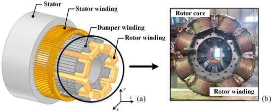
Figure 1.
Wound rotor synchronous generator. (a) Analysis model. (b) Rotor core experimental model.

Table 1.
Specification of the 900 kW-class WRSG.
In general, the core material used in an electrical machine has a nonlinear property and, to analyze this nonlinearity, a nonlinear MEC is constructed. Considering the periodic properties, it is expressed as a combination of 2T poles and 24T slots, where T is the number of periods. The paths that the magnetic flux passes through are divided into stator, rotor, air-gap, and inter-polar regions. A nonlinear MEC comprising reluctance in each region can be seen in Figure 2 and Figure 3. For simple nonlinear analysis, the damper windings of the rotor are neglected.
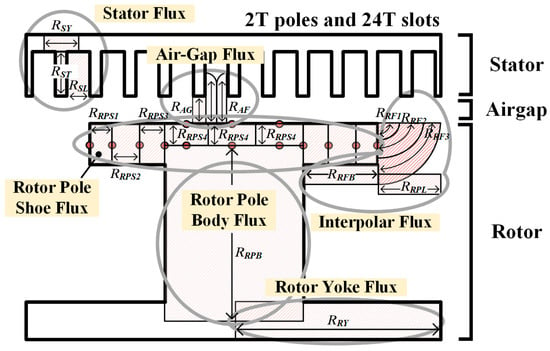
Figure 2.
Construction of nonlinear MEC.
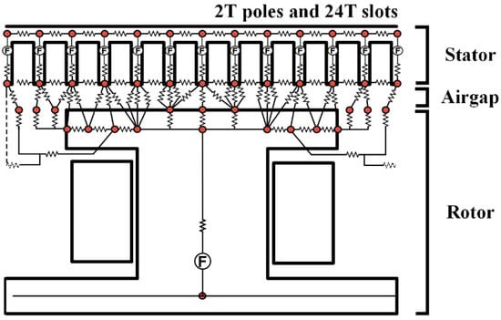
Figure 3.
Nonlinear MEC.
2.1. Configuration of Stator and Rotor Nonlinear MEC
To model the nonlinear reluctance circuit, KVL is applied to each loop, and the matrix is as follows:
is the permeance matrix, is the magnetomotive force (MMF), and is the magnetic flux that circulates in the closed loop. The MMF of each rotor teeth can be expressed as follows:
The more subdivided the path of the magnetic flux, the more accurate the results that can be obtained. However, one of its disadvantages is the prolonged computational time.
Therefore, it is important to configure a suitable reluctance circuit in each area [5]. The section of the rotor pole and inter-polar is divided into six sections. The reluctances in each section are as follows:
where is the width of the pole shoe, is the width of the pole body, is the number of the pole section, and is the core depth length. is the length given by
where is the distance from the center of the rotor pole body to the end of the rotor pole shoe. The reluctance of the straight air-gap magnetic flux and the reluctance that has to consider the fringing effect can be calculated as follows:
where is the length of the air gap, and is the width of the slot opening. The reluctance of the stator and rotor core is calculated as follows:
where is the length of the stator and rotor core, and is the width of the stator and rotor core. For the calculation of other reluctances—slot leakage reluctance between stator teeth () [14], reluctance generated from both sides of the rotor shoe (), fringing reluctance through the bottom of the rotor pole tip (), and leakage reluctance between two adjacent rotor poles ()—refer to [10]. To solve the nonlinear characteristic, can be calculated as in iteration Equation (8)
where and are the permeability of the MEC and B–H curve. and are the iteration number and error rate.
2.2. Configuration of Axis MEC
This section describes the axis reluctance configuration for the calculation of the initial value of the inductance that occurs in a one-phase winding. Owing to the variation of the inductance of the machine with a salient pole structure depending on the position of the rotor, the MEC is constructed by dividing it into a d axis and q axis. For simplicity, the effect on the stator of the field winding was neglected.
The magnetic flux line and reluctance circuit configuration when the rotor is on the q axis and d axis are shown in Figure 4 and Figure 5, respectively. It is evident that the magnetic flux path depends on the rotor position, and the MEC is also different. The leakage flux between the slot and tooth, between the windings to which the current is applied, is neglected and is similar to the magnitude of the reluctance described in the previous section. The pole body reluctance of the d axis should be set to the opposite cross-sectional area and length. Using the point of the initial specific permeability in an unsaturated core, the reluctance of the core was calculated.
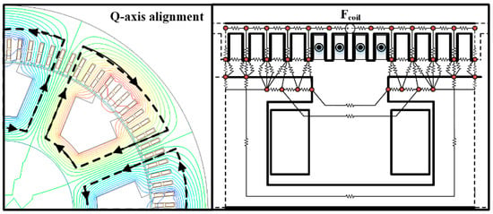
Figure 4.
Q axis magnetic flux line and construction of MEC.
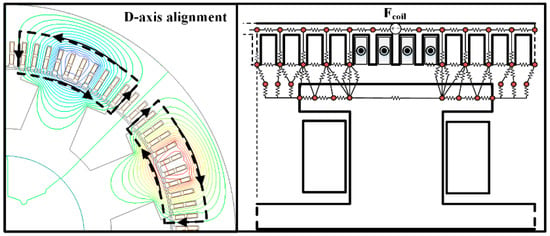
Figure 5.
D axis magnetic flux line and construction of MEC.
In Figure 6a, the B–H curve and μr–H curve graph of the rotor core are shown. In the μr–H curve, it can be seen that the initial permeability value in which the rotor core is in an unsaturated region has a constant value. Using this initial permeability, the initial inductance of the stator windings was calculated. The inductance used to confirm the power generation characteristics of the generator must have an inductance value in which saturation is taken into consideration, because the core is saturated during the operation of the generator. The magnetic flux, according to the axis positions of one-phase winding, was obtained using the reluctance network constructed in Figure 4 and Figure 5.
where is the reluctance constructed from Figure 4 and Figure 5, is the number of stator turns, and is the stator current.
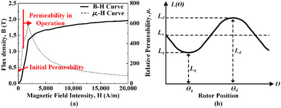
Figure 6.
(a) B–H curve of rotor core material. (b) Inductance change according to rotor position.
3. Calculations of Electrical Parameters
To verify the electromagnetics and performance of WRSG, electrical circuit parameters—such as back electromotive force (EMF), phase inductance, and phase resistance—are required. Electrical circuit parameters can be obtained through the proposed analysis and the MEC.
3.1. Resistance
The WRSG should not only consider the stator winding resistance but also the rotor winding resistance. This is because rotor winding also causes copper losses in electro- magnetic properties, which affects electromagnetic efficiency; however, only the stator phase resistance is used because the rotor winding resistance is not required in the performance measurement. The stator resistance per phase can be calculated as in (10)
where is the electrical resistivity of the conductor, is the winding length per turn, and is the cross-sectional area of the coil.
3.2. Inductance
In Figure 6b, the inductance according to the rotor position is shown. The inductance of one-phase winding can be obtained from the magnetic flux obtained using the axis reluctance network. The stator leakage inductance was neglected. The axis inductance of the one-phase winding is as follows:
where is the winding factor.
3.3. Back EMF
The flux linkage to one-phase windings can be derived as
where is the number of series turns per phase, and is the electrical angle. Back EMF can be derived by the differentiation of the linkage flux per phase according to the electrical rotation period, as follows:
3.4. Generating Characteristic Analysis
Using the electromagnetic circuit parameters—such as a back EMF, phase inductance, phase resistance, and load resistance for one-phase—generating characteristics can be predicted. In Figure 7, the equivalent circuit for one-phase and circuit parameters are shown. Phase current can be derived as
where is the synchronous reactance calculated by . Terminal voltage also can be derived as
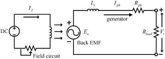
Figure 7.
Equivalent circuit of one-phase WRSG.
Output power can be derived as
through , it is possible to know the output power from the three-phase and generator performance [15].
4. Verification of MEC Analysis
Figure 8 shows the experimental setup for WRSG. A turbine was used as the mechanical input power of the generator. The back EMF and short-circuit current were measured while increasing the magnitude of the field current.
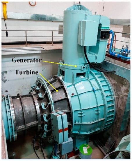
Figure 8.
Experimental setup for WRSG.
In Table 2, the MEC, FEM, and experimental results of the electrical circuit parameters are shown. A field current of 215 A was applied to the rotor winding, and the inductance required for the power generation characteristics was calculated using the permeability calculated by the nonlinear MEC. The inductance calculated by the MEC method contains a significant error compared to the FEM, which is a reasonable result because it is difficult to accurately represent the leakage path in the MEC method. The maximum size of the air-gap flux density according to the field current is compared with the FEM result and is shown in Figure 9. In addition, the waveform of the air-gap magnetic flux density, when a field current of 150 A is applied, can be seen in Figure 10, and the linkage flux results are shown in Figure 11. In the open circuit, when driven at a constant speed, the back EMF can be measured according to the magnitude of the field current, and the experimental results are compared with the FEM and MEC as shown in Figure 12. Figure 13 shows the short-circuit current of the generator and is compared with the FEM, MEC, and experimental data. As a result of the comparison of the magnitude of the short-circuit current depending on the magnitude of the field current, a small error was confirmed in the inductance obtained using the value of the initial relative permeability. The generation characteristic analysis at the rated speed is shown in Figure 14. A comparison of the MEC and FE results shows that the rated output point is accompanied by a small error. It seems that the error is the result of the electromagnetic parameters error. Nevertheless, it shows an insignificant error in the region where the voltage regulation decreases (VR < 15%). From a comparison with the MEC, FE, and experimental results, the MEC predictions are validated.

Table 2.
FEM and MEC results of electrical parameter (Field current: 215 A).
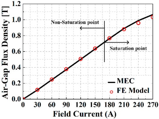
Figure 9.
Comparison of magnitude of flux density in air gap.
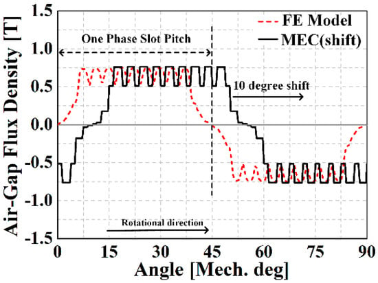
Figure 10.
Comparison of flux density waveform (field current: 150 A).
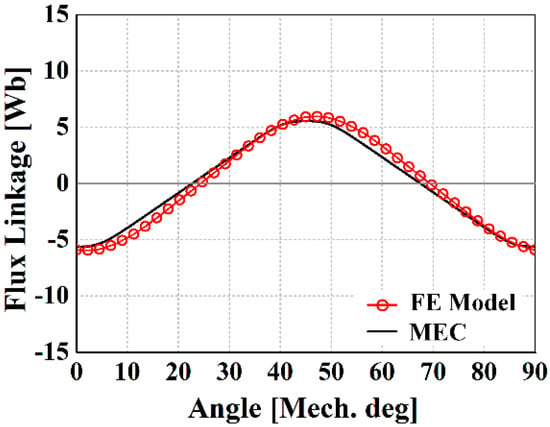
Figure 11.
Comparison of linkage flux waveform.
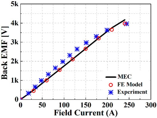
Figure 12.
Comparison of back EMF values as the field current changes.
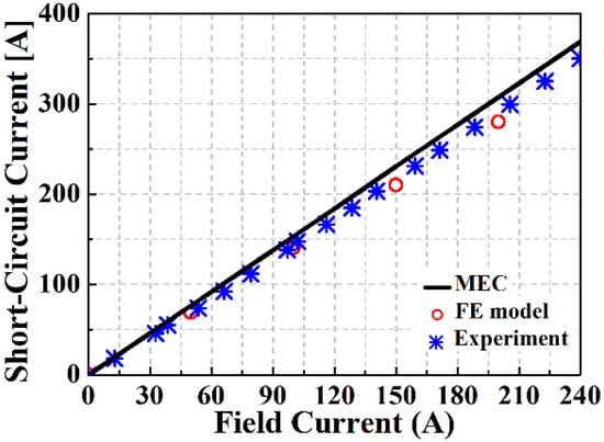
Figure 13.
Comparison of short-circuit current values as the field current changes.
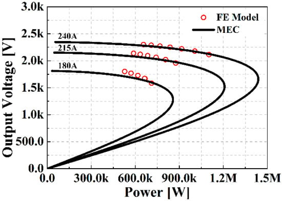
Figure 14.
Comparison of the power–voltage curve (FE model vs. MEC).
5. Conclusions
In this study, a nonlinear MEC analysis of a WRSG with a salient pole structure was performed. To calculate the inductance, a magnetic circuit was constructed by confirming the axis magnetic flux flow. From the result of the MEC, the electromagnetic parameter could be obtained, and the power generation characteristic of the generator could be predicted from the electromagnetic parameter. The proposed MEC method was validated by comparing the FE results with the experimental results. This proposed method can be used as an initial model when designing a WRSG.
Author Contributions
J.-Y.C.: conceptualization and supervision; H.-S.S.: software and writing—original draft preparation; D.-Y.K.: experiment and formal analysis; J.-H.W.: experiment and data curation; H.-K.L.: experiment and data curation. All authors have read and agreed to the published version of the manuscript.
Funding
This work was supported by the Korea Institute of Energy Technology Evaluation and Planning (KETEP) and the Ministry of Trade, Industry & Energy (MOTIE) of the Republic of Korea. (No. 20183010025420). This research was supported by the Basic Science Research Program through the National Research Foundation of Korea (NRF-2020R1A4A2002021).
Institutional Review Board Statement
Not applicable.
Informed Consent Statement
Not applicable.
Data Availability Statement
The data presented in this study are available on request from the corresponding author.
Conflicts of Interest
The authors declare no conflict of interest.
References
- Nuzzo, S.; Degano, M.; Galea, M.; Gerada, C.; Gerada, D.; Brown, N. Improved Damper Cage Design for Salient-Pole Synchronous Generators. IEEE Trans. Ind. Electron. 2017, 64, 1958–1970. [Google Scholar] [CrossRef] [Green Version]
- Griffo, A.; Drury, D.; Sawata., T.; Mellor, P.-H. Sensorless Starting of a Wound-Field Synchronous Starter/Generator for Aerospace Applications. IEEE Trans. Ind. Electron. 2012, 59, 3579–3587. [Google Scholar] [CrossRef]
- Wang, Q.; Zou, J.; Zhao, M. Analysis and Computer-Aided Simulation of Cogging Force Characteristic of a Linear Electromagnetic Launcher with Tubular Transverse Flux Machine. IEEE Trans. Plasma. Sci. 2011, 39, 157–161. [Google Scholar] [CrossRef]
- Cheng, M.; Chau, K.-T.; Chan, C.-C.; Zhou, E.; Huang, X. Nonlinear Varying-Network Magnetic Circuit Analysis for Doubly Salient Permanent-Magnet Motors. IEEE Trans. Magn. 2000, 36, 339–348. [Google Scholar] [CrossRef]
- Bash, M.; Williams, J.; Pekarek, S. Incorporating Motion in Mesh-Based Magnetic Equivalent Circuits. IEEE Trans. Energy Convers. 2010, 25, 329–338. [Google Scholar] [CrossRef]
- Wang, R.; Bash, M.; Pekarek, S.; Larson, A.; Maaren, R.-V. A Voltage Input-Based Magnetic Equivalent Circuit Model for Wound Rotor Synchronous Machines. In Proceedings of the 2013 International Electric Machines & Drives Conference, Chicago, IL, USA, 12–15 May 2013. [Google Scholar]
- Bash, M.; Pekarek, S. Analysis and Validation of a Population-Based Design of a Wound-Rotor Synchronous Machine. IEEE Trans. Energy Convers. 2012, 27, 603–614. [Google Scholar] [CrossRef]
- Bash, M.; Pekarek, S. Modeling of salient-pole wound-rotor synchronous machines for population-based design. IEEE Trans. Energy Convers. 2011, 26, 381–392. [Google Scholar] [CrossRef]
- Derbas, H.-W.; Williams, J.-M.; Koenig, A.-C.; Pekarek, S. A Comparison of Nodal- and Mesh-Based Magnetic Equivalent Circuit Models. IEEE Trans. Energy Convers. 2009, 24, 388–396. [Google Scholar] [CrossRef] [Green Version]
- Wang, R.; Pekarek, S.; Bash, M.; Larson, A.; Maren, R. Incorporating Dynamics in a Mesh-Based Magnetic Equivalent Circuit Model of Synchronous Machines. IEEE Trans. Energy Convers. 2015, 30, 821–832. [Google Scholar] [CrossRef]
- Ostovic, V. A Novel Method of Evaluation of Transient States in Saturated Electrical Machines. IEEE Trans. Ind. Appl. 1989, 25, 96–100. [Google Scholar] [CrossRef]
- Yao, L. Magnetic Field Modeling of Machine and Multiple Machine Systems Using Dynamic Reluctance Mesh Modeling. Ph.D. Thesis, University of Nottingham, Nottingham, UK, 2006. [Google Scholar]
- Lee, J.-J.; Lee, J.; Kim, K.-S. Design of a WFSM for Electric Veicle Based on a Nonlinear Magnetic Equivalent Circuit. IEEE Trans. Appl. Supercon. 2018, 28, 5206304. [Google Scholar] [CrossRef]
- Lipo, T.-A. Introduction to AC Machine Design, 2nd ed.; Wisconsin Power Electronics Research Center: Madison, WI, USA, 2004; pp. 79–124. [Google Scholar]
- Shin, K.-H.; Jung, K.-H.; Cho, H.-W.; Choi, J.-Y. Analytical Modeling and Experimental Verification for Electromagnetic Analysis of Tubular Linear Synchronous Machines with Axially Magnetized Permanent Magnets and Flux-Passing Iron Poles. IEEE Trans. Magn. 2018, 54, 8204006. [Google Scholar] [CrossRef]
Publisher’s Note: MDPI stays neutral with regard to jurisdictional claims in published maps and institutional affiliations. |
© 2021 by the authors. Licensee MDPI, Basel, Switzerland. This article is an open access article distributed under the terms and conditions of the Creative Commons Attribution (CC BY) license (https://creativecommons.org/licenses/by/4.0/).