
FMEA and Risks Assessment for Thermochemical Energy Storage Systems Based on Carbonates

 , ,
, ,  ,
,  and
and
Abstract
:1. Introduction
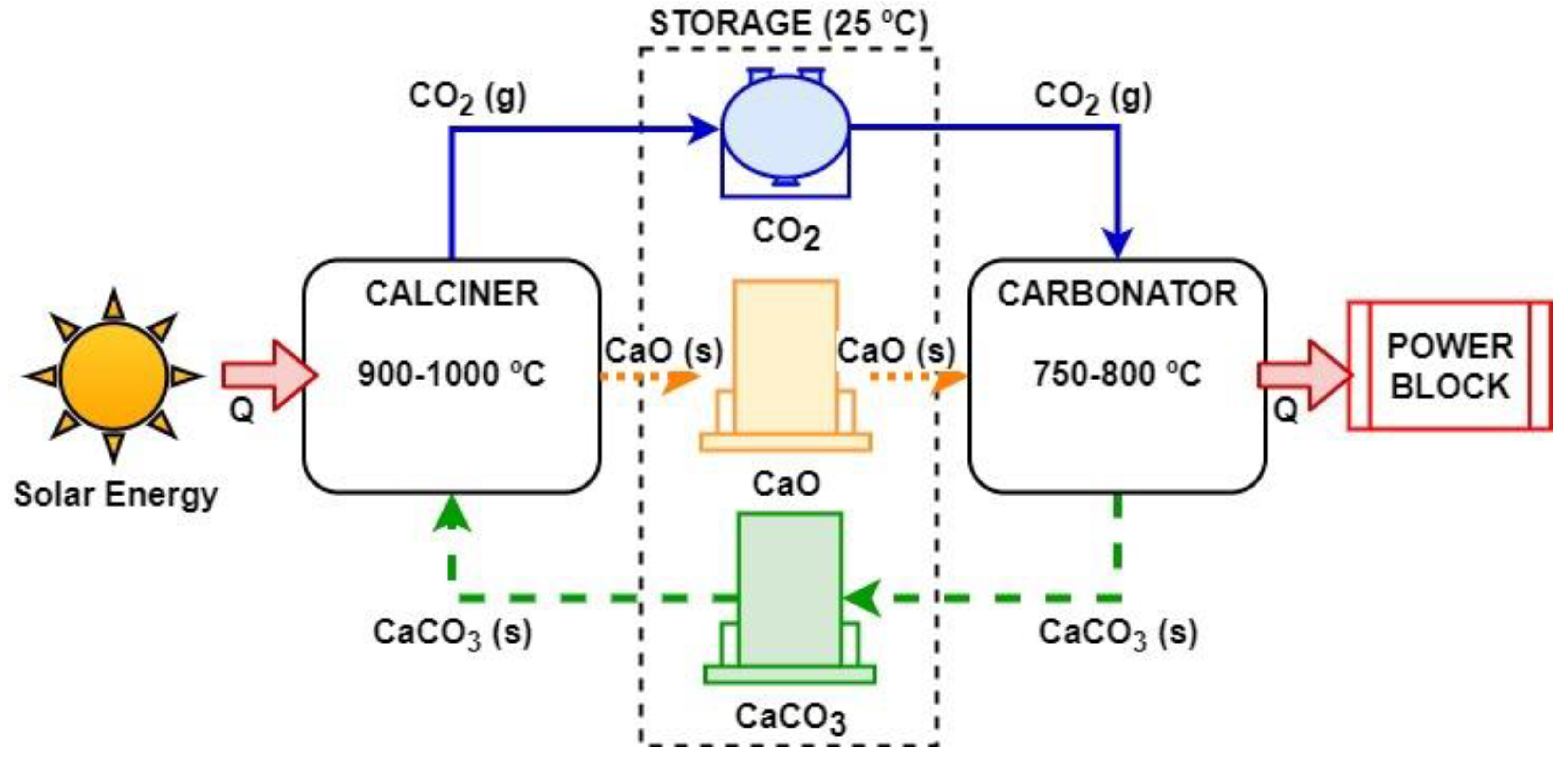
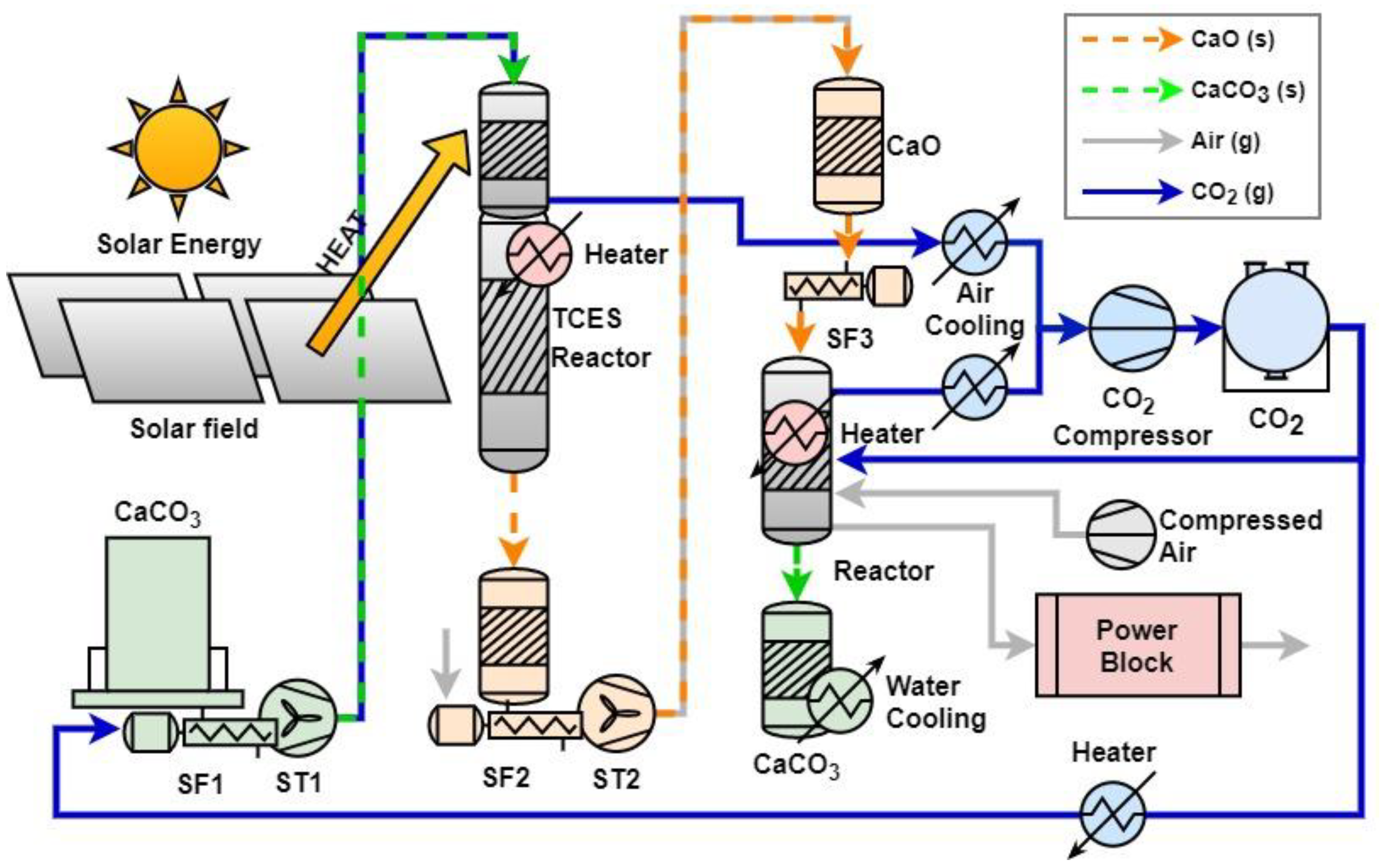
2. A Real Case of Study: Developing a KW-Scale CSP–CaL Prototype
3. CSP–CaL Prototype Risk Assessment
- Nature and types of risks assessed.
- Definition of likelihood (Table A1 in Appendix A).
- Definition of consequences of the risk. The consequences will be described quantitatively as a function of its impact on the project’s objectives (Table A2 in Appendix A).
- Definition of the risk level. It is the magnitude of risk or combination of risks, expressed in terms of probability and consequence combination. Depending on the level of the risk, it is classified as low, medium, moderate, high, very high, or extreme risk.
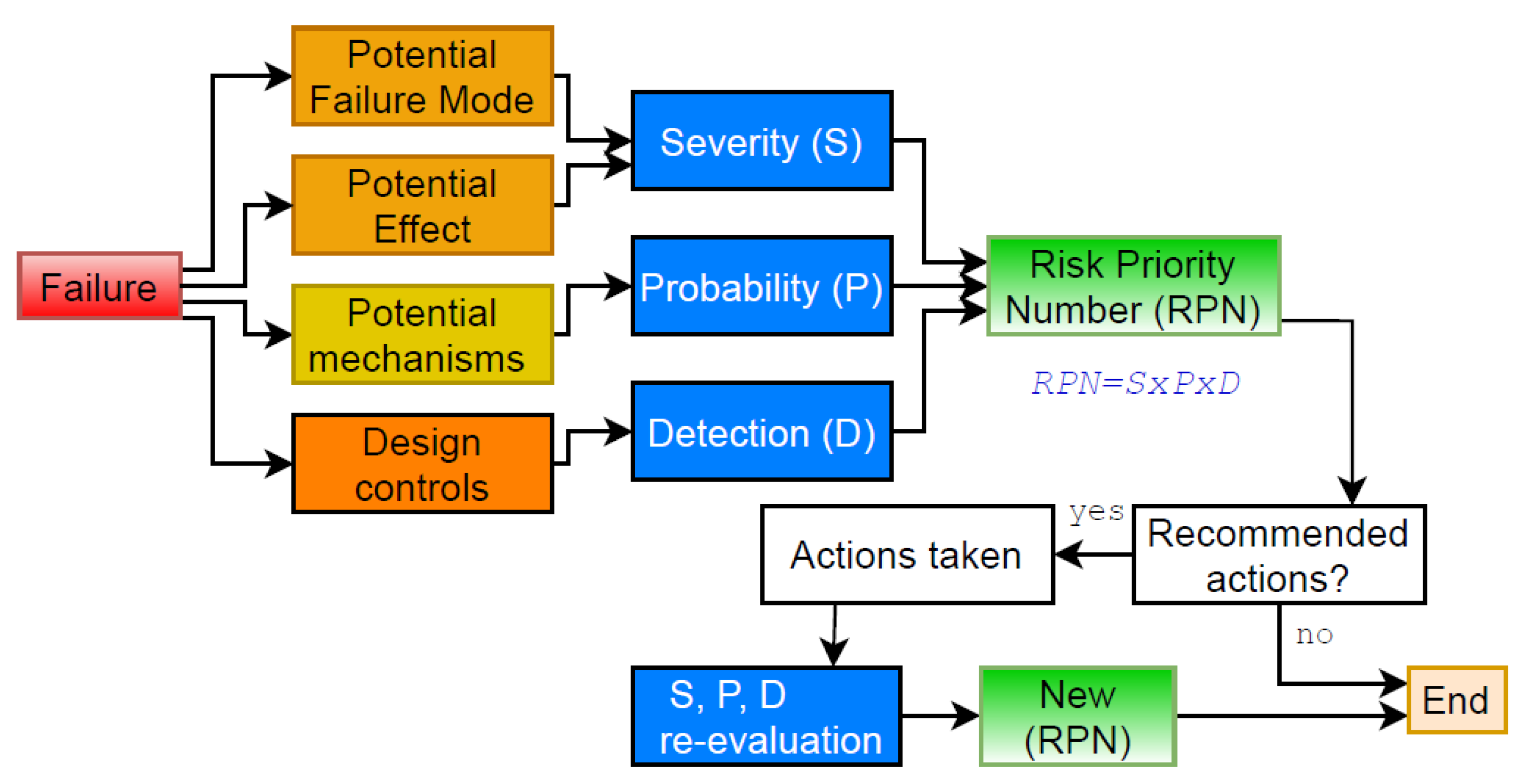
4. Product and Process Failure-Mode Effect and Analysis (FMEA)
4.1. Evaluation Method and Risk Criteria
4.2. FMEA Analysis for the CSP–CaL Prototype Operation and Testing
4.3. Contingency Measurements
5. Discussion
6. Conclusions
Author Contributions
Funding
Institutional Review Board Statement
Informed Consent Statement
Conflicts of Interest
Appendix A

| Likelihood | |
|---|---|
| E Almost certain | The event is expected to occur on a regular basis. The probability of occurring is greater than 90%. |
| D Likely | The event is expected to occur from time to time. The probability of occurring is between 60 and 90%. |
| C Possible | The event could occur at the same time. The probability of occurring is between 40 and 60%. |
| B Unlikely | Event not expected, but it is possible that one could occur. The probability of occurring is between 10 and 40%. |
| A Rare | The event will only occur in exceptional circumstances. The probability of occurring is less than 10%. |
| Consequence | |
|---|---|
| 5 Severe | If it occurs, a risk event will have a severe impact on achieving desired results, to the extent that one or more of its critical outcome objectives will not be achieved. |
| 4 Major | If it occurs, a risk event will have a significant impact on achieving desired results, to the extent that one or more stated outcome objectives would fall below acceptable levels. |
| 3 Moderate | If it occurs, a risk event will have a major impact on achieving desired results, to the extent that one or more stated outcome objectives would fall below goals but above minimum acceptable levels. |
| 2 Minor | If it occurs, a risk event will have a minor impact on achieving desired results, to the extent that one or more stated outcome objectives will fall below goals but well above minimum acceptable levels. |
| 1 Insignificant | If it occurs, a risk event will have little or no impact on achieving outcome objectives. |
| Effect | Severity | Ranking |
|---|---|---|
| Hazardous without warning | Very high severity ranking when a potential failure mode effects safe system operation without warning. | 10 |
| Hazardous with warning | Very high severity ranking when a potential failure mode affects safe system operation with warning. | 9 |
| Very high | The system is inoperable with destructive failure without compromising safety. | 8 |
| High | The system is inoperable with equipment damage. | 7 |
| Moderate | The system is inoperable with minor damage. | 6 |
| Low | The system is inoperable without damage. | 5 |
| Very low | The system is operable with significant degradation of performance. | 4 |
| Minor | The system is operable with some degradation of performance. | 3 |
| Very Minor | The system is operable with minimal interference. | 2 |
| None | No effect. | 1 |
| Probability | Ranking | |
|---|---|---|
| Very High: failure is almost inevitable | >1 in 2 | 10 |
| Hazardous with warning | 1 in 3 | 9 |
| High: repeated failures | 1 in 8 | 8 |
| High | 1 in 20 | 7 |
| Moderate: occasional failures | 1 in 80 | 6 |
| Low | 1 in 400 | 5 |
| Very low | 1 in 2000 | 4 |
| Low: relatively few failures | 1 in 15,000 | 3 |
| Very Minor | 1 in 150,000 | 2 |
| Remote: failure is unlikely | <1 in 1,500,000 | 1 |
| Detection | Likelihood of Detection by Design Control | Ranking |
|---|---|---|
| Absolute uncertainty | Design control cannot detect potential cause/mechanism and subsequent failure mode. | 10 |
| Very remote | Very remote chance the design control will detect potential cause/mechanism and subsequent failure mode. | 9 |
| Remote | Remote chance the design control will detect potential cause/mechanism and subsequent failure mode. | 8 |
| Very low | Very low chance the design control will detect potential cause/mechanism and subsequent failure mode. | 7 |
| Low | Low chance the design control will detect potential cause/mechanism and subsequent failure mode. | 6 |
| Moderate | Moderate chance the design control will detect potential cause/mechanism and subsequent failure mode. | 5 |
| Moderately high | Moderately high chance the design control will detect potential cause/mechanism and subsequent failure mode. | 4 |
| High | High chance the design control will detect potential cause/mechanism and subsequent failure mode. | 3 |
| Very high | Very high chance the design control will detect potential cause/mechanism and subsequent failure mode. | 2 |
| Almost certain | Design control will detect potential cause/mechanism and subsequent failure mode. | 1 |
References
- Kiefer, C.P.; Caldés, N.; Del Río, P. Will dispatchability be a main driver to the European Union cooperation mechanisms for concentrated solar power? Energy Sources Part B Econ. Plan. Policy 2021, 16, 42–54. [Google Scholar] [CrossRef]
- National Renewable Energy Laboratory (NREL) Concentrating Solar Power Projects. Available online: https://www.nrel.gov/csp/solarpaces/index.cfm (accessed on 1 July 2018).
- Goods, S.H.; Bradshaw, R.W. Corrosion of Stainless Steels and Carbon Steel by Molten Mixtures of Commercial Nitrate Salts. J. Mater. Eng. Perform. 2004, 13, 78–87. [Google Scholar] [CrossRef]
- Vignarooban, K.; Xu, X.; Arvay, A.; Hsu, K.; Kannan, A.M. Heat transfer fluids for concentrating solar power systems—A review. Appl. Energy 2015, 146, 383–396. [Google Scholar] [CrossRef]
- Kearney, D.; Kelly, B.; Herrmann, U.; Cable, R.; Pacheco, J.; Mahoney, R.; Price, H.; Blake, D.; Nava, P.; Potrovitza, N. Engineering aspects of a molten salt heat transfer fluid in a trough solar field. Energy 2004, 29, 861–870. [Google Scholar] [CrossRef]
- André, L.; Abanades, S.; Flamant, G. Screening of thermochemical systems based on solid-gas reversible reactions for high temperature solar thermal energy storage. Renew. Sustain. Energy Rev. 2016, 64, 703–715. [Google Scholar] [CrossRef]
- Sunku Prasad, J.; Muthukumar, P.; Desai, F.; Basu, D.N.; Rahman, M.M. A critical review of high-temperature reversible thermochemical energy storage systems. Appl. Energy 2019, 254, 113733. [Google Scholar] [CrossRef]
- Alovisio, A.; Chacartegui, R.; Ortiz, C.; Valverde, J.M.; Verda, V. Optimising the CSP-Calcium Looping integration for Thermochemical Energy Storage. Energy Convers. Manag. 2017, 136, 85–98. [Google Scholar] [CrossRef]
- Chacartegui, R.; Alovisio, A.; Ortiz, C.; Valverde, J.M.M.; Verda, V.; Becerra, J.A.A. Thermochemical energy storage of concentrated solar power by integration of the calcium looping process and a CO2 power cycle. Appl. Energy 2016, 173, 589–605. [Google Scholar] [CrossRef]
- Hanak, D.P.; Michalski, S.; Manovic, V. From post-combustion carbon capture to sorption-enhanced hydrogen production: A state-of-the-art review of carbonate looping process feasibility. Energy Convers. Manag. 2018, 177, 428–452. [Google Scholar] [CrossRef]
- Zimon, D.; Madzík, P. Standardized management systems and risk management in the supply chain. Int. J. Qual. Reliab. Manag. 2019, 37, 305–327. [Google Scholar] [CrossRef]
- Khan, A.S.; Salah, B.; Zimon, D.; Ikram, M.; Khan, R.; Pruncu, C.I. A Sustainable Distribution Design for Multi-Quality Multiple-Cold-Chain Products: An Integrated Inspection Strategies Approach. Energies 2020, 13, 6612. [Google Scholar] [CrossRef]
- Xiao, N.; Huang, H.Z.; Li, Y.; He, L.; Jin, T. Multiple failure modes analysis and weighted risk priority number evaluation in FMEA. Eng. Fail. Anal. 2011, 18, 1162–1170. [Google Scholar] [CrossRef]
- Krüger, M.; Haunstetter, J.; Knödler, P.; Zunft, S. Slag as an inventory material for heat storage in a concentrated solar tower power plant: Design studies and systematic comparative assessment. Appl. Sci. 2019, 9, 1833. [Google Scholar] [CrossRef] [Green Version]
- Bubbico, R.; Greco, V.; Menale, C. Hazardous scenarios identification for Li-ion secondary batteries. Saf. Sci. 2018, 108, 72–88. [Google Scholar] [CrossRef]
- Purushothaman, S. Prioritizing Battery Management System Functionalities for Risk Mitigation. In Proceedings of the 2019 IEEE Industry Applications Society Annual Meeting, Baltimore, MD, USA, 29 September–3 October 2019; pp. 1–5. [Google Scholar] [CrossRef]
- Casamirra, M.; Castiglia, F.; Giardina, M.; Lombardo, C. Safety studies of a hydrogen refuelling station: Determination of the occurrence frequency of the accidental scenarios. Int. J. Hydrogen Energy 2009, 34, 5846–5854. [Google Scholar] [CrossRef]
- Animah, I.; Shafiee, M. Application of risk analysis in the liquefied natural gas (LNG) sector: An overview. J. Loss Prev. Process Ind. 2020, 63, 103980. [Google Scholar] [CrossRef]
- Chen, Y.C.; Wu, W.F. Constructing an effective prevention mechanism for MSW lifecycle using failure mode and effects analysis. Waste Manag. 2015, 46, 646–652. [Google Scholar] [CrossRef]
- Socratces Project—Competitive & Sustainable Concentrated Solar Plants. Available online: https://socratces.eu/public-library/ (accessed on 1 April 2021).
- Chacartegui, R.; Ortiz, C.; Pérez-maqueda, L.A.; Hills, T.; Romeo, L.M.; Schories, G.; Lorenzo, A.; Grippa, M.; Lemonidou, A.; Valverde, J.M. Solar Calcium-Looping Integration for Thermochemical Energy Storage: SOCRATCES Project. Available online: https://cordis.europa.eu/project/id/727348 (accessed on 1 April 2021).
- SOCRATCES Project Consortium Socratces Project. Available online: https://socratces.eu/ (accessed on 1 April 2021).
- Shimizu, T.; Hirama, T.; Hosoda, H.; Kitano, K.; Inagaki, M.; Tejima, K. A twin fluid-bed reactor for removal of CO2 from combustion processes. Chem. Eng. Res. Des. 1999, 77, 62–68. [Google Scholar] [CrossRef]
- Ortiz, C.; Valverde, J.M.; Chacartegui, R.; Pérez-Maqueda, L.A.; Gimenez-Gavarrell, P. Scaling-up the Calcium-Looping Process for CO2 Capture and Energy Storage. KONA Powder Part. J. 2021, 38, 189–208. [Google Scholar] [CrossRef] [Green Version]
- Ortiz, C.; Chacartegui, R.; Valverde, J.M.M.; Alovisio, A.; Becerra, J.A.A. Power cycles integration in concentrated solar power plants with energy storage based on calcium looping. Energy Convers. Manag. 2017, 149, 815–829. [Google Scholar] [CrossRef]
- Ortiz, C.; Valverde, J.M.; Chacartegui, R.; Perez-Maqueda, L.A.; Giménez, P. The Calcium-Looping (CaCO3/CaO) process for thermochemical energy storage in Concentrating Solar Power plants. Renew. Sustain. Energy Rev. 2019, 113, 109252. [Google Scholar] [CrossRef]
- Albliwi, S.A.; Antony, J.; Arshed, N.; Ghadge, A. International Journal of Quality & Reliability Management. Int. J. Qual. Reliab. Manag. 2017, 34, 508–529. [Google Scholar]
- Stamatis, D.H. Risk Management Using Failure Mode and Effect Analysis (FMEA); ASQ Quality Press: Milwaukee, WI, USA, 2019; ISBN 9780873899789. [Google Scholar]
- Chen, J.K. Utility Priority Number Evaluation for FMEA. J. Fail. Anal. Prev. 2007, 7, 321–328. [Google Scholar] [CrossRef]
- Constantin, A.; National, M.; Stefan, H.; Independent, M. Risk assessment of thermal power plant. Rev. Energ. 2009, 57, 627–630. [Google Scholar]
- Shrivastava, R.; Patel, P. Hazards Identification and Risk Assessment in Thermal Power Plant. Int. J. Eng. Res. Technol. 2014, 3, 463–466. [Google Scholar]


| Risk ID | Description and Consequences | Source of Risk | Mitigation Action |
|---|---|---|---|
| R1 | Delays in transferring information/ components/ modules between partners suppliers and EPC companies for prototype integration (includes material exchange) | Modules design and construction | Management board controls. Clear definition of responsibilities Consider alternative pathways to advance in construction activities until the reception of information to avoid accumulated delays Identification of alternative systems for temporal substitution of modules or components with delays/failures |
| R2 | Non-adequate correspondence of plans and components | Modules design and construction | Clear definition in the action plan of the responsibility for information transmission. |
| R3 | Differences in modules information availability and accuracy. | Results integration | Following of results and data quality |
| R4 | Issues in modules construction, transport, or erection | Modules construction | Clear definition in the action plan of the responsibilities for task implementation and times |
| R5 | Problems with prototypes location (legal constraints, delays in permits, etc.) | Prototype construction | Participation of specialized technicians for legal framework and documents |
| R6 | Appear unexpected new results and technological challenges, critical component breakdown, unexpected low performance | Technology watch | Technologies evaluated at different levels of integration, in a sequential process, from laboratory to demonstrators, to identify separate effectsRedesign of alternatives |
| R7 | The appearance of new requisites of technologies, new regulations or changes in costs or materials availability | Technology watch | Project’s technology watch must deliver information periodically to maintain a continuous flow of information |
| R8 | Non-unexpected availability (or delays) for implementing in demonstrator location | Prototype construction | Flexibility for readapting modules. Periodical meetings to identify alternative solutions |
| Risk Level | Prototype Construction | Consequence | |||||
|---|---|---|---|---|---|---|---|
| Insignificant | Minor | Moderate | Major | Severe | |||
| Low | Likehood | Rare | |||||
| Medium | Unlikely | R3-R6-R7 | R2 | ||||
| High | Possible | R1 | R5-R8 | ||||
| Very high | Likely | R4 | |||||
| Extreme | Almost Certain | ||||||
| Risk ID | Description and Consequences | Source of Risk | Mitigation Action |
|---|---|---|---|
| R9 | Delays in laboratory facilities startup. Non-availability for testing equipment | Planning | Laboratory facilities startup with adequate time before starting main activities. |
| R10 | Inconsistent measures from different sources | Measurement equipment and protocols | Setting of templates and standards for data collecting and information presentation at the beginning of the tasks. |
| R11 | Incorrect records keeping | Data management | Clear definition in the Action plan of the responsibilities for information keeping at each subsequent step. |
| R12 | Low availability of demonstration cases/modules testing | Modules construction | Definition in the action plan of strategies for validation of modules. |
| R13 | Excessive fatigue of materials of construction due to cyclic operation | Materials failure | The materials of construction must be chosen for their ability to withstand high temperature and still perform mechanically. Regular programmed materials inspection will be performed to avoid catastrophic failures. The reactors should be designed to be extracted and replaced (if needed) for mechanical and material analyses after operation time. |
| R14 | Disfigurement of units due to differential thermal expansion at high temperatures (calciner and carbonator operation up to 1000 °C) | Magnitudes resizing with operation and heating | Lateral fixations should be included to allow displacements. System includes monitoring of displacement. Need for a control system actuation to avoid disfigurement or structural damages. |
| R15 | High emissivity losses leading to unexpected results | Heat losses at solar receiver | The receiver’s cavity design should be selected based on its better ability to retain radiation than others (e.g., a bare tube). At prototype; Integration of measures to control surface absorptivity and beam down (low emissivity losses design). Absorptivity losses evaluated and included in calculations |
| R16 | Errors in programming the control software cause malfunctions, e.g., an incomplete reaction in the carbonization process | Incomplete tested control software for the carbonator | Simulating the control software as far as possible; foreseen remote access to fix errors remotely. |
| R17 | Bad data acquisition and observation | An incomplete programmed master control unit (MCU) | Remote access to the MCU to fix any errors quickly. |
| R18 | Loss of remote control and loss of data acquisition | Control | Duplicate control system in the equipment for automatic stop procedure and position of components. |
| R19 | Potential inadequate operation on systems | Control | Commissioning procedure for labeling. Periodic revision status. |
| Risk Level | Operation and Testing Likelihood | Consequence | |||||
|---|---|---|---|---|---|---|---|
| Insignificant | Minor | Moderate | Major | Severe | |||
| Low | Rare | ||||||
| Medium | Unlikely | R12 | R16 | R13-R14 | |||
| High | Possible | R10-R11-R17 | R9-R15 | R18-R19 | |||
| Very high | Likely | ||||||
| Extreme | Almost Certain | ||||||
| Item | System Devices, Component Failure Modes, and Potential Effects | SEV | PRO | DET | RPN | ||
|---|---|---|---|---|---|---|---|
| S1 | Electrical supply | Supplies. Electrical circuit breaker triggering | Installation without power supply. Elements position fixed—regulation capacity loss. | 4 | 4 | 2 | 32 |
| S2 | Compressed gas supply | Supplies. Compressed gas pressure loss | Installation without compressed gas supply. Pneumatic valves blocked. Effects on the reactors control system. | 6 | 5 | 2 | 60 |
| S3 | Compressed gas supply | Supplies. Compressed gas regulator valve failure | Installation without compressed gas supply. Regulation capacity lost. Overpressure in the system. | 6 | 5 | 2 | 60 |
| CD1 | CO2 compression and storage system | Communication loss with PLC | Loss of remote control. Loss of data acquisition. | 3 | 3 | 2 | 18 |
| CD2 | CO2 compression and storage system | Pressure transmitter failure | Overpressure on the tank. | 6 | 3 | 2 | 36 |
| CD3 | CO2 compression and storage system | Local electrical system failure | System out of operation. Loss of CO2 pressure and mass flow capacity reposition. | 4 | 3 | 2 | 24 |
| CD4 | CO2 compression and storage system | Compressor forced ventilation system failure | Overheating of the compressor. Effect on compressor operation and consumption. | 3 | 2 | 2 | 12 |
| CD5 | CO2 compression and storage system | Chiller failure | Overheating of CO2 supply to the tank. | 3 | 2 | 2 | 12 |
| CD6 | CO2 compression and storage system | Filters clogged—cyclone and bag-paper filter | Reduction of CO2 mass flow. Compressor higher power consumption, load and noise. | 2 | 4 | 3 | 24 |
| CD7 | CO2 compression and storage system | Regulation valves failure | CO2 compression and storage system. Insufficient pressure in the tank. Effect on calciner supply. | 3 | 2 | 3 | 18 |
| Item | System Devices, Component Failure Modes and Potential Effects | SEV | PRO | DET | RPN | ||
|---|---|---|---|---|---|---|---|
| C1 | Master control unit (MCU) | Programming error or malfunction | Loss of observation the overall process | 3 | 3 | 2 | 18 |
| C2 | Remote access to all control units | An outage of the Internet connection; Internal Network error | Loss of remote access to the overall process | 3 | 4 | 2 | 24 |
| C3 | External connections | Internet access failure | Loss of remote control. Loss of data acquisition | 6 | 5 | 3 | 90 |
| C4 | Equipment connections | Equipment communication failure | Loss of remote control. Loss of data acquisition | 4 | 5 | 2 | 40 |
| C5 | Equipment signals | Analog signal failure (from PLC). Wire cut or similar | Loss of remote control. Loss of data acquisition | 4 | 5 | 2 | 40 |
| SO1 | Solar field | Total Electrical power loss | Solar shape evolving over non protected areas | 5 | 2 | 2 | 20 |
| SO2 | Solar field | CO2 mass flow loss | Wall temperature increase | 5 | 2 | 2 | 20 |
| SO3 | Solar receiver | Communication loss | Concentrated solar flux drift. Solar shape evolving over non protected areas | 3 | 3 | 2 | 18 |
| SO4 | Solar field | High Wind Speed | Damages on Heliostats | 4 | 3 | 2 | 24 |
| SO5 | Solar field | Solar field. Heliostat Non-programmed movement in response to control actions | Solar shape evolving over non protected areas. Personnel risk if it happens during maintenance over the heliostats | 4 | 3 | 2 | 24 |
| SO6 | Solar receiver | Solar receiver. Cavity receiver material ingress (solid, liquid, gaseous) | Effects on the heat transfer. Potential damages on surfaces | 5 | 3 | 3 | 45 |
| PB1 | Power block | Cooling system failure | Failures on cooling system components: pump, fan, water spillage. Potential damage on engine | 4 | 4 | 2 | 32 |
| PB2 | Power block | Vibrations | Noise, deterioration, transmission to other components | 2 | 5 | 2 | 20 |
| PB3 | Power block | Electrical Power loss | Cooling system failure. Overheating | 6 | 4 | 2 | 48 |
| PB4 | Power block | Load loss in the mechanical couple | Risk of over-speed and engine damage | 6 | 3 | 2 | 36 |
| PB5 | Power block | Air valves | Engine performance affected | 3 | 3 | 3 | 27 |
| PB6 | Power block | PLC | Loss of remote control. Loss of data acquisition | 4 | 4 | 2 | 32 |
| Item | System Devices and Component Failure Modes | SEV | PRO | DET | RPN | ||
|---|---|---|---|---|---|---|---|
| RE1 | Clc Cbr | Instrumentation signal failure (as in thermocouples, mass flow meters, and other equipment) | Loss of control and identification of failures | 4 | 3 | 2 | 24 |
| RE2 | Clc Crb | PLC communication lost | Loss of remote control. Loss of data acquisition | 3 | 5 | 2 | 30 |
| RE3 | Clc Crb | Screw feeder failure | Speed regulator performance fails because control or blocking | 4 | 3 | 2 | 24 |
| RE4 | Clc | CO2 preheater failure | Cold CO2 in the calciner. Calcination process frozen. | 2 | 3 | 2 | 12 |
| RE5 | Clc | Pneumatic conveying system clogging | Pipes blocked. Non enough material arriving at the calciner | 3 | 6 | 2 | 36 |
| RE6 | Clc | Material wall deposition; clogging | Heat transfer penalized. Reaction penalized/stopped | 3 | 6 | 2 | 36 |
| RE7 | Clc Crb | CO2 mass flow controller failure | Loss of control and identification of operation situation | 3 | 4 | 2 | 24 |
| RE8 | Clc Crb | Vibrations in components; natural modes in the start-up or load changes | Noise, deterioration, transmission to other components | 2 | 5 | 2 | 20 |
| RE9 | Clc Crb | Wiring failure | Loss of signal. Loss of control. | 5 | 3 | 2 | 30 |
| RE10 | Clc | Nitrogen filter clogging | CO2 inertization at calciner exit affected | 4 | 5 | 2 | 40 |
| RE11 | Clc | Swappable vessel; overload control; solids level above the threshold | Hot material is accumulated inside the reactor. Potential agglomeration and damages on the valve | 5 | 3 | 2 | 30 |
| RE12 | Clc | Swappable vessel; shutter valve blocked | The bottom vessel cannot be isolated for movement | 4 | 2 | 2 | 16 |
| RE13 | Clc Crb | Counterweigh failure; unbalance | Movement of structure | 7 | 2 | 1 | 14 |
| RE14 | Clc Crb | Lighting strike | Damages on the equipment and personnel | 8 | 5 | 1 | 40 |
| RE15 | Clc | Material spillage | Pipes break, inadequate manipulation, failure in the control system. Cold material implies loss and dirt. Hot material is a risk for personnel | 8 | 2 | 2 | 32 |
| RE16 | Clc | Electrical power loss | Exothermic reaction control. Temperatures increase in some spots | 2 | 3 | 2 | 12 |
| RE17 | Clc Crb | Sensor mount-seal: compression set | Leak | 8 | 7 | 1 | 56 |
| RE18 | Clc | Sensor mount-seal: loosen during sensor assembly/service | Leak. Fall inside tank | 8 | 2 | 1 | 16 |
| RE19 | Clc Crb | Sensor mount-seal: damaged internal thread | Cannot install sensor | 5 | 2 | 1 | 10 |
| RE20 | Clc Crb | Sensor mount-seal: damaged external thread | Cannot install wire nut | 4 | 3 | 1 | 12 |
| RE21 | Clc | Hold-fluid flow-path heat-transfer structure: stress crack | Cooling does not work. Sudden refrigerant loss. | 8 | 8 | 2 | 128 |
| RE22 | Clc | Hold-fluid flow-path heat-transfer structure: stress crack | Leak. Loss of heat transfer. | 8 | 5 | 2 | 80 |
| RE23 | Clc | Hold-fluid flow-path heat-transfer structure: corrosion | Leak. Loss of heat transfer. | 8 | 7 | 5 | 280 |
| RE24 | Clc | Hold-fluid, flow-path heat-transfer structure: puncture | Leak. Loss of heat transfer. | 8 | 10 | 1 | 80 |
| RE25 | Clc | Hold-fluid flow-path heat-transfer structure: burst fail | Leak. Loss of heat transfer. | 8 | 2 | 5 | 80 |
| RE26 | Clc | Hold-fluid flow-path heat-transfer structure: plugged | Loss of heat transfer. Leakage due to increasing flow velocity | 8 | 7 | 1 | 56 |
| RE27 | Clc | Hold-fluid flow-path heat-transfer structure: ballooning | Leak. Loss of heat transfer. | 5 | 9 | 8 | 360 |
| RE28 | Clc Crb | Instrument air pressure loss, i.e., pneumatic control valve | Valve is in a fixed position without the capacity for control | 4 | 2 | 2 | 16 |
| RE29 | Clc | Bottom vessel, overload control, solids level | Hot material is accumulated inside the carbonator. Potential agglomeration and damages on the valves. | 4 | 5 | 2 | 40 |
| RE30 | Crb | Shutter valve blocked. | the bottom vessel cannot be isolated for movement | 4 | 5 | 2 | 40 |
| RE31 | Crb | Uncontrolled exothermic reactions | Overheating | 7 | 2 | 2 | 28 |
| RE32 | Crb | Inadequate labeling and signals of the components and their status | Potential inadequate operation on elements | 4 | 2 | 3 | 24 |
| RE33 | Crb | Filter on top of the vessel—clogging | Overpressure | 3 | 2 | 3 | 18 |
| RE34 | Crb | Filters on aeration lines—clogging | No air inserted on specific points. There is a wrong indication on pressure instruments | 3 | 3 | 3 | 27 |
| RE35 | Crb | Clamp joints: gasket—damaged sealing gasket | Gas leakage | 2 | 8 | 3 | 48 |
| RE36 | Crb | Screw feeder: inlet/outlet connections—bad seal | Gas leakage | 2 | 2 | 4 | 16 |
| RE37 | Crb | Screw feeder: mechanism—stop rotating, clogging | feeder power shut down | 5 | 5 | 2 | 50 |
| RE38 | Crb | Furnaces: ceramics—break | resistance short-circuit, resistance burn | 8 | 4 | 2 | 64 |
| RE39 | Crb | Furnaces: control—control failure | resistance burn | 8 | 1 | 1 | 8 |
| RE40 | Crb | Reactor: coil-cracking | Gas Leakage | 8 | 3 | 3 | 72 |
Publisher’s Note: MDPI stays neutral with regard to jurisdictional claims in published maps and institutional affiliations. |
© 2021 by the authors. Licensee MDPI, Basel, Switzerland. This article is an open access article distributed under the terms and conditions of the Creative Commons Attribution (CC BY) license (https://creativecommons.org/licenses/by/4.0/).
Share and Cite
Carro, A.; Chacartegui, R.; Tejada, C.; Gravanis, G.; Eusha, M.; Spyridon, V.; Simira, P.; Ortiz, C. FMEA and Risks Assessment for Thermochemical Energy Storage Systems Based on Carbonates. Energies 2021, 14, 6013. https://doi.org/10.3390/en14196013
Carro A, Chacartegui R, Tejada C, Gravanis G, Eusha M, Spyridon V, Simira P, Ortiz C. FMEA and Risks Assessment for Thermochemical Energy Storage Systems Based on Carbonates. Energies. 2021; 14(19):6013. https://doi.org/10.3390/en14196013
Chicago/Turabian StyleCarro, Andrés, Ricardo Chacartegui, Carlos Tejada, Georgios Gravanis, Muhammad Eusha, Voutetakis Spyridon, Papadopoulou Simira, and Carlos Ortiz. 2021. "FMEA and Risks Assessment for Thermochemical Energy Storage Systems Based on Carbonates" Energies 14, no. 19: 6013. https://doi.org/10.3390/en14196013
APA StyleCarro, A., Chacartegui, R., Tejada, C., Gravanis, G., Eusha, M., Spyridon, V., Simira, P., & Ortiz, C. (2021). FMEA and Risks Assessment for Thermochemical Energy Storage Systems Based on Carbonates. Energies, 14(19), 6013. https://doi.org/10.3390/en14196013