Abstract
Microjet hydrogen flames can be directly used as micro heat sources or can be applied in micro propulsion systems. In our previous study, under zero gravity and without an active air supply, the combustion completeness of hydrogen jet flames within a mesoscale tube with an inner diameter of 5 mm was very low. In this study, we were dedicated to improving the combustion efficiency by using a convergent nozzle (tilt angle was around 68°) instead of the previous straight one, and the exit diameter was 0.8 or 0.4 mm. The numerical results demonstrate that the maximum combustion efficiency in the case of d= 0.8 mm was only around 15%; however, the peak value for the case of d = 0.4 mm was around 36%. This happened because with d = 0.4 mm, the fuel jet velocity was around four times that of the d = 0.8 mm case. Hence, the negative pressure in the combustor of d = 0.4 mm decreased to a much lower level compared to that of d = 0.8 mm, which led to an enhancement of the air entrainment ratio. However, the highest combustion efficiency of d = 0.4 mm was still below 36%; therefore, a slightly larger tube or an even smaller nozzle exit diameter will be necessary for further improvements to the combustion efficiency.
1. Introduction
The progress in microfabrication technologies has led to the emergence of various kinds of portable electronic devices, microrobots, unmanned aerial vehicles, microsatellites, etc. Currently, most of these devices are driven by batteries. However, such batteries do not last long, and recharging them takes a long time. Instead, microsystems using combustion energy can harvest power at far higher density [1,2,3]. Therefore, combustion and energy conversion in small-scale systems has attracted interest from scholars all over the world. However, obtaining a robust flame and the desired energy efficiency in small combustion devices is a challenge, owing to augmented heat dissipation and shortened time for a complete reaction. For instance, periodic extinction-ignition of flame dynamics was observed by many researchers [4,5,6,7]. A variety of flame anchoring strategies have been proposed for premixed flames within small combustors [8]. For example, heat recirculating structures have been implemented by many researchers [9,10,11,12,13,14]. It has also been demonstrated that a recirculation zone can effectively anchor the flame, which is created by various flame holders [15,16,17,18].
Diffusion flames (non-premixed flames) are even more extensively adopted for real combustion systems, since flame flashback can be eliminated [19]. Distinct flame patterns have been observed in microscale diffusion combustion under the combined actions of a mixing process and heat loss. To name a few, the “flame street” phenomenon (i.e., isolated flame cells) was experimentally observed in Y-shaped micro-scale channels [20] and planar meso-scale channels [21]. Xiang et al. [22,23,24] identified a “traveling flame street” and periodic extinction-ignition of flame dynamics in mesoscale Y-shaped channels. Various strategies, such as the Swiss-roll structure [25], porous media combustion [26], catalytic combustion [27] and the cavity plus step [28], have been implemented to intensify the mixing of fuel and air and improve the stability of the diffusion flame.
The microjet diffusion flame is another typical configuration of non-premixed combustion [29,30,31,32,33] which can serve as the heat source for a micro power generator. Gao et al. [34] found that the microjet flame always attaches to the nozzle exit when H2 is used as fuel, which does not occur with CH4. Hirasawa et al. [35] investigated the influences of the solid material and nozzle diameter on the extinction of microjet CH4 flames. Hossain et al. [36] also demonstrated that the wall preheating effect on the fuel causes earlier ignition in the tube for microjet H2 flames. Fujiwara et al. [37] revealed that, in the presence of hot air co-flow, the velocity limits for the extinction of microjet flames were lowered. Li et al. [38] demonstrated a strong effect of fuel preheating on the shapes of microjet CH4 flames.
Microjet diffusion flames can also be applied in microthrusters, and thus the buoyancy effect has received much attention. Ban et al. [39] indicated that the buoyancy effect becomes insignificant when the flame size is decreased. Sunderland et al. [40] compared jet flame shapes in cases of with/without buoyancy for different fuel types and nozzle dimensions. It was demonstrated that the flame height became shorter due to the buoyancy effect. Zhang et al. [41] revealed that laminar diffusion jet flames were notably affected by the accompanying air stream under microgravity. Liu et al. [42] conducted a numerical study on the effect of gravity on the free microjet flames of hydrogen. They reported that the combustion was intensified by radial air flow due to the buoyancy effect if the fuel jet velocity was above 0.2 m/s. However, the buoyancy has an overall negative effect under extremely small fuel velocities. Later, Zhao et al. [43] numerically investigated the buoyancy effect on microjet flames of hydrogen within a tube of ID = 10 mm with no air stream. It was demonstrated that the velocity limit of extinction under normal gravity is far less compared to the case of zero gravity. They also [44] compared the combustion efficiency of microjet flames of hydrogen within three vertical ducts (ID = 5, 10, 20 mm) without buoyancy. Their results showed that in the tubes of ID = 5 and 10 mm, the phenomenon of flame tip opening occurred at all jet velocities, whereas for the case of ID = 20 mm, it did not happen at moderate jet velocities. In addition, the combustion efficiency of the tube with ID = 10 mm was below 50%, and that of the tube with ID = 5 mm was less than 16% due to the small entrainment ratio of the two small tubes. Since the entrainment ratio of a tube with ID = 5 mm increases in a monotonic manner with the fuel velocity [44], our study aimed to improve the combustion efficiency under zero gravity by changing the shape of nozzle exit (i.e., reducing the nozzle diameter). CFD modeling is a powerful method for designing optimal miniature combustors, which can also facilitate examining various transport processes that take place in combustion reactions. Moreover, experiments under zero gravity require a drop tower test facility, which was unavailable for us. Therefore, this work was carried out through numerical simulations based on the CFD platform Fluent.
2. Numerical Method
2.1. Geometric Model
Figure 1 illustrates the physical model of the present study. The hydrogen gas ejected from the exit of a micronozzle. In the original configuration (Figure 1a), the nozzle was a straight microquartz tube of ID = 0.8 mm (r = 0.4 mm), whereas in the modified configuration (Figure 1b), the exit diameter was 0.4 mm (rexit = 0.2 mm) and it had a tilt angle of around 68°. This value is just a first attempt, and further modifications will be made in our future studies. Here, the inner diameter of nozzle exit is designated as “d.” The two nozzles were confined in a coaxial stainless-steel tube of ID = 5 mm. The thicknesses of nozzle and tube wall were 0.2 mm (W1) and 2 mm (W2), respectively. Meanwhile, the overall lengths of nozzle and tube were 25 mm (L1) and 80 mm (L2), respectively. For the modified configuration, the lengths of the straight and convergent segments were L11 = 20 mm and L12 = 5 mm, respectively. The bottom surfaces of the nozzles and outer tubes were located on the same line.
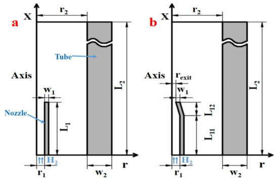
Figure 1.
The schematic diagrams of physical models: (a) d = 0.8 mm; (b) d = 0.4 mm.
2.2. Mathematical Model
The diameters of the nozzles used in this study are larger than the mean free path of hydrogen gas (0.0002 mm). Correspondingly, the Knudsen number (0.00025) was lower than its critical value (0.001). Thereby, the hydrogen stream was considered continuous, and N-S equations were adopted [45]. Since the largest Reynolds number at the inlet of nozzle was 401 (V = 55 m/s), the laminar flow model was selected. A 2D axisymmetric model was adopted for numerical simulation. Since the focus of this study was on combustion efficiency rather than near-limit flame dynamics, the steady state simulation was chosen, and the governing equations are given below for the fuel gas.
Mass conservation:
Momentum conservation:
Energy conservation:
Species conservation:
Equation of gas state:
Heat conduction within the nozzle and tube walls was taken into account in the modeling, as expressed in Equation (6).
In the above formulas, υ represents velocity vector, I denotes the unit tensor and J is a diffusive mass flux vector; T refers to temperature, p is pressure, ρ is density and R the universal gas constant; λ is thermal conductivity and μ is dynamic viscosity of gas. They were computed by applying the ideal gas mixing law. As for specific heat capacity of the mixture, cp, its value was an average based on each species’ mass fraction. Yi, hi, Mi and ωi, respectively, indicate the mass fraction, enthalpy, molecular weight and production rate of the ith component. They were obtained based on the kinetic theory [46]:
The diffusive mass flux vector, J, was calculated with the Maxwell–Stefan equation [47], where both full multicomponent diffusion and Soret diffusion are considered.
[D] is a matrix of diffusion coefficients [48], and Dij is the binary mass diffusion coefficient, which was computed through modified Enskog–Chapman formula [49]:
where Xi denotes the ith species’ mole fraction; Ω is the diffusion collision integral; σ is the reduced collision diameter; and DT,i was obtained from the empirical formula [50]:
2.3. Computation Scheme
The reaction kinetics reported in [51] were adopted to simulate H2–air combustion. The DO (discrete ordinates) model was applied for the calculation of surface-to-surface radiation. The boundary conditions of the system are explained below. At the inlet of the nozzle, uniform velocity and temperature (300 K) were set for the hydrogen stream. The inlet and outlet of the tube were specified as pressure boundaries. A symmetric boundary was given for the center line. The exterior tube wall was set to be a hybrid thermal boundary (natural convection + thermal radiation), and heat dissipation rate per unit surface area was computed by Equation (20).
Here, T∞ is the environmental temperature (300 K); Tw is outer wall temperature. h denotes the natural convection heat transfer coefficient (20 W·m−2·K−1); εw and σ represent surface emissivity (0.65) and the Stephan–Boltzmann constant (5.67 × 10⁻⁸ W·m−2·K−4), respectively. Ansys Fluent was employed to solve the discretized equations. A high temperature zone (1500 K) was set near the nozzle exit to trigger combustion reaction. The convergence criteria of mass, momentum, energy and species equations were set to be 10−8, 10−6, 10−8 and 10−3, respectively.
2.4. Grid Independence
We used non-uniform structural grids for mesh generation, and refinement was conducted in the flame region. Here, the grid independence was checked in Model A by using 25,000, 50,000 and 80,000 cells. The temperature profile along the center line at the jet velocity (Vf) of 15 m/s is plotted in Figure 2. It can be identified that the largest discrepancy between the three sets of grid systems was less than 3%. Hence, the grid system with 50,000 cells was employed for the following computations.
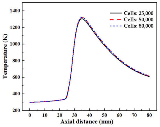
Figure 2.
Temperature profile along the center line obtained by three grid systems at Vf = 15 m/s for Model A.
2.5. Model Validation
To validate the current numerical scheme, Figure 3 [42,43,44] depicts numerical and experimental [33] results of flame height. The comparison demonstrates that the maximum relative error was less than 7.2%. Therefore, reasonable accuracy of the present numerical simulation could be expected.
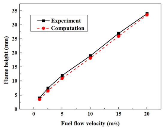
Figure 3.
Validation of the numerical results of flame height with experimental data [33].
3. Results and Analysis
3.1. Effects of Nozzle Diameter on Combustion Efficiency and Flammable Limits
In this work, the definition of combustion efficiency η is given below:
where min,H2 designates the incoming hydrogen mass flow rate, and mout,H2 is the residual hydrogen at the tube exit. The relationships between combustion efficiency η and jet velocity are illustrated in Figure 4 for the two nozzle exit diameters. It is shown that for d = 0.8 mm, the combustion efficiency increased gradually with jet velocity, and reached a maximum value of slightly higher than 15%. In contrast, for d = 0.4 mm, the combustion efficiency rose rapidly in the low fuel-velocity zone, and remained almost invariant at around 36% in the region of relatively high velocity. In addition, it can be seen that, compared to the straight nozzle, the lower and upper velocity limits both decreased due to the reduction of nozzle exit diameter (which doubled the jet velocity at the nozzle exit).
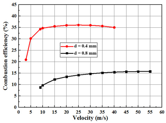
Figure 4.
The relationships between combustion efficiency and jet velocity for the two combustors with different nozzle exit diameters.
Figure 5 illustrates the contours of H2 and O2 mass fractions within the two combustors under the same fuel inlet velocity of Vf = 25 m/s. Obviously, when d = 0.4 mm, the hydrogen mass fraction remained far lower level compared to that of d = 0.8 mm. Meanwhile, the entrained oxygen was depleted later when d = 0.4 mm. Consequently, the combustion efficiency significantly increased as the nozzle exit diameter reduced.
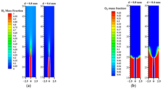
Figure 5.
Mass fraction contours of H2 and O2 within the two combustors under Vf = 25 m/s: (a) d = 0.8 mm, (b) d = 0.4 mm.
3.2. Analysis
In the following, the effects of nozzle exit diameter on combustion efficiency are analyzed by comparing the flame shapes and air entrainment abilities of these two combustors.
3.2.1. Impacts of Nozzle Exit Diameter on Flame Shape under Various Fuel Velocities
The mass fraction contours of OH were adopted to represent the reaction zone of a hydrogen flame. Figure 6 depicts the flame shapes (structures) resulting from various fuel velocities within the two combustors that had different nozzle exit diameters. First, it can be seen that with a low fuel velocity, the flame surrounds the nozzle wall at a location much lower than the nozzle exit. As the fuel velocity increases, the flame climbs upwards and surrounds the nozzle exit. Meanwhile, the flame is prolonged and the flare angle becomes smaller at higher fuel velocities. When comparing Figure 6b,f, and Figure 6c,g, it is clear that the for the same fuel inlet velocity, the flame length increased while the flare angle decreased in the case of d = 0.4 mm, which indicates that more fuel can be burned and a higher combustion efficiency can be achieved as the nozzle exit diameter is reduced. However, the combustion efficiency was still very low for d = 0.4 mm, since the flame tip remained open under all fuel inlet velocities, so a large amount of hydrogen would leak out without combustion.
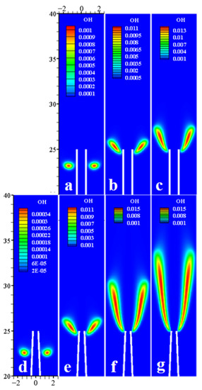
Figure 6.
Contours of OH mass fraction at various jet velocities: (a) d = 0.8 mm, Vf = 9 m/s; (b) d = 0.8 mm, Vf = 25 m/s; (c) d = 0.8 mm, Vf = 40 m/s; (d) d = 0.4 mm, Vf = 3 m/s; (e) d = 0.4 mm, Vf = 9 m/s; (f) d = 0.4 mm, Vf = 25 m/s; (g) d = 0.4 mm, Vf = 40 m/s.
Figure 7 presents the temperature variations of the flame (left vertical axis) and exhaust gas (right vertical axis) with jet velocity for the two combustors with different nozzle exit diameters. It is clear that for the same jet velocity, the flame temperature for the d = 0.4 mm system was much higher than that of the d = 0.8 mm system, especially for low fuel velocities. For example, at Vf = 9 m/s, the difference between the flame temperatures of these two combustors was larger than 800 K. On the other hand, the average exhaust gas temperature of the two combustors increased almost linearly with fuel velocity, but it rose up more rapidly under d = 0.4 mm. At Vf = 40 m/s, the difference in average exhaust gas temperatures between these two combustors exceeded 300 K. The reason why the largest difference of average exhaust gas temperature appeared at high fuel velocities is because the heat dissipation rate increases with the wall surface temperature, which rises with the flame temperature and ultimately fuel inlet velocity.
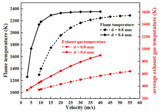
Figure 7.
Temperature variations of flame and exhaust gas with jet velocity.
3.2.2. Air Entrainment Ratio
Combustion efficiency depends significantly on the air entrainment ability of the fuel jet flow, which is reflected by the ratio of entrained air flow rate, mair, to the fuel flow rate, mfuel, as given below:
It is well known that the air entrainment ability depends on the pressure field in the combustor, which is a result of the velocity field. For the purpose of comparison, the axial velocity profiles of the two combustors under Vf = 25 m/s are plotted in Figure 8. Figure 9 depicts the pressure fields at the identical jet velocity. As can be seen, the fuel velocity started to increase from the nozzle inlet due to the preheating effect by the nozzle wall, which indicates the thermal interaction between the flame and nozzle wall. More specifically, from x = 0 to 20 mm, the axial velocity profiles of the two combustors almost overlap and the fuel jet velocity (x = 25 mm) for d = 0.8 mm was 61 m/s. However, the fuel velocity of d = 0.4 mm rose to 178 m/s due to the convergence of nozzle exit. As a result, the negative pressure level of the d = 0.4 mm system became far lower than that of the d = 0.8 mm system. To be specific, the lowest pressures for d = 0.4 and 0.8 mm systems were −14.7 pa and −4.2 pa, respectively. Therefore, the air entrainment ability of the fuel jet could be enhanced in the case of d = 0.4 mm.
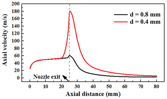
Figure 8.
Axial velocity profiles of the two combustors with different nozzle exit diameters at Vf = 25 m/s.
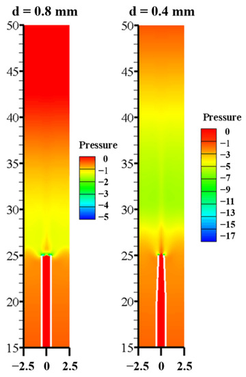
Figure 9.
A comparison between the pressure fields in the two combustors with different nozzle exit diameters at Vf = 25 m/s: (a) d = 0.8 mm and (b) d = 0.4 mm.
The changes in air entrainment ratio with jet velocity are shown in Figure 10 for the two combustors. It can be observed that the air entrainment ratio of the d = 0.8 mm system rose slowly with the jet velocity. The d = 0.4 mm system first had a rapid increase, and then remained at a value of around 12. These tendencies are similar to those demonstrated in Figure 4 for combustion efficiency. Furthermore, the air entrainment ratio of the d = 0.4 mm system is far greater than that of the d = 0.8 mm system. Consequently, the combustion efficiency of the d = 0.4 mm system is far higher. However, all the entrainment ratios of d = 0.4 mm are still far less than the critical value of 34.335 (under which complete combustion is possible). Thus, the maximum combustion efficiency of d = 0.4 mm is only 36% (Figure 4). This implies that other measures, such as expanding the tube diameter or further decreasing the nozzle exit diameter, should be adopted to further improve the combustion efficiency in our future studies.
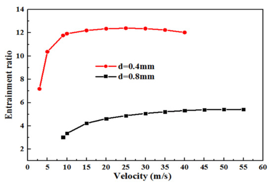
Figure 10.
Air entrainment ratio vs. jet velocity for the two combustors with different nozzle exit diameters.
4. Conclusions
In this study, the effects of nozzle exit diameter (d = 0.4 mm and 0.8 mm) on the combustion completeness of hydrogen microjet flames within a mesoscale tube without active air supply and without buoyancy effect were numerically investigated. Based on the comparison and analysis of the results, we obtained the following conclusions.
- (1)
- For the same jet velocity, greater combustion efficiency is obtained by a combustor with a smaller nozzle exit. The maximum combustion efficiency of a combustor with d = 0.8 mm is only around 15%, whereas the peak value for the case of d = 0.4 mm reaches around 36%.
- (2)
- With d = 0.4 mm, the fuel jet velocity is much higher than with d = 0.8 mm because the cross-sectional area of the nozzle exit is reduced to 1/4 of the original configuration. Hence, the negative pressure in a combustor with d = 0.4 mm can be decreased to a far lower level than that of a d = 0.8 mm system, which leads to an enhanced air entrainment ratio.
- (3)
- The highest combustion efficiency of d = 0.4 mm is still relatively low (36%); therefore, additional modifications, such as a slightly larger tube or an even smaller nozzle exit, will be necessary to further improve the combustion efficiency.
Author Contributions
Investigation, writing—original draft preparation, J.H.; methodology, software, M.Z.; project administration, L.L.; validation, Q.S.; writing—review and editing, X.X.; supervision, funding acquisition, A.F.; All authors have read and agreed to the published version of the manuscript.
Funding
The current work was funded by the Natural Science Foundation of China (NSFC) with a Grant Number of 51576084.
Institutional Review Board Statement
Not applicable.
Informed Consent Statement
Not applicable.
Data Availability Statement
Data is contained within the present article.
Conflicts of Interest
The authors declare no conflict of interest.
References
- Fernandez-Pello, A.C. Micropower generation using combustion: Issues and approaches. Proc. Combust. Inst. 2002, 29, 883–899. [Google Scholar] [CrossRef]
- Walther, D.C.; Ahn, J. Advances and challenges in the development of power generation systems at small scales. Prog. Energy Combust. Sci. 2011, 37, 583–610. [Google Scholar] [CrossRef]
- Ju, Y.; Maruta, K. Microscale combustion: Technology development and fundamental research. Prog. Energy Combust. Sci. 2011, 37, 669–715. [Google Scholar] [CrossRef]
- Maruta, K.; Kataoka, T.; Kim, N.I.; Minaev, S.; Fursenko, R. Characteristics of combustion in a narrow channel with a temperature gradient. Proc. Combust. Inst. 2005, 30, 2429–2436. [Google Scholar] [CrossRef]
- Fan, Y.; Suzuki, Y.; Kasagi, N. Quenching mechanism study of oscillating flame in micro channels using phase-locked OH-PLIF. Proc. Combust. Inst. 2011, 33, 3267–3273. [Google Scholar] [CrossRef]
- di Stazio, A.; Chauveau, C.; Dayma, G.; Dagaut, P. Combustion in micro-channels with a controlled temperature gradient. Exp. Therm. Fluid Sci. 2016, 73, 79–86. [Google Scholar] [CrossRef]
- Wang, S.X.; Fan, A.W. Combustion regimes of syngas flame in a micro flow reactor with controlled temperature profile: A numerical study. Combust. Flame 2021, 230, 111457. [Google Scholar] [CrossRef]
- Wan, J.L.; Fan, A.W. Recent progress in flame stabilization technologies for combustion-based micro energy and power systems. Fuel 2021, 286, 119391. [Google Scholar] [CrossRef]
- Ahn, J.; Eastwood, C.; Sitzki, L.; Ronney, P.D. Gas-phase and catalytic combustion in heat-recirculating burners. Proc. Combust. Inst. 2005, 30, 2463–2472. [Google Scholar] [CrossRef]
- Kim, N.I.; Kato, S.; Kataoka, T.; Yokomori, T.; Maruyama, S.; Fujimori, T.; Maruta, K. Flame stabilization and emission of small Swiss-roll combustors as heaters. Combust. Flame 2005, 141, 229–240. [Google Scholar] [CrossRef]
- Zhong, B.J.; Wang, J. Experimental study on premixed CH4/air mixture combustion in micro Swiss-roll combustors. Combust. Flame 2010, 157, 2222–2229. [Google Scholar] [CrossRef]
- Vijayan, V.; Gupta, A.K. Flame dynamics of a meso-scale heat recirculating combustor. Appl. Energy 2010, 87, 3718–3728. [Google Scholar] [CrossRef]
- Tang, A.K.; Cai, T.; Deng, J.; Xu, Y.M.; Pan, J.F. Experimental investigation on combustion characteristics of premixed propane/air in a micro-planar heat recirculation combustor. Energy Convers. Manag. 2017, 152, 65–71. [Google Scholar] [CrossRef]
- Yan, Y.F.; Pan, W.L.; Zhang, L.; Tang, W.M.; Chen, Y.R.; Li, L.X. Numerical study of the geometrical parameters on CH4/air premixed combustion in heat recirculation micro-combustor. Fuel 2015, 159, 45–51. [Google Scholar] [CrossRef]
- Yang, W.M.; Chou, S.K.; Shu, C.; Li, Z.W.; Xue, H. Combustion in micro-cylindrical combustors with and without a backward facing step. Appl. Therm. Eng. 2002, 22, 1777–1787. [Google Scholar] [CrossRef]
- Wan, J.L.; Fan, A.W.; Maruta, K.; Yao, H.; Liu, W. Experimental and numerical investigation on combustion characteristics of premixed hydrogen/air flame in a micro-combustor with a bluff body. Int. J. Hydrogen Energy 2012, 37, 19190–19197. [Google Scholar] [CrossRef]
- Wan, J.L.; Yang, W.; Fan, A.W.; Liu, Y.; Yao, H.; Liu, W.; Du, Y.Q.; Zhao, D.Q. A numerical investigation on combustion characteristics of H2/air mixture in a microcombustor with wall cavities. Int. J. Hydrogen Energy 2014, 39, 8138–8146. [Google Scholar] [CrossRef]
- Wan, J.L.; Fan, A.W.; Liu, Y.; Yao, H.; Liu, W.; Gou, X.L.; Zhao, D.Q. Experimental investigation and numerical analysis on flame stabilization of CH4/air mixture in a mesoscale channel with wall cavities. Combust. Flame 2015, 162, 1035–1045. [Google Scholar] [CrossRef]
- Li, L.H.; Yuan, Z.L.; Xiang, Y.; Fan, A.W. Numerical investigation on mixing performance and diffusion combustion characteristics of H2 and air in planar micro-combustor. Int. J. Hydrogen Energy 2018, 43, 12491–12498. [Google Scholar] [CrossRef]
- Prakash, S.; Armijo, A.D.; Masel, R.I.; Shannon, M.A. Flame dynamics and structure within sub-millimeter combustors. AICHE J. 2010, 53, 1568–1577. [Google Scholar] [CrossRef]
- Ju, Y.; Xu, B. Studies on non-premixed flame streets in a mesoscale channel. Proc. Combust. Inst. 2009, 32, 1375–1382. [Google Scholar]
- Xiang, Y.; Yuan, Z.L.; Wang, S.X.; Fan, A.W. Effects of flow rate and fuel/air ratio on propagation behaviors of diffusion H2/air flames in a micro-combustor. Energy 2019, 179, 315–322. [Google Scholar] [CrossRef]
- Xiang, Y.; Zhao, M.; Huang, H.; Fan, A.W. Experimental investigation on the scale effects on diffusion H2/air flames in Y-shaped micro-combustors. Int. J. Hydrogen Energy 2019, 44, 30462–30471. [Google Scholar] [CrossRef]
- Xiang, Y.; Fan, A.W. A numerical study on diffusion H2/air flames in Y-shaped mesoscale combustors. Fuel 2020, 275, 117935. [Google Scholar] [CrossRef]
- Wang, S.X.; Yuan, Z.L.; Fan, A.W. Experimental investigation on non-premixed CH4/air combustion in a novelminiature Swiss-roll combustor. Chem. Eng. Process. 2019, 139, 44–50. [Google Scholar] [CrossRef]
- Ning, D.G.; Liu, Y.; Xiang, Y.; Fan, A.W. Experimental investigation on non-premixed methane/air combustion in Y-shaped meso-scale combustors with/without fibrous porous media. Energy Convers. Manag. 2017, 138, 22–29. [Google Scholar] [CrossRef]
- Li, L.H.; Wang, S.X.; Zhao, L.; Fan, A.W. A numerical investigation on non-premixed catalytic combustion of CH4/(O2+N2) in a planar micro-combustor. Fuel 2019, 255, 115823. [Google Scholar] [CrossRef]
- Jiaqiang, E.; Peng, Q.; Zhao, X.; Zuo, W.; Zhang, Z.; Pham, M. Numerical investigation on the combustion characteristics of non-premixed hydrogen-air in a novel micro-combustor. Appl. Therm. Eng. 2017, 110, 665–677. [Google Scholar]
- Matta, L.M.; Neumeier, Y.; Lemon, B.; Zinn, B.T. Characteristics of microscale diffusion flames. Proc. Combust. Inst. 2002, 29, 933–939. [Google Scholar] [CrossRef]
- Chen, C.P.; Chao, Y.C.; Cheng, T.S.; Chen, G.B.; Wu, C.Y. Structure and stabilization mechanism of a microjet methane diffusion flame near extinction. Proc. Combust. Inst. 2007, 31, 3301–3308. [Google Scholar] [CrossRef]
- Cheng, T.S.; Chen, C.P.; Chen, C.S.; Wu, C.Y.; Li, Y.H.; Chao, Y.C. Characteristics of microjet methane diffusion flames. Combust. Sci. Technol. 2006, 10, 861–881. [Google Scholar] [CrossRef]
- Cheng, T.S.; Chao, Y.C.; Wu, C.Y.; Li, Y.H.; Nakamura, Y.; Lee, K.Y.; Yuan, T.; Leu, T.S. Experimental and numerical investigation of microscale hydrogen diffusion flames. Proc. Combust. Inst. 2005, 30, 2489–2497. [Google Scholar] [CrossRef]
- Zhang, J.; Li, X.; Yang, H.L.; Jiang, L.Q.; Wang, X.H.; Zhao, D.Q. Study on the combustion characteristics of non-premixed hydrogen micro-jet flame and the thermal interaction with solid micro tube. Int. J. Hydrogen Energy 2017, 42, 3853–3862. [Google Scholar] [CrossRef]
- Gao, J.; Hossain, A.; Nakamura, Y. Flame base structures of micro-jet hydrogen/methane diffusion flames. Proc. Combust. Inst. 2017, 36, 4209–4216. [Google Scholar] [CrossRef]
- Hirasawa, T.; Sumi, M.; Nakamura, Y. Effect of burner size and material on extinction of methane diffusion microflame. J. JSME 2013, 13, 75–79. [Google Scholar]
- Fujiwara, K.; Nakamura, Y. Experimental study on the unique stability mechanism via miniaturization of jet diffusion flames (microflame) by utilizing preheated air system. Combust. Flame 2013, 160, 1373–1380. [Google Scholar] [CrossRef][Green Version]
- Hossain, A.; Nakamura, Y. Thermal and chemical structures formed in the micro burner of miniaturized hydrogen-air jet flames. Proc. Combust. Inst. 2015, 35, 3413–3420. [Google Scholar] [CrossRef]
- Li, X.; Zhang, J.; Yang, H.L.; Jiang, L.Q.; Wang, X.H.; Zhao, D.Q. Combustion characteristics of non-premixed methane micro-jet flame in coflow air and thermal interaction between flame and micro tube. Appl. Therm. Eng. 2017, 112, 296–303. [Google Scholar] [CrossRef]
- Ban, H.; Venkatesh, S.; Saito, K. Convection-diffusion controlled laminar micro flames. J. Heat Transfer 1994, 116, 954–959. [Google Scholar] [CrossRef]
- Sunderland, P.B.; Mendelson, B.J.; Yuan, Z.G.; Urban, D.L. Shapes of buoyant and nonbuoyant laminar jet diffusion flames. Combust. Flame 1999, 116, 376–386. [Google Scholar] [CrossRef]
- Zhang, D.; Fang, J.; Guan, J.F.; Wang, J.W.; Zeng, Y.; Wang, J.J.; Zhang, Y.M. Laminar jet methane/air diffusion flame shapes and radiation of low air velocity coflow in microgravity. Fuel 2014, 130, 25–33. [Google Scholar] [CrossRef]
- Liu, L.; Zhao, M.; Chen, Y.K.; Fan, A.W.; Li, D. A numerical investigation in the buoyancy effects on micro jet diffusion flame. J. Cent. South Univ. 2020, 27, 867–875. [Google Scholar] [CrossRef]
- Zhao, M.; Fan, A.W. Buoyancy effects on hydrogen diffusion flames confined in a small tube. Int. J. Hydrogen Energy 2020, 45, 19926–19935. [Google Scholar] [CrossRef]
- Zhao, M.; Liu, L.; Fan, A.W. Comparison of combustion efficiency of micro hydrogen jet flames confined in cylindrical tubes of different diameters. Chem. Eng. Process 2020, 153, 108000. [Google Scholar] [CrossRef]
- Beskok, A.; Karniadakis, G.E. A model for flows in channels, pipes, and ducts at micro and nano scales. Manosc. Microsc. Therm. 1999, 3, 43–77. [Google Scholar]
- Zhai, X.; Ding, S.; Cheng, Y.; Jin, Y.; Cheng, Y. CFD simulation with detailed chemistry of steam reforming of methane for hydrogen production in an integrated micro-reactor. Int. J. Hydrogen Energy 2010, 35, 5383–5392. [Google Scholar] [CrossRef]
- Merk, H.J. The macroscopic equations for simultaneous heat and mass transfer in isotropic, continuous and closed systems. Appl. Sci. Res. 1959, 8, 73–99. [Google Scholar] [CrossRef]
- Taylor, R.; Krishna, R. Multicomponent Mass Transfer; Wiley: New York, NY, USA, 1993. [Google Scholar]
- McGee, H.A. Molecular Engineering; McGraw-Hill: New York, NY, USA, 1991. [Google Scholar]
- Kuo, K.K.Y. Principles of Combustion; John Wiley and Sons: New York, NY, USA, 1986. [Google Scholar]
- Li, J.; Zhao, Z.W.; Kazakov, A.; Dryer, F.L. An updated comprehensive kinetic model of hydrogen combustion. Int. J. Chem. Kinet. 2004, 36, 566–575. [Google Scholar] [CrossRef]
Publisher’s Note: MDPI stays neutral with regard to jurisdictional claims in published maps and institutional affiliations. |
© 2021 by the authors. Licensee MDPI, Basel, Switzerland. This article is an open access article distributed under the terms and conditions of the Creative Commons Attribution (CC BY) license (https://creativecommons.org/licenses/by/4.0/).