Abstract
Multi-phase motors and generators are regarded with great fault tolerance capability, especially on open-circuit faults. Various mathematics analytical methods are applied for their fault control. In this paper, a fault-tolerant control strategy with asymmetric phase current for the open-circuit faults with arbitrary phases in the six-phase PMSM (six-phase permanent magnetic synchronous motor, 6P-PMSM) system, is proposed for better electrical and dynamical performance of the machine. An innovative mathematical model for PMSM under one to four-phase-open circuit faults are established considering the asymmetry of the machine. Combining with time-varying relations in machines’ working conditions, targeted decoupling transformation matrixes of every kind of open-circuit faults are settled by voltage equations under different faults. Modified control strategy with a connection between the neutral point and the inverter’s DC side is presented, which aims at increasing the system redundancy and reducing the amplitude of phase currents. Besides, improved control loops with two layers are put forward as well, with which the PMSM system acquires fewer harmonics in phase current and smoother electromagnetic torque. Simulation and experimental results of open-circuit faults are provided for verification of the theoretical analysis.
1. Introduction
With the development of power electronics, high power facilities have been regarded as the trend of electric drive and generator. Multi-phase motors thus are getting more and more attention [1,2]. Dual three-phase PMSM have more strengths of multi-phase electrical machines, including high power density, low torque fluctuation, improved fault tolerance and increased control objects as compared to other multi-phase electrical machines [3]. Among these advantages, improving fault tolerance is of great significance in terms of operation safety and power quality [4] of PMSM. To increase the reliability under one or several phases, open-circuit faults, innovations on system structure and control strategies are becoming new research trends [5,6,7,8,9,10].
In terms of multi-phase electrical machines, redundancy allows more types of faults happening [11]. Redundancy of PMSM is always realized by increasing windings or adopting the inverter with more switches combination which provides more control modes [12,13,14]. Except for reforms on windings and switch numbers, improvements of the machine structure are mainly aimed at two aspects. Changing the stator structure and winding distribution limits the short-circuit current and decreases the damage of circuit faults [12,15]. Optimizing the quantity and distribution of the slot changes the lumped parameters of the stator, while minimizes the mutual inductance and raises the independence of each phase [3].
Many novel control strategies are proposed for the fault tolerance of PM (permanent magnetic) machines. For open-circuit faults, the vanished currents in the open phases are expected to be rectified by the survived phase currents. New amplitudes and phases of the currents are settled with the undetermined coefficient method and other correlative algorithms [16,17,18,19,20,21]. Alternatively, with decoupling transformation, currents are transferred to field-oriented and field-orthogonal directions [22,23] and reshaped according to the dynamic and electromagnetic performance [24,25]. Common shortages of these control strategies are harmonics and torque ripples generated by the machine asymmetry under faults, which reflects the conflicts between the complex condition of the machine and the simplification of the analysis model.
This paper mainly focuses on control strategies innovation. Considering the asymmetric working condition of the machines under open-circuit faults, some time-varying contents could be added into the mathematical model of the PM machines, which will increase the flexibility and accuracy of the fault-tolerant control. Besides, an improvement on the decoupling method could help the torque, power, and to be controlled more independently, which could be realized by adjustment of transformation matrixes and current loop structure.
In this paper, a novel fault-tolerant control strategy is introduced, which takes account of model simplification and control effects. Based on the optimal phase current solutions under one to four-phase open-circuit faults, decoupling transformation matrixes from every phase to static and rotating coordinates are recalculated and reselected. Meanwhile, a subsystem for harmonics suppression is established. Modifications in the current loop structure have been proposed by taking into consideration the periodic asymmetry of the machine under faults. A simulation model with MATLAB/Simulink and experimental platform are built separately for proving that the proposed fault-tolerant control strategy can response to the open faults in any number of phases under four in 6P-PMSM.
2. Fault-Tolerant Control Strategy Related to Zero Sequence Current
The structure diagram of the dual three-phase PMSM is shown as Figure 1. The dual three-phase PMSM has two groups of symmetrical windings a, c, e and b, d, f. The phase to phase electric angle of each group is 120° and between two groups there is an electric angle of 30°.
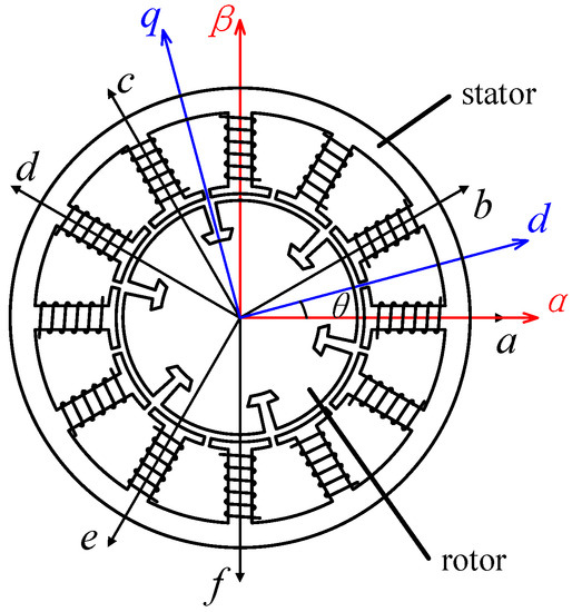
Figure 1.
Structure of dual three-phase PMSM.
The dual three-phase PMSM is actually a complete set of six-phase permanent magnet synchronous motor (6P-PMSM) system. More advantages of 6P-PMSM can be achieved by using fault-tolerant control and optimizing the connection of neutral points.
The two neutral points have three connection patterns. First, with both insulated neutral points, the sum of phase currents in each group should be zero. Second, with connected neutral points but insulated from ground, the sum of all the six phase currents should be zero. Finally, with neutral points both connected to the ground, no current restrictions need to be satisfied by the phase currents. The looser the current restrictions are, the more freedom degrees are generated, which is significant for multi-phase open fault-tolerant control. The neutral points insulating system can only tolerate a single-phase open fault. The neutral points connecting system can tolerate one to three-phase open faults. Further, the system with both neutral points connected to the ground can tolerate one to four phases open faults.
Equations of the phase voltages could be written as follows:
where u is the column matrix of the phase voltage uk (k includes a, b, c, d, e, f), ψ is the column matrix of the stator flux ψk. Further, Rs is the winding resistance, i is the phase current matrix. The component ψk of ψ can be expressed as:
where ψr is the maximum flux between stator phase winding and rotor pole, θ is the electric angle of the rotor. Therefore, αk is the angle between every phase and Phase a. Lkp is the component of the PMSM phase inductance matrix Ls, which is the inductance between two phases. k and p represent the name of the specific phase including a, b, c, d, e, f. If Lkp is self-inductance, k and p are the same. The phase inductance can be expressed as:
where Ll is the leakage inductance, Lm is the coefficient of the constant part of inductance between the stator windings, which is solid as rotor moves. La is the coefficient of periodically changing part of inductance between stator windings, which is influenced by the rotor position.
Under normal operation of PMSM, all the phase voltages are of the same amplitude with each other and in the same relative phase position as the corresponding currents. Relative physical quantities, including the resistance, flux, and inductance are also part of spatial symmetry of the phases. Once one or several phase currents vanish, the spatial symmetry is destroyed, which leads to asymmetry among the phase currents and the physical quantities. Any periodic change in these quantities reflects their time-varying characteristics, which are originally balanced.
When there is no fault in 6P-PMSM system, the magnetic potential is provided by the symmetrical current. Therefore, there are two equations among the phase currents.
When open circuit faults happen in stator windings, the corresponding ik will be 0, and the remaining phase currents will no longer be symmetrical. However, the magnetic potential they produce should be invariant. No matter how many phase currents are 0, (4) exists as long as the PMSM can still work.
According to the existing literature and analysis methods, the open-circuit faults and control strategies of PMSM are based on the research when the motor is running from normal state to fault state. Further, combined with various electrical parameters of generator’s fault state, the fault-tolerant control strategy is studied.
The fault types and corresponding treatment methods about the system of six-phase PMSM and inverter are summarized in Table 1.

Table 1.
Corresponding Treatment Methods about the System of 6P-PMS and Inverter.
This paper focuses on the fault-tolerant control of PMSM. The corresponding of fault-tolerant control strategy is introduced below.
2.1. Tolerant Control under Single-Phase-Open Fault
Single-phase-open circuit fault of any phase can be converted to the case of Phase f open with primary transformation, so the case of Phase f open can be taken as the example. If Phase f is open, stator currents of Phase f will be 0. For 6P-PMSM, the two groups of phases can either work separately as a three-phase motor. Therefore, if possible, the current should satisfy the condition of balancing respectively in the group:
Besides, the copper loss minimization can be taken into consideration with the smallest heat power in the inner resistance of the stator:
Combining (4)–(6), phase currents under open-circuit fault can be solved with the Lagrange multiplier method, which can be written as:
Column vector i includes the phase current solution of Phases a to f in order. Further, C2s/6s is the transfer matrix from the static coordinate to the six phase directions.
For invariant magnetic potential, the currents on the α and β axis are expected to be unchanged as 3Icos θ and 3Isin θ. Therefore, the static coordinate transfer matrix C6s/2s under open-circuit faults should be the triple pseudo-inverse matrix of C2s/6s in (7). The d-q transfer matrix C6s/2r can be calculated with C6s/2s, which can project the currents and voltages in the six phases to the rotating coordinate axes:
Then the asymmetrical voltage equation under one-phase open circuit can be acquired with (1) and (2):
where Ld and Lq are the inductance on id and iq. Then, Ld can be expressed as (3 Lm + 3 La), while Lq can be expressed as (3 Lm − 3 La). Matrix X is the special coefficient matrix, which is variant with different open circuit fault situations, which is expressed as:
where C2r/6s is the pseudo inverse matrix of C6s/2r.
Matrix X is generated by the asymmetrical inductance caused by the asymmetrical phase currents under fault. When the PMSM is running in normal mode, X is a second-order identity matrix. Normally, the inner resistance Rs and leakage inductance Ll are small which can be ignored, so matrix X will be the common component in every left monomial. Under any open-circuit faults from one to four phases, the phase voltage equation has almost the same formations with (9). Matrix X represents similar structure for all kinds of open circuit faults, which can be expressed as:
where x1, x2, and δ are the characteristic parameters of X. For example, x1, x2, and δ of a motor in normal running mode are 0, 1 and 0, while under single-phase open fault they are 0.25, 0.75 and 0.
The electromagnetic torque equation under open-circuit faults is:
where p is the pole pair number of the PMSM.
When the stator windings are open, the torque of the PMSM will not change if the iq keeps stable. According to the above analysis, the control strategy for the open-circuit fault PMSM system is shown in Figure 2.
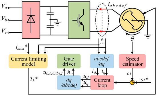
Figure 2.
Dual three-phase PMSM system.
As can be seen in (7), some new reference values of phase currents grow sharply, which will cause the amplitude of the corresponding phase currents largely increasing under the fault tolerant control. Therefore, when the open fault happens, the output torque and the rotating speed should be reduced to limit the phase currents under the system threshold within a short period.
Considering the actual operation, when the open-circuit fault happens in the system, the corresponding fault tolerant control is applied until the system is stopped. Even if the open fault can be recovered, the system should be stopped before the maintenance and inspection are adopted. Therefore, no resuming operation, which can alternate the fault tolerant control strategies to decrease the open phases, is introduced in the paper.
2.2. Tolerant Control under Two-Phase-Open Fault
The resulting asymmetry caused by two-phase-open circuit fault can be classified according to relative position of open phases. Cases of two open phases with the same angle values can be converted into each other with primary transformation. For example, the case of Phases e and f open is different from Phases d and f open. However, the case of Phases e and f open is similar to Phases c and d open.
Taking the case of Phase e and f open as an example, stator currents of Phase e and f will be zero. Although current restrictions can be set separately in the two groups of phases, if the two open phases are in one group, the last phase in the group will be zero naturally. Therefore, for two-phase-open fault, the current restriction should be the sum of currents in all the last four phases, which is zero.
Combining (4), (6) and (13), phase currents under Phases e and f open fault can be solved with the Lagrange multiplier method.
Static and rotating coordinate transfer matrixes under the open circuit fault can be solved with the same method with single-phase open case. All the phase current results and transfer matrixes C2s/6s under two-phase open case have the same form with (7). Therefore, the voltage equations in the d-q frame are the same as (9). Matrix X owns the structure as (11). Values of C2s/6s and the matrix X of all the possible open-phase relative positions are revealed in Table 2. With the specific parameters in Table 1, tolerant control under open faults with any two phases can be achieved in the PMSM system in Figure 2.
Table 2.
Optimum Solutions of Phase Currents and Parameters of Matrix X Under Two-Phase-Open Fault.
With the reason that the fault cases with the same angle between open phases can be converted mutually with primary transformation, one case with every angle value is taken as the example.
2.3. Tolerant Control under Three-Phase-Open Fault
Three-phase open circuit faults can also be classified by the relative position of open phases. Cases of the three open phases with the same mutual angles which can be converted into each other with primary transformation possess the same tolerant control strategy. For example, the case of Phases c, e, and f open is the same with Phases b, e and f open, and is different from a, e and f open.
If the current restriction exists, it should be (13). Compared with two-phase open cases, the three-phase open cases have one less degree of freedom, so the copper loss minimization condition (6) is not considered.
Static and rotating coordinate transfer matrixes under the open circuit fault can be solved with the same method with one-phase open cases. All the phase current results and transfer matrixes C2s/6s under three-phase open cases have the same form with (7). Therefore, the voltage equations in the d-q frame are the same as (9). Matrix X which depends on the transfer matrixes is different in each fault cases.
The corresponding C2s/6s and the matrix X of all the possible open-phase relative positions are shown in Table 3. One case with each kind of relative positions among the three angles is taken as the example, and cases with the same relative positions can be calculated by the primary transformation. With the specific parameters in Table 3, tolerant control under any three phases can be achieved in the PMSM system in Figure 2.
Table 3.
Optimum Solutions of Phase Currents and Parameters of Matrix X Under Three-Phase-Open Fault.
The above control strategy under three-phase open circuit faults is out of consideration of copper loss minimization to achieve the phase current balance in PMSM. However, it will cause large currents in PMSM much over the requirement of smooth operation at the original speed. If there is no current restriction in PMSM, the amplitude of phase current will be substantially reduced, which is beneficial to motor components and operation safety.
For this purpose, a connection between the PMSM neutral point and voltage midpoint of converter’s DC side is added for current injected into the neutral point of PMSM as shown in Figure 3.
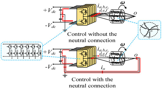
Figure 3.
The connection between the PMSM neutral point and voltage midpoint of converter’s DC side.
Figure 4 illustrates inverter functionality while two back to back IGBT’s are connected in series in each leg in order to isolate open circuit fault either its fault of single IGBT or fault of phase leg. Further, Sa1, Sa2, Sb1, Sb2, Sc1, Sc2, Sd1, Sd2, Se1, Se2, Sf1, Sf2 are the IGBT. Then, the a1, a2, b1, b2, c1, c2, d1, d2, e1, e2, f1, f2 are the switch. For example, when there is Phase-A-open fault of converter (open circuit faults because of the IGBT’s fault or short circuit faults on account of the IGBT’s fault), the Switches a1 and a2 of Phase A will be turned off and Phase A will be isolated. For other phase cases, the switching method is the same as above.
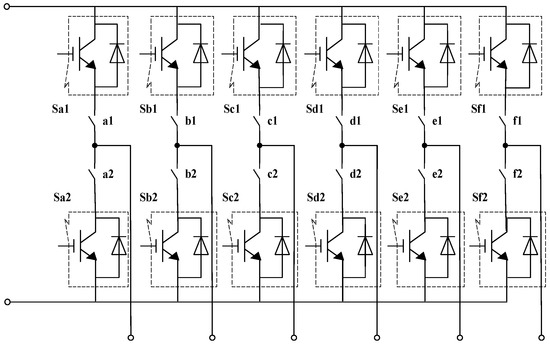
Figure 4.
The topology of six-phase converter with isolation function.
Then, even if the sum of phase currents in PMSM does not equal zero, the supplementary current will flow into PMSM through the connection and phase currents do not need to satisfy any restrictions.
To obtain the unique solutions of phase currents, the copper loss minimization target (6) is required, which helps to get the optimal phase current solution with a much smaller amplitude. Detailed values of C2s/6s and matrix X of all the possible open-phase relative positions are shown in Table 4. The coefficient matrix C2s/6s reflects the amplitude and direction of the phase current vectors with fault-tolerant control. Compared with the matrix C2s/6s in Table 3, values of coefficients in Table 4 is much smaller, which means that the phase currents would be reduced apparently with neutral point current. It would protect PMSM from overheat and resulting problems. Table 5 reflects the per-unit maximum phase current under three-phase-open fault applied the control strategies with and without neutral point current. Their quotients are the facility redundancy ratios caused by replacing the strategy without neutral point current. Further, the quotients of matrix C2s/6s square sum are the copper loss ratios. Yet, a large current in the neutral point wire is generated to complement the unbalancing phase currents, which is another source of conductor loss in the system.
Table 4.
Optimum Solutions of Phase Currents and Parameters of Matrix X Under Three-Phase-Open Fault with Neutral Point Current.
Table 5.
Per-Unit Maximum Phase Current under Different Three-Phase-Open Fault-Tolerant Control Strategies; the Redundancy and Copper Loss Ratios.
2.4. Tolerant Control under Four-Phase-Open Fault
When there are four phases open in the PMSM, only two phases are on work. To meet the requirement of maintaining magnetic potential, neither current restrictions nor minimum copper loss optimization is needed for the current solution.
Besides, similarly to the two-phase-open fault, all the cases of two phases with a certain angle on running can be converted into each other with primary transformation.
Static and rotating coordinate transfer matrixes can be solved with the same method as one-phase open cases. The voltage equations in the d-q frame are also as same as (9). The connection modes for the open-fault solutions are summarized in Table 6. With the specific parameters in Table 7, tolerant control under any three phases can be achieved in the PMSM system in Figure 2.
Table 6.
The Connection Modes for the Open-Fault Solutions.
Table 7.
Optimum Solutions of Phase Currents and Parameters of Matrix X Under Four-Phase-Open Fault with Neutral Point Current.
By the above purposed fault tolerant control strategy and taking into consideration the less copper losses due to current restrictions, connection modes for single phase to four phase open fault are summarized in Table 6.
3. Subspace for Harmonics Suppression
With the decentralized distribution of windings, there are always fifth, seventh and harmonics with other times in the phase currents. To eliminate these harmonics, the subspace aimed at separating and suppressing them is established. Harmonics should meet several conditions: (1) They exist in all the phases except the open ones. (2) The time integrals of them on the d-q axes are 0. (3) They satisfy the current restrictions of the PMSM system. Therefore, if the vector Z representing the subspace which contains six components is created, combining the three conditions, the elements in the column of open phases are 0. Besides, vector Z should be orthogonal to the matrix C2s/6s:
The subspace should also meet the corresponding current restriction to the kind of fault, including (5) and (13). The restriction of the vector length is added in place of the copper loss minimization condition (6):
where S is the length value which should be near the values of all the rows of the static coordinate transfer matrix. Cases of three phases open are divided by different control strategies. Under the control strategy with the neutral point current, (15) is also needed. While, under control strategy without the neutral point current, the unique solution of the matrix Z is zero vector. When a four-phase open fault happens, the solution of elements in the matrix is nonexistent. Therefore, in these cases, the subspace can be canceled. With the above conditions, vector Z of any possible open circuit fault type can be confirmed. Values of matrix Z under one and two-phase-open fault and the three-phase-open fault with neutral point current are shown in Table 8.
Table 8.
Matrix Z under One to Three-Phase-Open Fault Cases.
According to the above analysis, the tolerant control strategy with harmonics elimination is shown in Figure 5. Z+ is the pseudo-inverse matrix of Z. The part in the red box is applied with traditional PI control, which will be introduced in the next Section 4 in detail.
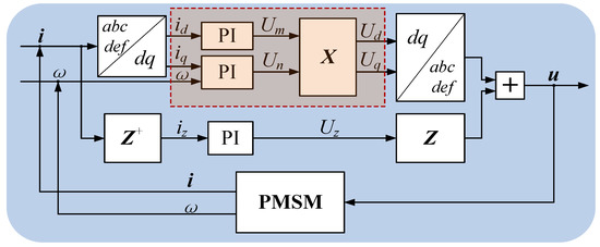
Figure 5.
Tolerant control strategy with harmonics elimination.
4. Dual Current Loops for Deeping Decoupling
For the traditional current control, two current loops are set for id and iq separately. According to the voltage equations in (9), the current control diagram under multi-phase open circuit fault should be as Figure 6.
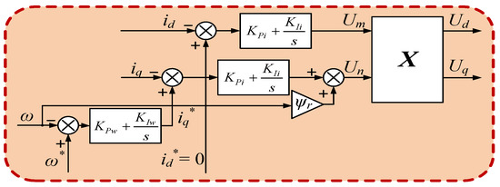
Figure 6.
Traditional current control.
The control strategy in Figure 6 ignores the monomials which contain Rs and Ll. Therefore, the equations are always incompletely decoupled and the torque current iq is unstable which makes the electromagnetic torque unable to balance the load torque all the time. It reflects in that the rotating speed, as well as id and iq fluctuate in a non-negligible range.
To eliminate the bad influences caused by the incomplete decoupling, an improved strategy for more complete decoupling of the current equations is designed as shown in Figure 7.
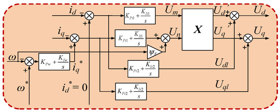
Figure 7.
Dual current loops control.
Instead of decoupling the whole voltages with matrix X, the new strategy divides the voltages Ud, Uq, and Uz into the time-varying part and the time-invariant part, which correspond to the monomials with X and the monomials without X in (9). For the values of these two parts are independent, the parameters in different layers of PI controllers should be linear independent, which makes the outputs of the inner and outer layers the unique solutions corresponding to the time-varying and time-invariant parts of the d-q voltages.
The improved strategy sets two layers in the current loops, which could be called dual current loops. Taking id as an example, the inner loop that acquires Um is multiplied with the time-varying matrix X, and the outer loop that acquires the voltage Udl is added directly to the output of the inner loop. The sum of the two parts is much closer to the accurate value of Ud than that from the traditional current loop.
Taken the difference between the real value and reference value of the electrical speed as the system output, and the load torque as the input, the block diagram could be simplified into Figure 8. G1(s), G2(s) and G3(s) are the simplified transfer functions which are relevant to the parameters of PMSM. Thus, the open-loop transfer function of the PMSM system could be expressed as:
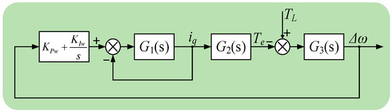
Figure 8.
The transfer function of rotating speed.
If the control strategy in Figure 6 is applied, with parameters in Table 8, the root locus is shown in Figure 9a, which moves by the change of the phase leakage inductance Ll.
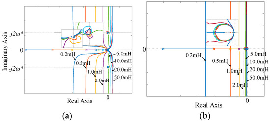
Figure 9.
Root locus. (a) Traditional current control. (b) Dual current loops control.
If the control strategy in Figure 7 is applied, G1(s) for the time-varying and time-invariant parts are different. For the time-varying part, it is expressed as G11(s) while for the time-invariant part is G12(s).
For the time-varying part, the roots are independent of Ll so it is always stable. For the time-invariant part, the roots move by the change of Ll which is shown in Figure 9b.
As can be seen in Figure 9, when the phase leakage inductance Ll increases and exceeds a specific value, the system tends to be unstable. Even if the Ll is small, root locus has some circles and discrete poles around the second harmonic points (0, ±j2ω*) on the imaginary axis, which means there will be a rotating speed fluctuation at 2ω* without attenuation no matter how small the phase leakage inductance is. Comparatively, the dual current loops control is much improved. By increasing Ll, all root locus is at the left of the imaginary axis, which means the system is always stable. Additionally, there are no pole points on the imaginary axis, which means the speed fluctuations can be eliminated with proper control parameters.
5. Simulation and Experimental Results
To verify the effectiveness of the fault-tolerance control for multiphase open circuit, simulation and experimental studies are carried out. Table 9 shows the simulation parameters of the PMSM system shown in Figure 2.
Table 9.
Parameters of Simulation.
Figure 10 shows the waveforms of phase currents, d-q currents, speed and electromagnetic torque in different faults and situations. The transfer time is 1.0 s. Figure 10a–d is from normal operation to four-phase open-circuit faults which are controlled with dual current control. Figure 10e is the waveforms from two-phase to three-phase open-circuit fault with traditional current loop control, which displays the comparison of waveforms with the two kinds of current control introduced in Section 4. Figure 10f displays the moment of changing control strategy from the one without neutral point current to the one with neutral point current under the three-phase open-circuit fault.
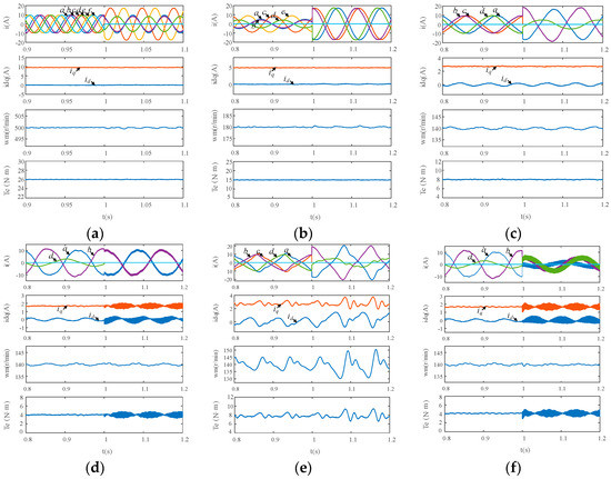
Figure 10.
Simulation results. (a) From normal operation to Phase f open fault with dual current loops control. (b) From Phase f open to Phases e, f open fault with dual current loops control. (c) From Phases e, f open to Phases c, e, f open fault with dual current loops control. (d) From Phases c, e, f open fault without neutral point current to Phases c, d, e, f open fault with dual current loops control. (e) From Phases e, f open to Phases c, e, f open fault with traditional current control. (f) Phases c, e, f open fault from “no-neutral-current strategy” to “neutral-current strategy” with dual current loops control.
According to Figure 10, when the number of open phase increases, with the tolerant control, phase currents changes in terms of amplitude and phase position, maximum of phase currents rises for providing the same torque with one phase less, rotating speed fluctuation grows with the reason that asymmetry of the PMSM is aggravated. Compared with the traditional current control, phase currents have much fewer harmonics and approach to sine waves, and the torque fluctuation is suppressed apparently.
The neutral point current is taken into the system when the four-phase open fault-tolerant control or the special three-phase open fault-tolerant control starts. However, when there is a neutral point current in the system, harmonics of high frequency in phase currents increase within a little scale. That is because the inductance of PMSM loses the current filtering effect of neutral point current part whose high-frequency contents are generated by the inverters. Generally, control effects reflected in the simulation results achieve the desired targets and coincide with the theoretical analysis.
Taken Phases c, e, f open fault with no neutral point current as an example, harmonics analysis of Phase a current is shown as Figure 11. The picture above is under traditional current control while the below is under dual current loops control. With the dual current loops control, the third, fifth and seventh harmonics are suppressed apparently, and the total harmonics distortion (THD) are decreased from 15.02% to 2.80%, which verifies the effectiveness of the current control.
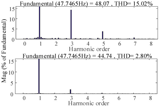
Figure 11.
Harmonics analysis of phase a current under the two kinds of current control.
An experimental platform is designed as shown in Figure 12.
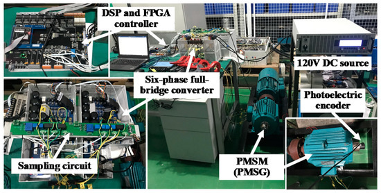
Figure 12.
The PMSM experimental system.
The 6P-PMSM with three pole pairs are connected to another same PMSM, which works as a generator with three power resistors of 10 Ω as the load. Two three-phase inverters are controlled by the digital controller of TMS320F28335 DSP. The experimental system is charged by a 340 V DC source which can provide the power of 3.4 kW at most. Combining the power of the DC source and the PMSM, electric speed reference of the PMSM are set as 500 r/min.
The phase currents and the corresponding id and iq under the one to four-phase open fault with dual current loops control in Figure 7 are shown in Figure 13. The phase currents of PMSM are almost the same as the relative phase position and amplitude in simulation results. Small differences between the experiment and simulation results are caused by the inevitable measurement errors of rotor position and deviation between the mathematical model and the experimental facility.
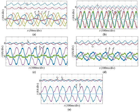
Figure 13.
Experimental results under dual current loops control: (a) Phase f open fault. (b) Phases e and f open fault. (c) Phases c, e and f open fault without neutral point current. (d) Phases c, e and f open fault with neutral point current. (e) Phases c, d, e and f open fault.
When the PMSM works as 500 r/min, the normal phase currents are about 5.6 A. Hence, to protect the facility, the maximum phase current under different fault cases is limited to 8.5 A. According to the analysis in Section 5, maximum of phase currents rises for providing the same torque with the phases less, so with the fixed phase current limit, the output torque of the PMSM decreases as the working phases reduce. According to (11), the torque is proportional to iq, so iq decreases as well. Figure 13c,d are the experimental results under three-phase open fault with the different control strategies. Figure 13c is without the neutral point current and Figure 13d is with the neutral point current, which outputs the same torque. As can be seen, the amplitude of phase currents in Figure 13d is much smaller than that in Figure 13c, which proves the reduction effect on the phase currents of the strategy with neutral point current. Figure 13e is the waveforms under four-phase open fault with the neutral point current. Compared with the three-phase open fault with the neutral point current, the amplitude of phase currents increases, which proves the analysis and the simulation result as well.
The distortions in the phase currents and the fluctuations in id and iq are mainly caused by the saliency of the motor poles. The theoretical analysis is based on the condition of the non-salient PMSM system. Therefore, according to (9), the coefficients of the differential term in ud and uq are the same, which decides the PI parameters of id and iq are the same. However, the PMSM in the experiment is with the salient poles, which will cause the fluctuations in id and iq as well as the distortions in the phase currents. These phenomena can be relieved by applying the PMSM with less saliency or adapting the PI parameters according to the specific Ld and Lq of the experimental PMSM.
Figure 14 shows the experimental results of Phases c, e and f open fault under two kinds of control, where Figure 14a is using dual current loops control and Figure 14b is using traditional current control. We can see that the speed is more stable under dual current loops control.
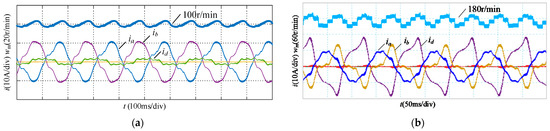
Figure 14.
Experimental results of Phases c, e and f open fault under two kinds of control: (a) Dual current loops control. (b) Traditional current control.
6. Conclusions
In this paper, tolerant control strategies under one to four phases open circuit faults in a 6P-PMSM system are proposed. To maintain the output torque stable, the optimal solution of phase currents under different faults are found, which are changed in both amplitude and phase position. Matrix X representing the asymmetry of the PMSM under all kinds of one to four-phase open circuit faults are calculated, which improves the decoupling and current loop control. Besides, to solve the problem of incomplete decoupling caused by stator resistance and leakage inductance, dual current loops control is proposed. By stability analysis, the innovative control strategy is proved to realize more complete decoupling and increase system reliability. With the series of tolerant control strategies, PMSM can output stable electromagnetic torque and phase current with little THD under one to three-phase-open faults without connection and four-phase open with the connection between the neutral point of PMSM and the midpoint of the inverter’s DC side. Simulation and experiment are built which can not only verify better fault tolerant control strategy to realize the high-performance control of PMSM, but also achieve motor’s smooth operation for single to four phases open circuit faults in asymmetric operation state.
In the future, due to the small amount of calculation and strong practicability, the control method can be widely used in the driving system of aerospace related equipment, large-capacity offshore wind power generation in the field of energy, EMU motors in the field of transportation, ship driving system and other aspects.
Author Contributions
Conceptualization, C.H.; methodology, L.Z.; formal analysis, Z.C.; investigation, G.Y. All authors have read and agreed to the published version of the manuscript.
Funding
This work was supported by the National Natural Science Foundation of China (NSFC) under Grant 52077135, and Shanghai Natural Science Foundation (SNSF) under Grant 18ZR1418400.
Institutional Review Board Statement
Not applicable.
Informed Consent Statement
Not applicable.
Data Availability Statement
Data sharing not applicable.
Conflicts of Interest
The authors declare no conflict of interest.
References
- Levi, E. Multiphase Electric Machines for Variable-Speed Applications. IEEE Trans. Ind. Electron. 2008, 55, 1893–1909. [Google Scholar] [CrossRef]
- Levi, E. Advances in Converter Control and Innovative Exploitation of Additional Degrees of Freedom for Multiphase Machines. IEEE Trans. Ind. Electron. 2016, 63, 433–448. [Google Scholar] [CrossRef]
- Cao, W.; Mecrow, B.C.; Atkinson, G.J.; Bennett, J.W.; Atkinson, D.J. Overview of Electric Motor Technologies Used for More Electric Aircraft (MEA). IEEE Trans. Ind. Electron. 2012, 59, 3523–3531. [Google Scholar]
- Jin, N.; Hu, S.; Gan, C.; Ling, Z. Finite States Model Predictive Control for Fault Tolerant Operation of Three-Phase Bidirectional AC/DC Converter Under Unbalanced Grid Voltages. IEEE Trans. Ind. Electron. 2017, 65, 819–829. [Google Scholar] [CrossRef]
- Chen, Q.; Liu, G.; Zhao, W.; Sun, L.; Shao, M.; Liu, Z. Design and Comparison of Two Fault-Tolerant Interior-Permanent-Magnet Motors. IEEE Trans. Ind. Electron. 2014, 61, 6615–6623. [Google Scholar] [CrossRef]
- Mecrow, B.C.; Jack, A.G.; Atkinson, D.J.; Green, S.R.; Atkinson, G.J.; King, A.; Green, B. Design and testing of a four-phase fault-tolerant permanent-magnet machine for an engine fuel pump. IEEE Trans. Energy Convers. 2004, 19, 671–678. [Google Scholar] [CrossRef]
- Barcaro, M.; Bianchi, N.; Magnussen, F. Faulty Operations of a PM Fractional-Slot Machine with a Dual Three-Phase Winding. IEEE Trans. Ind. Electron. 2011, 58, 3825–3832. [Google Scholar] [CrossRef]
- Zhao, W.; Cheng, M.; Chau, K.T.; Cao, R.; Ji, J. Remedial Injected-Harmonic-Current Operation of Redundant Flux-Switching Permanent-Magnet Motor Drives. IEEE Trans. Ind. Electron. 2013, 60, 151–159. [Google Scholar] [CrossRef]
- Freire, N.M.A.; Cardoso, A.J.M.; Fault-Tolerant, A. Direct Controlled PMSG Drive for Wind Energy Conversion Systems. IEEE Trans. Ind. Electron. 2014, 61, 821–834. [Google Scholar] [CrossRef]
- Durán, M.J.; Prieto, J.; Barrero, F. Space Vector PWM With Reduced Common-Mode Voltage for Five-Phase Induction Motor Drives Operating in Overmodulation Zone. IEEE Trans. Power Electron. 2013, 28, 4030–4040. [Google Scholar] [CrossRef]
- Mohammadpour, A.; Parsa, L. Global Fault-Tolerant Control Technique for Multiphase Permanent-Magnet Machines. IEEE Trans. Ind. Appl. 2015, 51, 178–186. [Google Scholar] [CrossRef]
- Jiang, X.; Li, Q.; Huang, W.; Cao, R.; Dual-Winding, A. Fault-Tolerant Motor Drive System Based on the Redundancy Bridge Arm. IEEE Trans. Ind. Electron. 2019, 66, 654–662. [Google Scholar] [CrossRef]
- Tousizadeh, M.; Che, H.S.; Selvaraj, J.; Rahim, N.A.; Ooi, B. Performance Comparison of Fault-Tolerant Three-Phase Induction Motor Drives Considering Current and Voltage Limits. IEEE Trans. Ind. Electron. 2019, 66, 2639–2648. [Google Scholar] [CrossRef]
- Druant, J.; Vyncke, T.; de Belie, F.; Sergeant, P.; Melkebeek, J. Adding Inverter Fault Detection to Model-Based Predictive Control for Flying-Capacitor Inverters. IEEE Trans. Ind. Electron. 2015, 62, 2054–2063. [Google Scholar] [CrossRef]
- Arumugam, P.; Hamiti, T.; Brunson, C.; Gerada, C. Analysis of Vertical Strip Wound Fault-Tolerant Permanent Magnet Synchronous Machines. IEEE Trans. Ind. Electron. 2014, 61, 1158–1168. [Google Scholar] [CrossRef]
- Zhao, W.; Cheng, M.; Hua, W.; Jia, H.; Cao, R. Back-EMF Harmonic Analysis and Fault-Tolerant Control of Flux-Switching Permanent-Magnet Machine with Redundancy. IEEE Trans. Ind. Electron. 2011, 58, 1926–1935. [Google Scholar] [CrossRef]
- Bianchi, N.; Bolognani, S.; Pre, M.D. Strategies for the Fault-Tolerant Current Control of a Five-Phase Permanent-Magnet Motor. IEEE Trans. Ind. Appl. 2007, 43, 960–970. [Google Scholar] [CrossRef]
- Wang, X.; Zhong, Q.; Deng, Z.; Yue, S. Current-Controlled Multiphase Slice Permanent Magnetic Bearingless Motors with Open-Circuited Phases: Fault-Tolerant Controllability and Its Verification. IEEE Trans. Ind. Electron. 2012, 59, 2059–2072. [Google Scholar] [CrossRef]
- Bennett, J.W.; Atkinson, G.J.; Mecrow, B.C.; Atkinson, D.J. Fault-Tolerant Design Considerations and Control Strategies for Aerospace Drives. IEEE Trans. Ind. Electron. 2012, 59, 2049–2058. [Google Scholar] [CrossRef]
- Che, H.S.; Duran, M.; Levi, E.; Jones, M.; Hew, W.P.; Rahim, N.A. Post-fault operation of an asymmetrical six-phase induction machine with single and two isolated neutral points. In Proceedings of the 2013 IEEE Energy Conversion Congress and Exposition, Denver, CO, USA, 15–19 September 2013; pp. 1131–1138. [Google Scholar]
- Munim, W.N.W.A.; Duran, M.J.; Che, H.S.; Bermúdez, M.; González-Prieto, I.; Rahim, N.A.; Unified, A. Analysis of the Fault Tolerance Capability in Six-Phase Induction Motor Drives. IEEE Trans. Power Electron. 2017, 32, 7824–7836. [Google Scholar] [CrossRef]
- Liu, Y.; Stettenbenz, M.; Bazzi, A.M. Smooth Fault-Tolerant Control of Induction Motor Drives with Sensor Failures. IEEE Trans. Power Electron. 2018, 34, 3544–3552. [Google Scholar] [CrossRef]
- Stettenbenz, M.; Liu, Y.; Bazzi, A. Smooth switching controllers for reliable induction motor drive operation after sensor failures. In Proceedings of the 2015 IEEE Applied Power Electronics Conference and Exposition (APEC), Charlotte, CA, USA, 15–19 March 2015; pp. 2407–2411. [Google Scholar]
- Lim, C.; Levi, E.; Jones, M.; Rahim, N.A.; Hew, W. A Fault-Tolerant Two-Motor Drive with FCS-MP-Based Flux and Torque Control. IEEE Trans. Ind. Electron. 2014, 61, 6603–6614. [Google Scholar] [CrossRef]
- Guzman, H.; Duran, M.J.; Barrero, F.; Bogado, B.; Toral, S. Speed Control of Five-Phase Induction Motors with Integrated Open-Phase Fault Operation Using Model-Based Predictive Current Control Techniques. IEEE Trans. Ind. Electron. 2014, 61, 4474–4484. [Google Scholar] [CrossRef]
Publisher’s Note: MDPI stays neutral with regard to jurisdictional claims in published maps and institutional affiliations. |
© 2021 by the authors. Licensee MDPI, Basel, Switzerland. This article is an open access article distributed under the terms and conditions of the Creative Commons Attribution (CC BY) license (https://creativecommons.org/licenses/by/4.0/).