Abstract
Electric vehicles (EVs) generally use an electric heating system to provide heat. However, the heating system consumes a large amount of energy, and therefore reduces the mileage of the vehicle. The energy consumption can be reduced by replacing the electric heating system with a heat pump air conditioning system. Such systems achieve an effective heating of the vehicle interior, but do not provide a defog or dehumidification function. Consequently, the inside surface of the windshield tends to fog in cold weather; leading to poor driver visibility and an impaired road safety. Accordingly, the present study proposes a novel high-efficiency heating, ventilation and air conditioning (HVAC) system with both heating and defog/dehumidification functions for electric vehicles. The effectiveness of the proposed system is investigated experimentally using a simulated cabin placed in a temperature and humidity-controlled test chamber. The experimental results confirm that the HVAC system achieves the required cooling, heating and defog/dehumidification functions and meets the corresponding standards. Moreover, the application of HVAC in EVs could lead to significant electrical power saving effect.
1. Introduction
As the world’s remaining supplies of fossil fuels run low and their adverse effects on the environment become clear, the need for alternative green energy sources and efficiency has emerged as a pressing concern [1,2]. One of the most effective means of reducing carbon emissions is to replace the internal combustion engines used in motor vehicles with some form of electric motor or hybrid variant [3]. However, EVs have only a short mileage (typically of the order of 200 to 300 km). Moreover, due to the lack of an engine and water-cooling system, the HVAC system must be driven by the same electric motor as that used to propel the vehicle. While such an approach provides a simple means of heating and cooling the cabin interior, the electric heaters and compressors have a high energy consumption, and hence the mileage of the EV is seriously reduced (typically by up to 40%) [4,5,6,7]. Weckerle et al. [8,9] proposed a metal hydride air-conditioning system for fuel cell vehicles. Their results shows that the variation of the electrical fuel cell power between 1.8 and 7.9 kW results in a maximum average cooling power of 807 W at an electrical power of 7 kW [8]. The average cooling power of the proposed system was 662 W for an ambient temperature of 30 °C and a cooling temperature of 20 °C [9]. Accordingly, the problem of developing new and more efficient HVAC systems for EVs has attracted considerable attention in the literature.
Heat pump air conditioning (A/C) systems based on a vapor compression cycle appear to provide a promising approach for achieving cooling and heating capacities in EVs. For example, Cheng and Huang [10] constructed a heat pump A/C system consisting of an outdoor heat exchanger, an indoor heat exchanger, a compressor, and an expansion valve. In the proposed system, the operation mode is switched between heating and cooling using a 4-way valve. In particular, on hot days, the outdoor heat exchanger and indoor heat exchanger are used as a condenser and evaporator, respectively, while on cold days, their roles are reversed. Cho et al. [11] used the wasted heat from the motors and inverters of an electric bus to heat the passenger compartment. The performance of the proposed heat pump was evaluated under various outdoor temperatures and coolant flow rates. Lee et al. [12] used the wasted heat generated by the stacks in a fuel cell electric vehicle (FCEV) to provide a heating function in cold weather conditions. It was shown that the proposed system achieved a heating capacity of more than 5.0 kW under extremely cold weather conditions (−20 °C) given a coolant flow rate of 5.0 L/min. Lee et al. [13] investigated the performance of a mobile heat pump in providing both heating and cooling functions for an electric bus. The experimental results showed that the heating coefficient of performance (COP) decreased, but the heating capacity increased, as the outdoor temperature or compressor frequency increased. Moreover, the cooling capacity exceeded 23.0 kW for all values of the compressor frequency. Ahn et al. [14] investigated the feasibility of a dual source heat pump using both air and waste heat in electric vehicles and found that the heating performance of the pump was higher than that of a traditional single source heat pump. Lee [15] integrated a heat pump system with a conventional A/C system to provide a heating/cooling function in zero-emission vehicles. The performance of the system was evaluated for various vehicle driving conditions, outside air temperatures and compressor rotational speeds. In general, the results showed that the power consumption of the heat pump system was around one third that of an electric positive temperature coefficient (PTC) heating system for the same heating capacity. Han et al. [16] proposed an air source heat pump system with waste heat recovery (WHR) for the electric bus to improve the heating performance. Their results showed that comparing with the vapor injection heat pump without WHR, the heating capacity and COP of the heat pump at 2 kW waste heat were increased by 1.61% and 1.38%, respectively. Chio et al. [17] proposed a vehicle integrated thermal management system (VTMS) for improving the energy efficiency of vehicles. The proposed neural network model proved to be effective in predicting the characteristics of a vehicle cooling system. Yue et al. [18] proposed a new vehicle energy supply system through integrating a waste heat recovery organic Rankine cycle subsystem to the conventional vehicle air conditioning subsystem. Their results indicated that the proposed vehicle energy supply system hold prominent thermal and economic performance advantages compared to that of the conventional vehicle energy supply system with a standalone waste heat recovery organic Rankine cycle subsystem. Ding et al. [19] developed a heating method which used multiple-heat sources, namely battery cooling waste heat, motor cooling waste heat and heat pump air conditioning, to heat vehicles in stages. The results showed that the proposed system saved 60% energy while running at an ambient temperature of −22 °C for 2 h. Ramli et al. [20] used the organic Rankine cycle for hybrid vehicle application. They found that the maximum cycle efficiency achieved from the ORC system was 5.4% with 2.02 kW of delivered power recovered from the waste heat available. According to the review presented in [21], the COP of heat pump A/C systems is greater than 1. Consequently, heat pump A/C systems appear to be one of the most promising solutions for providing HVAC functions in EVs [21]. Peng and Du [22] performed an extensive literature review on the progress in heat pump air conditioning systems for electric vehicles.
Regarding dehumidifying the cabin air, Yang et al. [23] investigated the process of condensation and defogging in the cabin of a truck model with considering both the outside heat dissipation and internal air conditioning system. They found that the dewing phenomenon was eliminated at the highest efficiency when the air conditioning system was taken as the main defogging approach, with the relative humidity set at approximately 20% and the temperature above 320 K.
However, heat pump systems can only heat the air within the cabin, they cannot reduce the humidity. Consequently, the interior surface of the windshield readily fogs when the glass temperature falls below the dew point of the cabin air [24,25]. This seriously impairs driver visibility and thus represents a major road safety risk. Accordingly, effective solutions for simultaneously heating/dehumidifying the cabin air are urgently required. To meet this requirement, the present study proposes a novel HVAC system which not only provides conventional heating and cooling capacities for EVs, but also an additional high-efficiency dehumidification function. The performance of the proposed system is evaluated in three different modes, namely (i) Air-Conditioning (A/C), (ii) Pure Heat-Pump (PHP), and (iii) Defog-Heat-Pump (DHP). For each mode, the performance is investigated using the dry bulb and wet bulb temperatures specified in the corresponding CNS standards (i.e., national standards of Taiwan). In the A/C and DHP modes, the corresponding COPA/C and COPPHP are 3.18 and 3.3, respectively. In the DHP mode, the dehumidification performance is 1.47 L/kW-h, and hence exceeds the minimum requirement of 1.4 L/kW-h laid down in the corresponding standard (CNS 12492). In addition to the dehumidification effect, the DHP mode also raises the air temperature within the HVAC system by around 13 °C which achieving simultaneously heating/dehumidifying the cabin air. The application of the present HVAC system in electric vehicles not only meets the corresponding standards but also leads to significant electrical power saving effect.
2. Experimental Setup
Figure 1a presents a schematic diagram of the proposed HVAC system consisting of a cooling loop (A/C mode), heating loop (PHP mode) and defog heat-pump loop (DHP mode). The main items of experimental apparatus include a rotary compressor (C)/(44R252A, RECHI PRECISION, Taiwan), two indoor heat exchangers (HX1 and HX2) (fin-and-tube type), an outdoor heat exchanger (HX3)/(fin-and-tube type), two electric air-heaters (H1, H2), two expansion valves (EV1, EV2)/(TX2 068Z3206, DANFOSS, Nordborg, Denmark), two three-way valves (TWV1, TWV2), one four-way valve (FWV), and four single-way valves (SV1–SV4).
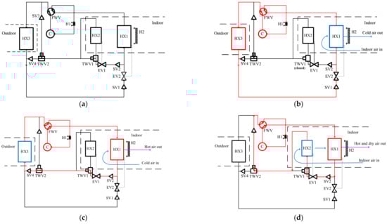
Figure 1.
(a) Schematic diagram of experimental HVAC setup; (b) Refrigerant flow and indoor air flow in A/C mode; (c) Refrigerant flow and indoor air flow in PHP mode; and (d) Refrigerant flow and indoor air flow in proposed DHP mode.
Figure 1b shows the refrigerant flow and indoor air flow of the proposed HVAC system in the A/C operation mode. As shown, the discharged refrigerant from the compressor flows into HX3, which acts as a condenser. After heat rejection in HX3, the condensed liquid refrigerant passes through SV1 and EV2 and enters HX1 (the evaporator). (Note that TWV1 is closed in the A/C mode.) The refrigerant evaporates in HX1, thereby cooling the indoor cabin, and is then flowed back to the compressor.
Figure 1c shows the refrigerant flow and indoor air flow of the proposed HVAC system in the PHP mode. In this mode, FWV is switched such that the refrigerant discharged from the compressor flows into HX1, which then acts as a condenser and heats (but does not humidify) the indoor air. Following heat rejection in HX1, the condensed liquid refrigerant passes through SV2, EV1, TWV1, TWV2 and SV4 and enters HX3 (the evaporator). Finally, the refrigerant evaporates in HX3 and flows back to the compressor.
Figure 1d shows the refrigerant flow and indoor air flow in the proposed DHP mode. FWV is again switched such that the refrigerant discharged from the compressor flows into HX1. Similarly, the condensed liquid refrigerant emerging from the condenser is again passed through SV2, EV1 and TWV1. However, in this case, TWV1 is set such that the refrigerant enters HX2 (the evaporator). The refrigerant evaporates in HX2 and is then flowed back to the compressor through TWV2 and SV3. As the refrigerant evaporates in HX2, it cools and dehumidifies the indoor air, which is passed through HX1 to produce hot and dry air and then directed onto the windshield to provide a defogging function.
In the PHP and DHP modes, heater H1 (installed on the inlet refrigerant side of the compressor) is used to avoid the liquid compression phenomenon at the compressor during operations, while heater H2 installed behind HX1 is used to provide additional heat in extremely cold weather.
The HVAC system shown in Figure 1a–d was arranged within a simulated cabin and the cabin was then placed inside a temperature and humidity test chamber for evaluation purposes. The simulated cabin was construct by six 1 × 1 m2 acrylic plates with thickness of 3 mm and then forming a size of 1 × 1 × 1 m3 (L × W × H). To properly evaluate the performance of the HVAC system, the fluid flow and temperature distribution within the test chamber and simulated cabin must be accurately known. Accordingly, as shown in Figure 2, eleven measuring points were established within the experimental system, including four thermocouples (Nos. 6–1~6–4) placed in the simulated cabin, one thermocouple (No. 1) placed at the return air inlet, another thermocouple (No. 2) placed at the entrance of HX2, and a third thermocouple (No. 3) placed between the exit of HX2 and the entrance of HX1. A fourth thermocouple (No. 4) was additionally placed at the exit of HX1, while a fifth thermocouple (No. 5) was placed at the exit of H2. Finally, two more thermocouples (Nos. 7 and 8) were placed at the entrance and exit of HX3, respectively.
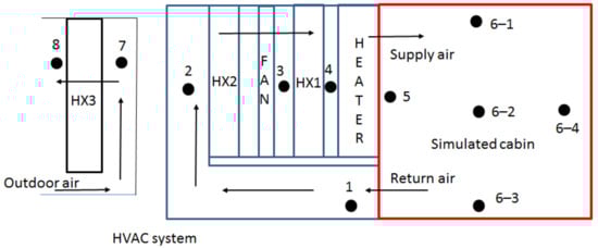
Figure 2.
Locations of measuring points in HVAC system and simulated cabin.
Figure 3 shows HVAC system and the temperature and humidity test chamber. The chamber had interior dimensions of 220 × 180 × 210 cm3 (L × W × H) and enabled the temperature to be controlled over the range of −30~50 °C with an accuracy of ±0.3 °C. In addition, the relative humidity (RH) was controllable over the range of 10~98% RH with an accuracy of ±2.5%.
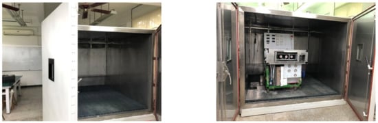
Figure 3.
Photographs of HVAC system and temperature and humidity test chamber.
To reflect the various driving conditions an EV may possibly encounter, the A/C mode of the HVAC system was evaluated for an outdoor air dry bulb temperature of 35 °C and a wet bulb temperature of 24 °C (as specified in the CNS 14464 standard [26]). Similarly, the PHP mode was evaluated for an outdoor air dry bulb temperature of 7 °C and a wet bulb temperature of 6 °C (CNS 14464 [26]). Finally, the DHP mode was evaluated for an outdoor air dry bulb temperature of 27 °C and a wet bulb temperature of 21.2 °C (CNS 12492 [27]). Table 1 summarizes the experimental test conditions.

Table 1.
Test conditions.
When the temperature and humidity in the test chamber reached the state required by the corresponding standard, the compressor of the proposed HVAC system was turned on to start the measurement process. For all of the experiments, the compressor frequency was set as 60.0 Hz and the work done by the compressor was calculated using the measured values of the power input and current obtained using a digital power meter (760401-D, Yokogawa Electric Corporation). For the DHP experiments, the simulated cabin was removed such that the HVAC system functioned directly as a dehumidifier in the temperature and humidity test chamber. Moreover, each test was repeated 3 times.
3. Experimental Data Reduction
3.1. A/C Mode
For the A/C mode, Lee et al. [28] suggested that the air-side heat transfer rate should be set equal to the sum of the air-side sensible and latent heat transfer rates derived from the air temperature change and water vapor mass transfer, respectively. According to Lee et al. [28], the air-side heat transfer rate of HX1, i.e., , was set as
where is the indoor air supply mass flow rate; and h3 and h4 are the enthalpies of measurement points 3 and 4, respectively.
The COP of the proposed HVAC system was then calculated as
where is the power consumption of the compressor.
3.2. PHP Mode
The PHP mode involves only sensible heat exchange. Consequently, the air-side heat transfer rate of HX1 can be derived simply as
where Cp is the specific heat of the air.
The COP of the proposed HVAC system was then calculated as
3.3. DHP Mode
The CNS 12492 standard in Taiwan [27] specifies a daily dehumidification capacity of at least 12 l/day for large dehumidifiers and a corresponding dehumidification performance of more than 1.4 l/kW-h power consumption. Thus, the HVAC requirement in the DHP mode was set as
3.4. Data Acquisition System
The data of interest in the experimental system, namely the mass flow rate, temperature, pressure and air velocity were captured by an MV2000 Data Acquisition Unit (YOKOGAWA, Tokyo, Japan), converted into digital values, displayed in real-time on a monitor. The power consumption of the compressor was measured by a digital power meter (760401-D, YOKOGAWA, Tokyo, Japan). The measured data then interfaced to a notebook, converted into digitized readable values and then saved to disk for further processing.
3.5. Instrumentation Accuracy
To ensure the accuracy of the measurement data, all of the measuring devices were calibrated prior to the main experimental trials. As shown in Table 2, the temperature sensors (T-type) used to measure the refrigerant and air temperatures had an accuracy of ±0.1 °C while the accubalance air capture hood (model: TSI 8380) used to measure the supply air mass flow rate had an accuracy of 3.0%. The digital power meter used to measure the compressor power input had an accuracy of 0.2%. Finally, the anemometer (SwemaAir 40, SWEMA, Farsta, Sweden) used to measure the air speed had an accuracy of ±0.04 m/s for air flow rates in the range of 0.1~1.33 m/s and ±3% for air flow rates in the range of 1.33~30 m/s.
Table 2.
Calibration results.
4. Results and Discussion
Figure 4 shows the temperature distribution within the chamber and HVAC system for the A/C mode, in which the dry bulb and wet bulb temperatures in the chamber were controlled at 35 °C and 24 °C, respectively. From Figure 4, it can be seen that the time constant is approximately 40 min for the system to reach steady-state conditions (as indicated by a variation of less than 0.1 °C/min in the average of cabin temperatures). It can also be seen that all of the measurement points within the simulated cabin (i.e., points 6–1~6–4) reach a temperature of less than 25 °C within five minutes of the system being turned on. Moreover, after ten minutes, the temperatures in the simulated cabin are all less than 20 °C. Under steady-state conditions, the temperatures reduce further to around 15 °C. In other words, the cooling performance of the proposed HVAC system is confirmed.
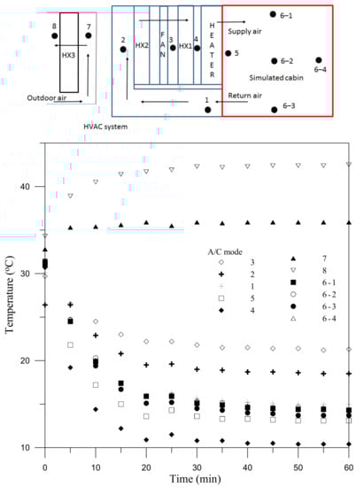
Figure 4.
Temperature distribution in A/C mode.
The average supply air volume flow rate in the A/C mode was found to be 0.1306 m3/s. Moreover, the air density (measured at 27 °C) was 1.18 kg/m3. Consequently, the supply air mass flow rate, , was calculated to be 0.1541 kg/s. At steady state, the inlet temperature and relative humidity of HX1 (T3) were 21.3 °C and 60.0%, respectively. Consequently, the corresponding enthalpy (h3) was obtained as 45.58 kJ/kg. Moreover, the steady-state outlet temperature and relative humidity of HX1 (T4) were measured to be 10.4 °C and 90.0%, respectively. As a result, the corresponding enthalpy (h4) was obtained as 28.29 kJ/kg; giving a difference (h3–h4) of 17.29 kJ/kg between them. In accordance with Equation (1), the air-side heat transfer rate of HX1 () was thus determined to be 2.665 kJ/s. The power consumption of the compressor (Wc) was measured to be 0.837 kW. Thus, in accordance with Equation (2), the COPA/C of the A/C mode was computed as COPA/C = 2.665/0.837 = 3.18.
Figure 5 shows the temperature distribution within the chamber and HVAC system in the PHP mode, for which the dry and wet bulb temperatures in the chamber were set as 7 °C and 6 °C, respectively. After 10 min, the temperatures within the cabin (points 6–1~6–4) all reach 30 °C. Furthermore, under steady-state conditions, all of the temperatures exceed 40 °C. In other words, the ability of the HVAC system to heat the cabin interior under low-temperature conditions is confirmed.
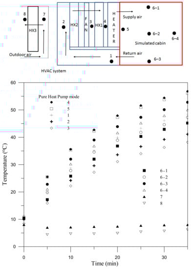
Figure 5.
Temperature distribution in PHP mode.
In the PHP mode, the average supply air mass flow rate of the system was again equal to 0.1306 m3/s. Given the same air density (i.e., 1.18 kg/m3) the supply air mass flow rate, , was thus found to be 0.1541 kg/s once again. Under steady-state conditions, the inlet and outlet temperatures of HX1 (T3 and T4) were 38.2 °C and 56.8 °C, respectively. Thus, taking a value of Cp = 1.005 J/(kg K) in Equation (3), the air-side heat transfer rate of HX1 () was calculated to be 2.881 kW. The power consumption of the compressor (Wc) was measured to be 0.872 kW. Consequently, from Equation (4), the COPPHP of the PHP mode was calculated to be COPPHP = 2.881/0.872 = 3.3.
In evaluating the performance of the DHP mode, the dry bulb and wet bulb temperatures in the chamber were set as 27 °C and 21.2 °C, respectively, and the HVAC system (without the simulated cabin) was run continuously for 24 h. The dehumidification capacity of the system (i.e., the average water removal per hour) was found to be 1.274 L/h. Meanwhile, the hourly power consumption of the system was calculated to be 0.867 kW. Consequently, the dehumidification performance of the DHP mode was determined to be 1.274 (L/h)/0.867 kW = 1.47 L/(kW-h) ≧ 1.4 L/(kW-h). In other words, the DHP mode satisfies the dehumidification requirement specified in the CNS 12492 standard.
Figure 6 shows the temperature distribution within the test chamber given the use of the DHP mode. The results indicate that the return air cooled and dehumidified by HX2 has a temperature of around 17 °C. However, after passing through HX1, the air temperature increases to approximately 40 °C. In other words, in addition to the dehumidification effect described above, the DHP mode also raises the air temperature within the HVAC system by around 13 °C (40 °C–27 °C).
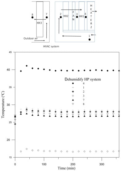
Figure 6.
Temperature distribution in DHP mode.
Table 3 shows a comprehensive comparison between the present study and the other HVAC system for EVs. It can be seen that the COP of the pure heat pump for the present study is slightly larger than that of the other studies. Moreover, Telsa’s official website [29] shows that Telsa replace the heater matrix, which would have had engine coolant running through it, with an electric heater that has 400 volts running through it. Because the COP of electric heater is less than 1. In other words, it means the COP of the heating system of Telsa is much less than using a pure heat pump. Moreover, the present study is the only HVAC system with Defog Heat Pump (simultaneously heating/dehumidifying) functions.
Table 3.
Comparison of HVAC systems with the other studies.
Compare the temperature distribution in Figure 4, Figure 5 and Figure 6. The lowest temperature in Figure 4 is point 4, which is the outlet of HX1 (i.e., evaporator of A/C mode). Meanwhile, the highest temperature is point 8, which is the outlet of HX3 (i.e., condenser of A/C mode). Moreover, the lowest temperature in Figure 5 is point 8, which is the exit of HX 3 (i.e., evaporator of PHP mode). The highest temperature is point 4, which is the outlet of HX1 (i.e., condenser of PHP mode). Figure 4 and Figure 5 show the switch between simple air-conditioning and heating (i.e., evaporator and condenser are interchanged), so the highest temperature and lowest temperature positions are just interchanged. In addition, the lowest temperature in Figure 6 is point 3, which is the outlet of HX2 (i.e., evaporator of DHP mode). The highest temperature is point 4, which is the outlet of HX1 (i.e., condenser of DHP mode). From above discussion, it can be seen that the highest temperature of different modes all appear at the outlet of the condenser, and the lowest temperature all appear at the outlet of the evaporator.
5. Conclusions
The pure heat pump systems used in EVs provide an efficient means of heating the vehicle interior without significantly reducing the mileage. However, they do not provide a dehumidification function while heating. Consequently, in cold weather, the interior surface of the windshield tends to fog; posing serious road safety concerns. Therefore, EVs use A/C system to cool the cabin air then achieving the dehumidification purpose and use PTC electric heaters to reheat the cooled cabin air [30,31]. However, the COP of the PTC heating system is low (i.e., ≤1). Accordingly, this study has proposed a novel high-efficiency HVAC system which not only provides the conventional A/C and Pure Heat Pump (PHP) modes of a traditional EV HVAC system, but also provides an additional Defog Heat Pump (DHP) mode through the combined use of two heat exchangers (one evaporator and one condenser) and a heater. The performance of the A/C, PHP and DHP modes has been evaluated experimentally in a temperature and humidity control chamber using the dry and wet bulb temperatures specified in the corresponding CNS standards (namely CNS 14464 and CNS 12492). The main findings of this study can be summarized as follows:
- In the A/C mode, the temperature within the simulated cabin reduces to less than 25 °C in five minutes and falls to around 15 °C under steady state conditions. The corresponding COPA/C is 3.18.
- In the PHP mode, the cabin temperature rises to 30 °C within 10 min and increases to approximately 40 °C at steady state. The corresponding COPPHP is 3.3.
- In the DHP mode, the air sucked from the temperature and humidity test chamber at 27 °C is dehumidified and reduced to a temperature of around 17 °C by an evaporator and is then passed through a condenser, where it is heated to a temperature of around 40 °C. The dehumidification performance of the DHP mode is equal to 1.47 L/kW-h, and hence exceeds the minimum requirement of 1.4 L/kW-h laid down in the corresponding standard (CNS 12492).
- When the outdoor temperature is too low and using PHP mode, the freezing phenomena will occur on the outdoor HX3, than will affect the performance of PHP. Moreover, It is currently a laboratory test and will be installed in the car for on-road test in the future.
Author Contributions
T.-B.C. contributed to conceive and design the experiments, analyze the data, and write the paper; J.-J.S. contributed to perform the experiments; J.-W.H. contributed to perform the experiments. All authors have read and agreed to the published version of the manuscript.
Funding
This research was funded by the Ministry of Science and Technology (MOST) of Taiwan, grant numbers MOST 107-2221-E-415-017 and MOST 108-2221-E-415-012.
Conflicts of Interest
The authors declare no conflict of interest.
References
- Núñez-Cacho, P.; Górecki, J.; Molina-Moreno, V.; Corpas-Iglesias, F.A. What gets measured, gets done: Development of a circular economy measurement scale for building industry. Sustainability 2018, 10, 2340. [Google Scholar] [CrossRef]
- Jin, H.; Teng, Y.; Zhang, T.; Wang, Z.; Chen, Z. A deep neural network coordination model for electric heating and cooling loads based on IoT data. CSEE J. Power Energy Syst. 2020, 6, 22–30. [Google Scholar] [CrossRef]
- Kristoffersen, T.K.; Capion, K.; Meibom, P. Optimal charging of electric drive vehicles in a market environment. Appl. Energy 2011, 88, 1940–1948. [Google Scholar] [CrossRef]
- Farrington, R.; Rugh, J. Impact of Vehicle Air-Conditioning on Fuel Economy, Tailpipe Emissions, and Electric Vehicle Range; NREL/CP-540-28960; National Renewable Energy Laboratory: Golden, CO, USA, 2000. [Google Scholar]
- Zhang, J.Z. Structural features of fully electric air conditioning system. Automob. Maint. 2006, 12, 4–5. [Google Scholar]
- Guyonvarch, G.; Aloup, C.; Petitjean, C.; Savasse, A.D.M.D. 42V Electric Air Conditioning Systems (E-A/CS) for Low Emissions, Architecture, Comfort and Safety of Next Generation Vehicles; SAE Technical Paper No. 2001-01-2500; SAE International: Warrendale, PA, USA, 2001. [Google Scholar]
- Martín, J.M.M.; Martínez, J.M.G.; Moreno, V.M.; Rodríguez, A.S. An analysis of the tourist mobility in the island of Lanzarote: Car rental versus more sustainable transportation alternatives. Sustainability 2019, 11, 739. [Google Scholar] [CrossRef]
- Weckerle, C.; Nasir, M.; Hegner, R.; Bürger, I.; Linder, M. A metal hydride air-conditioning system for fuel cell vehicles –Performance investigations. Appl. Energy 2019, 256, 113957. [Google Scholar] [CrossRef]
- Weckerle, C.; Nasir, M.; Hegner, R.; Bürger, I.; Linder, M. A metal hydride air-conditioning system for fuel cell vehicles—Functional demonstration. Appl. Energy 2020, 259, 114187. [Google Scholar] [CrossRef]
- Cheng, Y.T.; Huang, S.J. Research on Intelligent Constant Temperature Air Conditioning Heat Pump System for Electric Vehicles. In The 18th National Conference on Vehicle Engineering; NPUST: Pingtung, Taiwan, 2013. [Google Scholar]
- Cho, C.W.; Lee, H.S.; Won, J.P.; Lee, M.Y. Measurement and evaluation of heating performance of heat pump system using wasted heat of electric devices for an electric bus. Energies 2012, 5, 658–669. [Google Scholar] [CrossRef]
- Lee, H.S.; Won, J.P.; Cho, C.W.; Kim, Y.C.; Lee, M.Y. Heating performance characteristics of stack coolant source heat pump using R744 for fuel cell electric vehicles. J. Mech. Sci. Technol. 2012, 26, 2065–2071. [Google Scholar] [CrossRef]
- Lee, D.Y.; Cho, C.W.; Won, J.P.; Park, Y.C.; Lee, M.Y. Performance characteristics of mobile heat pump for a large passenger electric vehicle. Appl. Therm. Eng. 2013, 50, 660–669. [Google Scholar] [CrossRef]
- Ahn, J.H.; Kang, H.; Lee, H.S.; Jung, H.W.; Baek, C.; Kim, Y. Heating performance characteristics of a dual source heat pump using air and waste heat in electric vehicles. Appl. Energy 2014, 119, 1–9. [Google Scholar] [CrossRef]
- Lee, D. Experimental study on the heat pump system using R134a refrigerant for zero-emission vehicles. Int. J. Automot. Technol. 2015, 16, 923–928. [Google Scholar] [CrossRef]
- Han, X.; Zou, H.; Wu, J.; Tian, C.; Tang, M.; Huang, G. Investigation on the heating performance of the heat pump with waste heat recovery for the electric bus. Renew. Energy 2020, 152, 835–848, in press. [Google Scholar] [CrossRef]
- Choi, D.; An, Y.; Lee, N.; Park, J.; Lee, J. Comparative Study of Physics-Based Modeling and Neural Network Approach to Predict Cooling in Vehicle Integrated Thermal Management System. Energies 2020, 13, 5301. [Google Scholar] [CrossRef]
- Yue, C.; Tong, L.; Zhang, S. Thermal and economic analysis on vehicle energy supplying system based on waste heat recovery organic Rankine cycle. Appl. Energy 2019, 248, 241–255. [Google Scholar] [CrossRef]
- Ding, P.; Wang, Z.; Wang, Y.; Li, K. A distributed multiple-heat source staged heating method in an electric vehicle. Renew. Energy 2020, 150, 1010–1018, in press. [Google Scholar] [CrossRef]
- Ramli, W.R.B.W.; Pesyridis, A.; Gohil, D.; Alshammari, F. Organic Rankine CycleWaste Heat Recovery for Passenger Hybrid Electric Vehicles. Energies 2020, 13, 4532. [Google Scholar] [CrossRef]
- Qi, Z.G. Advances on air conditioning and heat pump system in electric vehicles—A review. Renew. Sustain. Energy Rev. 2014, 38, 754–764. [Google Scholar] [CrossRef]
- Peng, Q.; Du, Q. Progress in Heat Pump Air Conditioning Systems for Electric Vehicles—A Review. Energies 2016, 9, 240. [Google Scholar] [CrossRef]
- Yang, Y.; Huang, Y.; Zhao, J. Optimization of the automotive air conditioning strategy based on the study of dewing phenomenon and defogging progress. Appl. Therm. Eng. 2020, 169, 114932. [Google Scholar] [CrossRef]
- Wang, M.; Urbank, T.M.; Sangwan, K.V. “Clear Vision” automatic windshield defogging system. SAE Tech. Pap. 2004, 113, 939–947. [Google Scholar]
- Seo, J.H.; Kim, H.J.; Jung, K.J.; Kim, D.W.; Yeom, J.K.; Lee, M.Y. Review of conventional air conditioning system for internal combustion engines. Int. J. Air-Cond. Refrig. 2013, 21, 1330001. [Google Scholar] [CrossRef]
- CNS 14464 standard, Non-Ducted air Conditioners and Heat Pumps—Testing and Rating for Performance. Available online: https://www.cnsonline.com.tw/ (accessed on 22 November 2020).
- CNS 12492 Standard, Dehumidifiers. Available online: https://www.cnsonline.com.tw/ (accessed on 22 November 2020).
- Lee, M.Y.; Kim, Y.H.; Lee, H.S.; Kim, Y.C. Air-side heat transfer characteristics of flat plate finned-tube heat exchangers with large fin pitches under frosting conditions. Int. J. Heat Mass Transf. 2010, 53, 2655–2661. [Google Scholar] [CrossRef]
- Telsa Official Website. Available online: https://www.tesla.com/zh_TW/blog/blowing-hot-and-cold?redirect=no (accessed on 22 November 2020).
- Tang, X.; Guo, Q.; Li, M.; Jiang, M. Heating Performance Characteristics of an Electric Vehicle Heat Pump Air Conditioning System Based on Exergy Analysis. Energies 2020, 13, 2868. [Google Scholar] [CrossRef]
- Park, M.; Kim, S.C. Heating Performance Enhancement of High Capacity PTC Heater with Modified Louver Fin for Electric Vehicles. Energies 2019, 12, 2900. [Google Scholar] [CrossRef]
Publisher’s Note: MDPI stays neutral with regard to jurisdictional claims in published maps and institutional affiliations. |
© 2020 by the authors. Licensee MDPI, Basel, Switzerland. This article is an open access article distributed under the terms and conditions of the Creative Commons Attribution (CC BY) license (http://creativecommons.org/licenses/by/4.0/).