Article

Flare Gas Waste Heat Recovery: Assessment of Organic Rankine Cycle for Electricity Production and Possible Coupling with Absorption Chiller

1
Mechanical Engineering Department, National Polytechnic School of Constantine, BP75, A, Nouvelle Ville Ali Mendjli, Constantine 25000, Algeria
2
Mechanical Engineering Department, Faculty of Applied Sciences and Engineering, Universiy Akli Mohand Oulhadj—Bouira, Rue Drissi Yahia, Bouira 10000, Algeria
3
Laboratoire Energétique, Mécanique et Ingénieries (LEMI), Energy Department, Faculty of Engineering des Sciences, Université M’hamed Bougara, Avenue de l’Indépendance, Boumerdès 35000, Algeria
4
INVIVO Expertises, 13 rue de Clermont, 44000 Nantes, France
5
Laboratory of Energetics and Theoretical and Applied Mechanics, University of Lorraine, 2 av. de la Forêt de Haye, 54504 Vandoeuvre CEDEX, France
*
Author to whom correspondence should be addressed.
Energies 2020, 13(9), 2265; https://doi.org/10.3390/en13092265
Submission received: 31 March 2020 / Revised: 20 April 2020 / Accepted: 22 April 2020 / Published: 4 May 2020

Abstract

:
Every year, flare gas is responsible for more than 350 million tons of CO2 emissions. Aside from thermal and environmental pollution impacts, flare gas contributes to global warming and enormous economic losses. Thus, waste heat recovery due to flaring gas can be explored through Organic Rankine Cycle ORC systems for electricity production. In this context, the assessment of a toluene ORC system is proposed for a potential application in an Algerian petrochemical unit. The study focuses mainly on highlighting the potential and thermodynamic performances of the ORC application to produce electricity and potential cooling thanks to coupling an absorption chiller by recovering heat due to flaring gas. Such a solution can easily be implemented as an energy efficiency key solution. The ORC electrical production can meet the increasing demand of natural gas initially intended to be provided to a gas power plant and assures the major part of the Algerian electrical production.

Graphical Abstract

1. Introduction

One of the major environmental problems related to the gas and oil industry is the unwanted natural gas released to the atmosphere by flaring [1]. The increased flaring gas process is caused by the increased demand of oil and gas production in addition to the pressure relief requirement in abnormal conditions [2] for safety purposes at refinery facilities. It should be considered that flaring enormous quantities of natural gas is an economic capital waste and is a major source of the reported important quantities of emitted gas components, such as carbon dioxide, methane, sulfur, NOx, volatile organic compounds (VOCs), and black carbon [3]. Statistical reports provided an amount of 400 million tons of CO2 emitted from about 150 billion cubic meters per year flared gas all around the world [4,5]. These emissions are dominated by the upstream petroleum sector [6]. Therefore, it is highly required to reduce the flared gas by improving the actual flaring gas techniques and to look for new recovery technologies that can be used for electricity production or alternative efficient applications. For the oil and gas industry, natural gas that would otherwise be flared can instead be used to produce heat power that is able to be recovered for electricity generation, thus significantly reducing emissions.
Flaring gas can be reduced and/or recovered by means of different techniques, including, i.e., redistribution in the natural gas distribution networks, transported via pipeline (Piped Natural Gas -PNG), re-injected for enhanced oil recovery, used as feedstock for the petrochemical manufacturing, and used for electricity generation [7]. The latter technique was the focus of some recent studies and is the subject of the present investigation. For example, Heidari et al. [8] compared two novel methods for generating electrical power using the flare gas with a flow rate from 0 to 2.14 kg/s. The first method is burning the mixture of the flare gas and a conventional fuel, while the second method is based on sending the flare gas to an intermediate stage of a gas turbine after burning it in a combustor. Results show that the first scenario is preferable from technical and economic aspects for all of the flare and natural gas flow rates except when the amount of the flare flow rate in the plant is lower than 0.8 kg/s. The same authors [9] also compared two scenarios of electrical power generation-based flared gas. The first scenario assumed a gas turbine working in a simple Brayton cycle while the second scenario considered a simple cycle of the gas turbine-based Fog method. The comparison-based technical and economic aspects showed that the second scenario generates higher power with a difference of about 1.75 MW while the first scenario is more economically acceptable. Ojijiagwo et al. [10] and Ojijiagwo et al. [11] studied the technological and economic implications of the use of gas to wire (GTW) technology to manage gas flare for electricity generation, particularly in Nigeria. The economic analyses point out a potential net profit of £2.68 billion from flare gas prevention. The prevented flare gas can substitute the initially daily feed gas of 46.5 MCM required for gas turbines to generate around 7500 MW of electricity. Anosike [12] simulated and compared different gas turbines used for converting waste from flared gas and from pure natural gas in Nigeria. The comparison showed that both fuels have a similar performance and the recovered flared gas can be used efficiently in electricity generation using conventional gas turbines. Rahimpour et al. [2] investigated three methods: Gas-to-liquid (GTL) production, electricity generation with a gas turbine, and compression and injection into the refinery pipelines, via simulation and economic evaluation for Asalooye gas refinery to recover and reuse flare gases. Results showed that 48,056 barrels per day of valuable GTL products are produced by the GTL method. The electricity generation method provides 2130 MW electricity and the gas compression method provides a compressed natural gas with 129 bar of pressure for injection to the refinery pipelines. In addition, the economics evaluation results show that the gas compression technique is the most economical approach in Asalooye gas refinery with a medium capital investment owing to lower capital investment costs and higher return investment rate. Rahimpour et al. [13] did the same work for Farash band gas refinery. Results showed that electricity generation is the most appropriate solution economically. Hajizadeh et al. [14] evaluated and simulated the feasibility of three methods for flare gas recovery (FGR) using Aspen HYSYS and Aspen EDR simulation software in a giant gas refinery in Iran. These methods include liquefaction, LPG (liquefied petroleum gas) production, and a gas compression unit. The liquefaction and LPG production units existed in the plant and can be used for FGR. Results indicate that operating a flash drum at 1 barg of pressure leads to maximum liquid extraction from flare gas, while operation at 0.75 barg gives maximum LPG production. Using the FGR methods, more than 80% of flare gases can be recovered, which stops about 205 ton/day CO2 equivalent emission. The economic analysis showed that the rate of return (ROR) for liquefaction and LPG methods is above 200%. Al-Fehdly et al. [15] proposed an alternative energy utilization solution that can reduce the energy waste as well as the carbon footprint of crude oil production estimated in Iraq. This solution is to use the flared gas in generating electricity instead of the adopted method of using fossil fuel, which potentially saves about 50 million tons of carbon dioxide annually as per today’s production rates. Adekomaya et al. [16] made the Nigerian government aware of the enormous gap in the power supply and demand in order to control the generation of electricity. They highlighted the linkages between gas flaring and its impact on energy growth and sustainability. Iora et al. [17] focused on the on-site electricity generation from an annual average yield of 1150 Nm3/h of associated gas. The analysis was carried out by comparing, both from the economic and environmental points of view, various power plant technologies for the generation of electric power in the proximity of the oil field. It turned out that adopting a scheme with non-derated internal-combustion engines (ICEs) fed by treated gas, and partial gas flaring, the most cost-effective result was obtained, showing an important payback time of about 5 years and an internal rate of return (IRR) of 42.2%. Tahouni et al. [18] presented a novel methodology of a fuel gas network (FGN) based on the model of Hasan el al. [19]. They developed new constraints for flaring emissions mostly for CO2 emissions. Additionally, they proposed a profit-based retrofit model for the integration of flare gas streams in FGNs. The refinery case study proved that the use of a flared gas stream to the network, the novel model of FGN, can reduce energy costs and flaring emissions. Comodi et al. [20] investigated the deployment of a liquid ring compressor to treat flare gas and reuse it. The flare gas recovering flow rate of 400 kg/h was performed. Such a solution was economically profitable with an interesting payback time estimated at less than 3 years.
The generation of electrical power can be achieved by means of different alternative and well-developed techniques, such as the steam Rankine cycle (SRC), which uses the dissipated heat from the waste heat boiler to generate steam that drives a turbine [21]. The organic Rankine cycle (ORC) is also a recently developed technique, which uses organic working fluids instead of water. These fluids are generally selected based on the investigated application, temperature levels, and the environmental impact in terms of the ozone depletion potential (ODP) and global warming potential (GWP) [22].
As a negative consequence of the natural gas flaring and the new initiatives endorsed by the World Bank to some concerned countries and oil and gas companies to end routine gas flaring by 2030 [23], the objective of this study was to propose a thermodynamic analysis-based ORC system for waste heat recovery from gas flaring in Algeria. Contrarily to pollutant information emissions from gas flaring activities that can be provided by a satellite [24], in situ potential estimation of the flare gas heat source is very difficult because of challenging measurement due to the noticeable changing of gas composition at high flow velocities as reported by Emam [25]. Therefore, Ziyarati et al. [26] implemented one model, allowing a good estimation of both the flow rate and gas composition of gas feeding the flare system.
The present work focused on the assessment of a toluene ORC system for power generation from an annual average yield ranging from 100 to around 1000 Nm3/h of associated flaring gas [17]. Because of the high velocities and flow rate variation of flare gas, the ORC system risks off-design operating conditions. This is the main reason for which toluene was selected as the working fluid for this application since toluene figured among the fluids with the highest net power outputs at low loads [27] and supports high temperature ranges over 300 °C [28]. An integration of an absorption chiller activated by the condenser rejected heat was rapidly investigated with important cooling capacities.
In addition, and to the best of our knowledge, there is a lack of research studies on natural gas flaring and more particularly in Algeria. Therefore, this study takes up this challenge by considering and applying the present proposed ORC system to a potential application for waste heat recovery in an Algerian petrochemical unit. Publications dealing with ORC application for flare gas waste heat recovery are very limited and no detailed thermodynamic analysis-based ORC system for the waste heat recovery from gas flaring applications is available. Thus, the focus of the present paper was to contribute to the enhancement of knowledge about the feasibility and the application of this technique for waste heat recovery from a flaring gas source in a well-known oil- and gas-producing country, such as Algeria.
Reducing the flare is identified as a key action for the implementation of the sustainable development goals [29] and to comply with the endorsed zero routine initiative and the Paris agreement, declining as Nationally Determined Contribution (NDC) in Algeria [30].
Therefore, the rest of the paper is devoted to presenting the thermodynamic model in terms of energy and exergy analysis for both flare gas and ORC systems. Thereafter, the simulation results are presented and discussed. The conclusions are noted at the end of the paper, pointing out an important potential for ORC applications even for electricity production and cooling owing to a possible coupling with an absorption chiller.

2. Thermodynamic Model

Thermodynamic analysis concerns a flare gas waste heat recovery system using a toluene ORC cycle as depicted by Figure 1. The thermodynamic study was performed based on a couple of assumptions summarized as follows:
  • Steady state operating mode of the ORC cycle [31,32]
  • Neglecting pressure drops at each side of the heat exchangers [31,32]
  • Neglecting both variation of both kinetic and potential energies [31,32]
  • Turbine and feeding pump isentropic efficiencies fixed at 0.8 [28]
  • Tev = 300 °C, considered as the highest temperature for the high-temperature working fluid [28]
  • Tc = 120 °C; fixed based on the corresponding saturation pressure, Psat = 1.31 bar > Patm
  • Ideal conversion from mechanical to electrical power
  • Sub cooling and super heating respectively fixed at ΔTsub = 5 °C [33] and ΔTsup = 0 °C [32] for the basic configuration
  • Flare gas considered as semi perfect, meaning that the thermophysical properties depend only on the temperature contrarily to the ideal gas with constant thermophysical properties.
Then, both the specific enthalpy and entropy are defined respectively as:
d H = m ˙ f g . d h d h = C p f g ( T ) . d T ,
d S = m ˙ f g d s d s = C p f g ( T ) d T T R d P P d s = C p f g ( T ) d T T w i t h d P P = 0 .
The expression of specific entropy is obtained when neglecting the pressure drops.

2.1. Specific Heat Capacity Model of the Flare Gas

The specific heat capacity of combustion products, flare gas, depends on the temperature variation [34]; this is why the gas is qualified as semi-perfect, and considering it as constant may disturb a good quantification of the available heat of the source. These risks also have a direct impact on the enthalpy and entropy calculations since both terms are defined based on the specific heat capacity.
The thermodynamic database used to perform the required calculation of the ORC, Cool Prop, is not able to be used directly to prevent accurate enthalpy and entropy calculation for the present flare gas composition since such a specific mixture is not available within the mentioned data base. Thus, the calculation is made possible through two mains steps: Defining the typical flaring gas composition within the Cool Prop tool, and then deducing its specific heat. After this, a sensitive analysis on the computed specific heat is performed and a fitting curve for the variation of the specific heat versus temperature is obtained. It should be noted that the elementary chemical compounds of the typical flare gas composition are all available within the Cool Prop database.
A typical flare gas composition was considered for the present work as reported previously by Emam [25]. Such composition was assumed for the present preliminary study. However, experimental measurements are highly recommended when a physical ORC deployment is expected in order to assure an accurate-sizing step of the whole ORC solution during the tendency modeling step.
As mentioned previously, the composition of the flare gas was introduced within CoolProp [35] for the calculation of specific heat capacity for a range of temperature sources. The interpolation of the different points of Cp allowed implementation of the next fitting curve expression for which all coefficients are defined in Table 1:
C p f g ( T ) = A T 6 + B T 5 + C T 4 + D T 3 + E T 2 + F T + G .
Therefore, the integration of this last expression will allow accurate calculation of the enthalpy and entropy (inlet/outlet). Their respective expressions are given then:
h = T h s i T h s o 2 C p f g ( T ) d T = A T 7 7 + B T 6 6 + C T 5 5 + D T 4 4 + E T 3 3 + F T 2 2 + G T T h s i T h s o 2 ,
s = T h s i T h s o 2 C p f g ( T ) d T T = A T 6 6 + B T 5 5 + C T 4 4 + D T 3 3 + E T 2 2 + F T + G ln ( T ) T h s i T h s o 2 .

2.2. ORC Cycle Thermodynamic Model

The thermodynamic model of the ORC cycle deals with energy and exergy analysis by considering all abovementioned assumptions.

2.2.1. Energy Analysis

The thermodynamic model was carried out based on the previous work of Le et al. [31].
As shown in Figure 2, the subcooled organic working fluid is firstly pressurized to the high pressure of the steam generator. This thermodynamic transformation required mechanical power, such as:
W ˙ p = m ˙ w f ( h c h b ) .
The working fluid is preheated and then evaporated into saturated steam. This transformation is made possible by recovering the heat available in the flare gas. Consequently, a waste heat is recovered to feed freely the ORC system. Thereby, the temperature of flue gas is drastically reduced, leading to an important reduction of the thermal pollution. The overall thermal power absorbed at high pressure by the preheater and the evaporator is calculated as:
Q ˙ h p = Q ˙ p r e + Q ˙ e v = m ˙ w f ( h d h c ) + ( h e h d ) = m ˙ w f ( h e h c ) ,
where Q ˙ e v and Q ˙ p r e represent respectively the heat power absorbed by the evaporator and preheater.
The selected working fluid, Toluene, presents a negative slope in the T–s diagram, Figure 2; i.e., dry fluid. Therefore, superheating is no longer required for this basic configuration. Thus, the turbine expansion power can be formulated as:
W ˙ T = m ˙ w f ( h e h f ) .
The expanded steam leaving the turbine is then introduced within the condenser to be respectively cooled, condensed, and then subcooled to protect the feed pump. The rejection power at low pressure occurring during these steps is calculated:
η t h = W ˙ T W ˙ p Q ˙ h p .
Consequently, the thermal performance of the ORC system activated by the recovered heat of the flare gas initially discharged to the atmosphere is defined as follow:
η t h = W ˙ T W ˙ p Q ˙ h p .

2.2.2. Exergy Analysis

The quality of energy analysis is improved through the exergy study. The exergy study focuses on both consumed and destroyed exergy within each element of the ORC cycle. The standard conditions are considered for the dead state.
Therefore, the supplied exergy during the heating step is provided by the heat source. It is expressed as:
E ˙ x h = m ˙ h ( h h i s h h s o ) T 0 ( s h s i s h s o ) .
Then, the working fluid absorbs only one part of the available exergy. Consequently, the absorbed exergy by the high-pressure exchanger, composed of both the preheater and evaporator, can be calculated as:
E ˙ x h p , w f = m ˙ w f ( h e h c ) T 0 ( s e s c ) .
While, the destruction of exergy is quantified by:
I ˙ h p , w f = T 0 m ˙ w f ( s e s c ) + m ˙ h ( s h s o s h s i ) .
The generated steam leaving the evaporator is directed towards the expansion device. This means that available exergy supplied for the expansion process becomes:
E ˙ x T = m ˙ w f ( h e h f ) T 0 ( s e s f ) .
This last expression of the available exergy can be decomposed respectively in two terms: The useful exergy that represents the effective output performed by the turbine (Equation (15)) and the exergy destruction occurring within the turbine (Equation (16)):
W ˙ T = m ˙ w f ( h e h f ) ,
I ˙ T = T 0 m ˙ w f ( s e s f ) .
After the expansion process, the working fluid undergoes transformations leading to the supply of exergy to the cooling medium; this exergy is defined as:
E ˙ x c = m ˙ w f ( h f h b ) T 0 ( s f s b ) .
On the other hand, the cooling medium receives only part of the exergy formulated as:
E ˙ x c m = m ˙ c m ( h c s o h c s i ) T 0 ( s c s o s c s i ) .
The destruction of exergy during the heat rejection in the condenser can be expressed by:
I ˙ c = T 0 m ˙ w f ( s o u t s i n ) + m ˙ c m ( s c s o s c s i ) .
The subcooled fluid leaving the condenser is pressurized to the high pressure of the evaporator. This requires an exergy supply defined as:
W ˙ p = m ˙ w f ( h c h b ) .
Therefore, the working fluid receives the following useful exergy
E ˙ x p = m ˙ w f ( h c h b ) T 0 ( s c s b ) .
The pumping processes generate exergy destruction estimated by the following relation:
I ˙ p = T 0 m ˙ w p ( s c s b ) .
Finally, the overall exergy destruction occurring throughout the ORC cycle is expressed as:
I ˙ t o t = I ˙ p + I ˙ h p , w f + I ˙ T + I ˙ c .
Then, the whole system exergy efficiencies defined by:
η e x = W ˙ T W ˙ p E ˙ x h .
We also define the pressure ratio as follows:
P r a t = P e v P c .
Another ratio, the evaporator heat ratio, is defined for the specific need of the present study:
Q r a t = Q e v Q p r e = ( h e h d ) ( h d h c ) .

3. Results

The obtained results are presented in four separate subsections. The three first subsections focus on the sensitivity analysis of three parameters, including respectively the evaporation temperature, heat source inlet temperature, and super heating temperature. The final subsection is allocated to the integration of the absorption chiller and its impact on the overall performance of the proposed system.

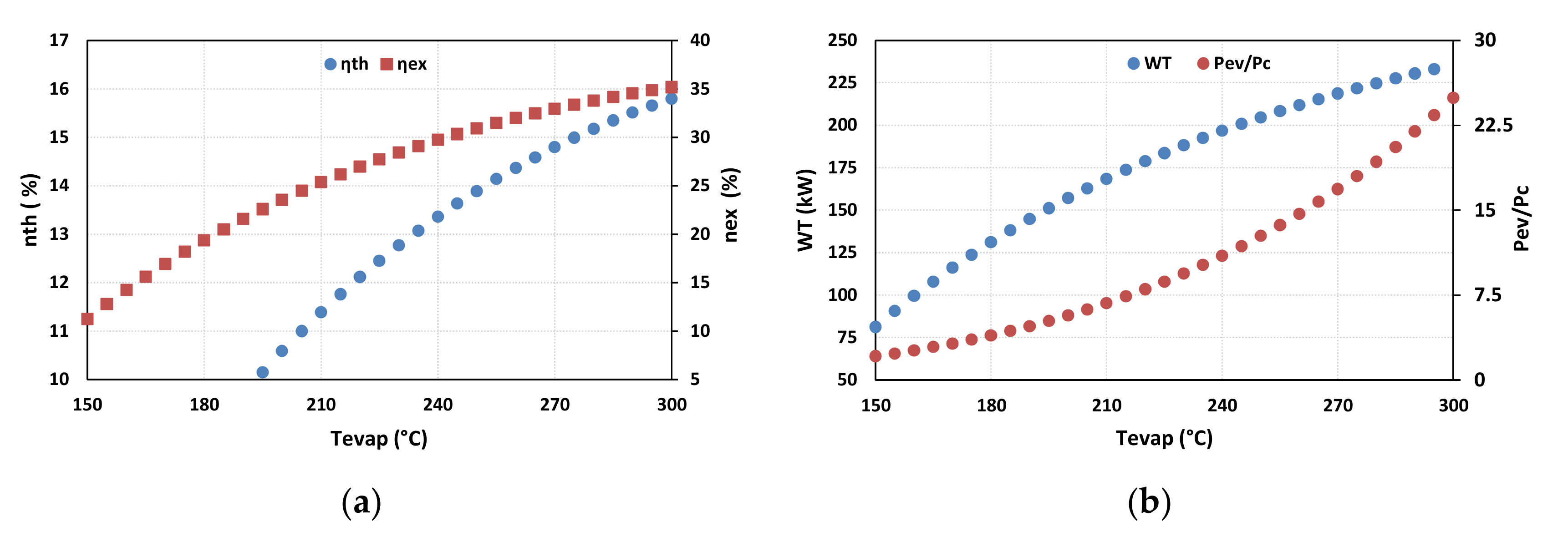
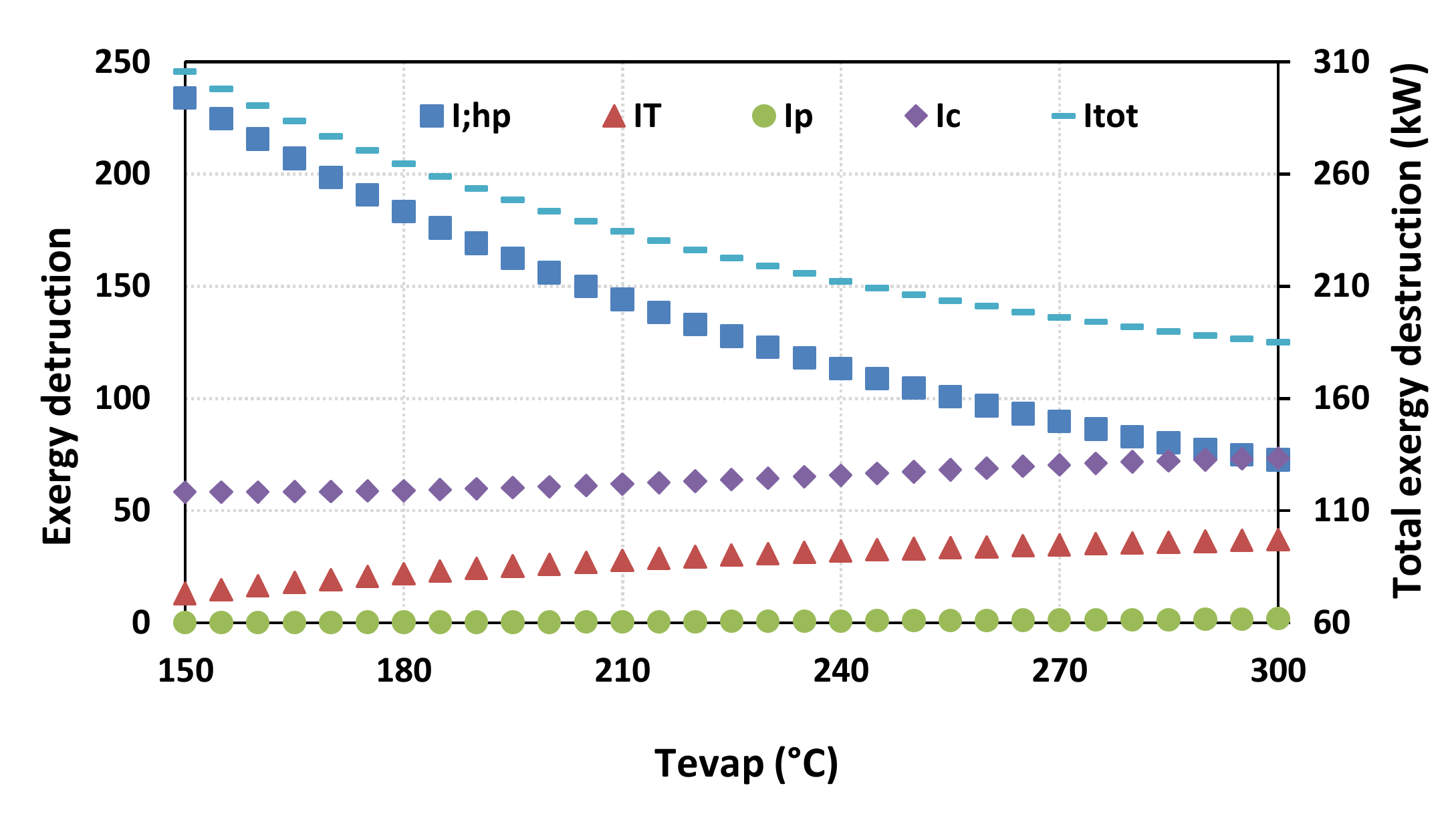
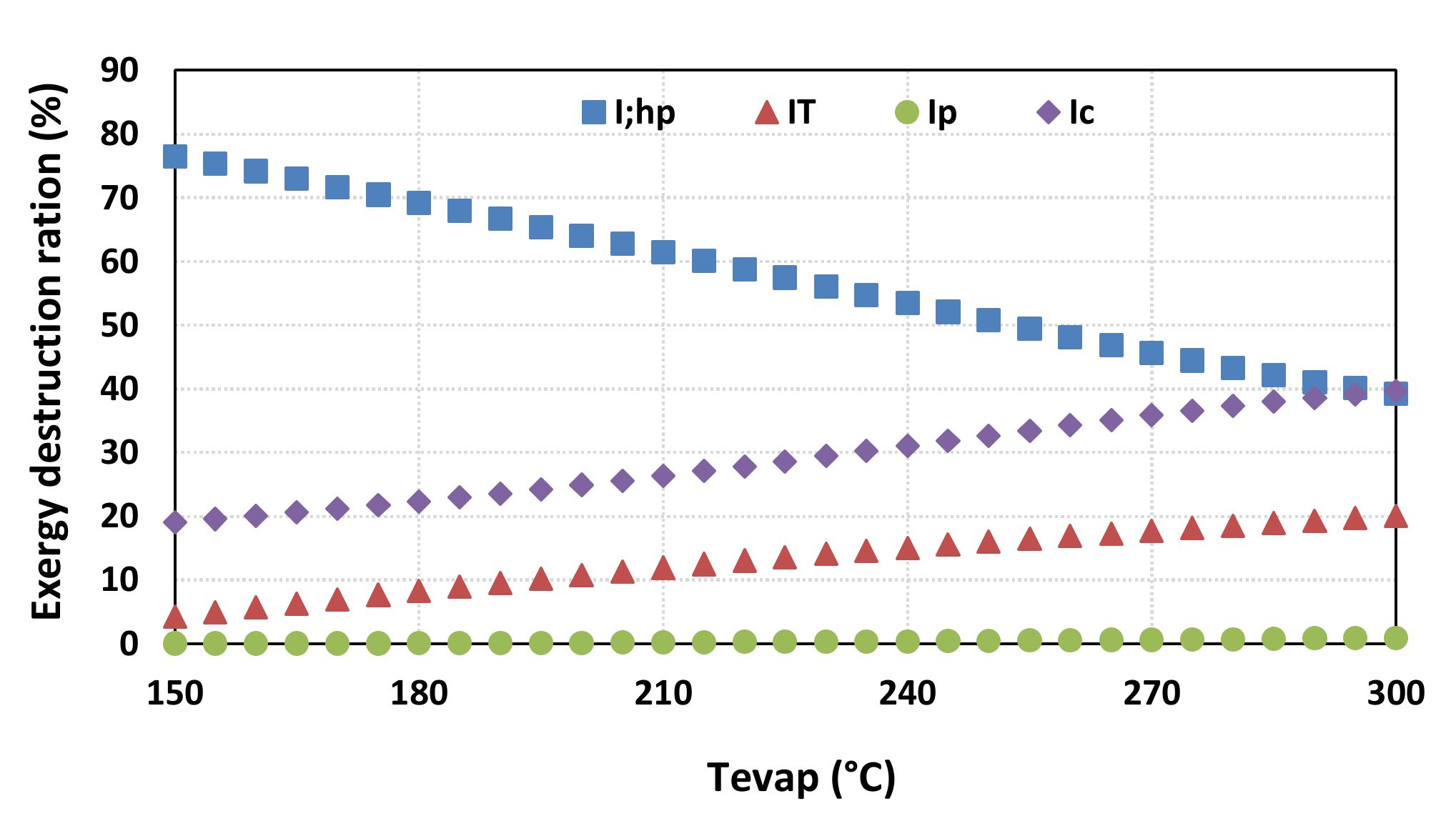
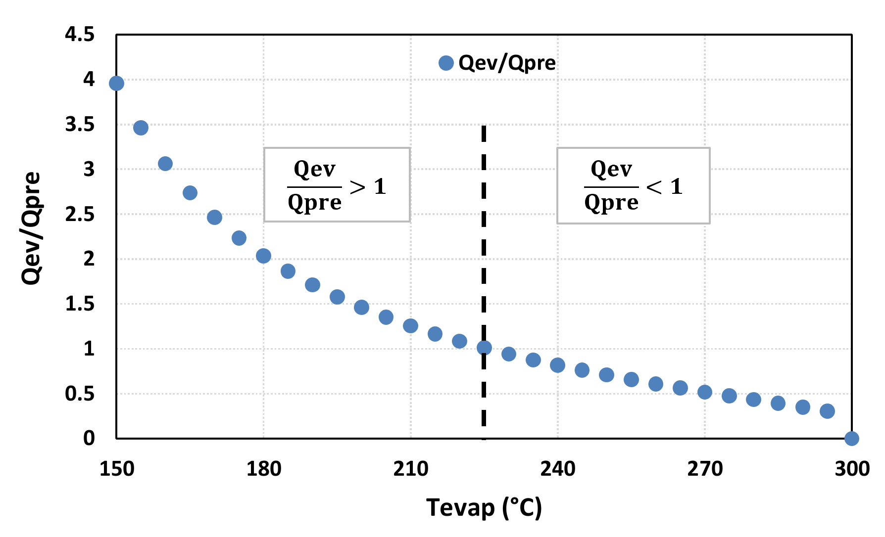
3.1. Evaporation Temperature Sensitivity Analysis

Figure 3 points out a proportional correlation for both the thermal, exergy performances, and mechanical power produced by the turbine when the evaporation temperature increases. The maximum thermal and exergy performances of 15.8% and 35%, respectively, and mechanical power output of 233 kW are reached with the temperature of 300 °C. Indeed, the increasing of the evaporation temperature conduct to recover a higher heat power thus leads to a reduction of the exergy destruction within the evaporator. The higher enthalpy intensity of the output steam leaving the evaporator maximizes the power of the turbine and increases the irreversibility, as shown in Figure 4. Consequently, the exergy destruction in the turbine rises slightly, with the same trend as the destruction of exergy in the condenser. However, the reduction of the evaporator’s exergy destruction is faster so that the total irreversibility of the whole system passes from about 305 to 185 kW for the evaporation temperature ranges of 150 to 300 °C.
In terms of the exergy destruction ratio, the higher value of the evaporation temperature highlights that the exergy destruction is dominated by the condenser and evaporator, with a ratio of 39%. This ratio is about 21% and 1% for the turbine and pump, respectively, as depicted in Figure 5.
Moreover, the increasing of the evaporation temperature points out that the pressure ratio (Pev/Pc) becomes higher from Figure 3b while the ratio Qev/Qpre reduces as represented in Figure 6. The higher pressure ratio risks many stages of the ORC turbine being required, i.e., more expensive. When the evaporation heating is dominated by the preheating step Q e v Q p r e < 1 , this leads to the higher thermal coefficient not being taken advantage of due the evaporation itself (phase change enthalpy). Consequently, a greater area should be implemented in the pre-heater to offset the high heat transfer coefficient of the evaporation step. Thus, the cost of the pre-heater risks being much higher with a direct impact on the energy unit cost ($/kWh). This detail was not developed in the present work and it will be considered in our future investigation. The present work concerns only a preliminary study to point out the potential of an ORC application to produce electricity based on flare gas within the Algerian context.

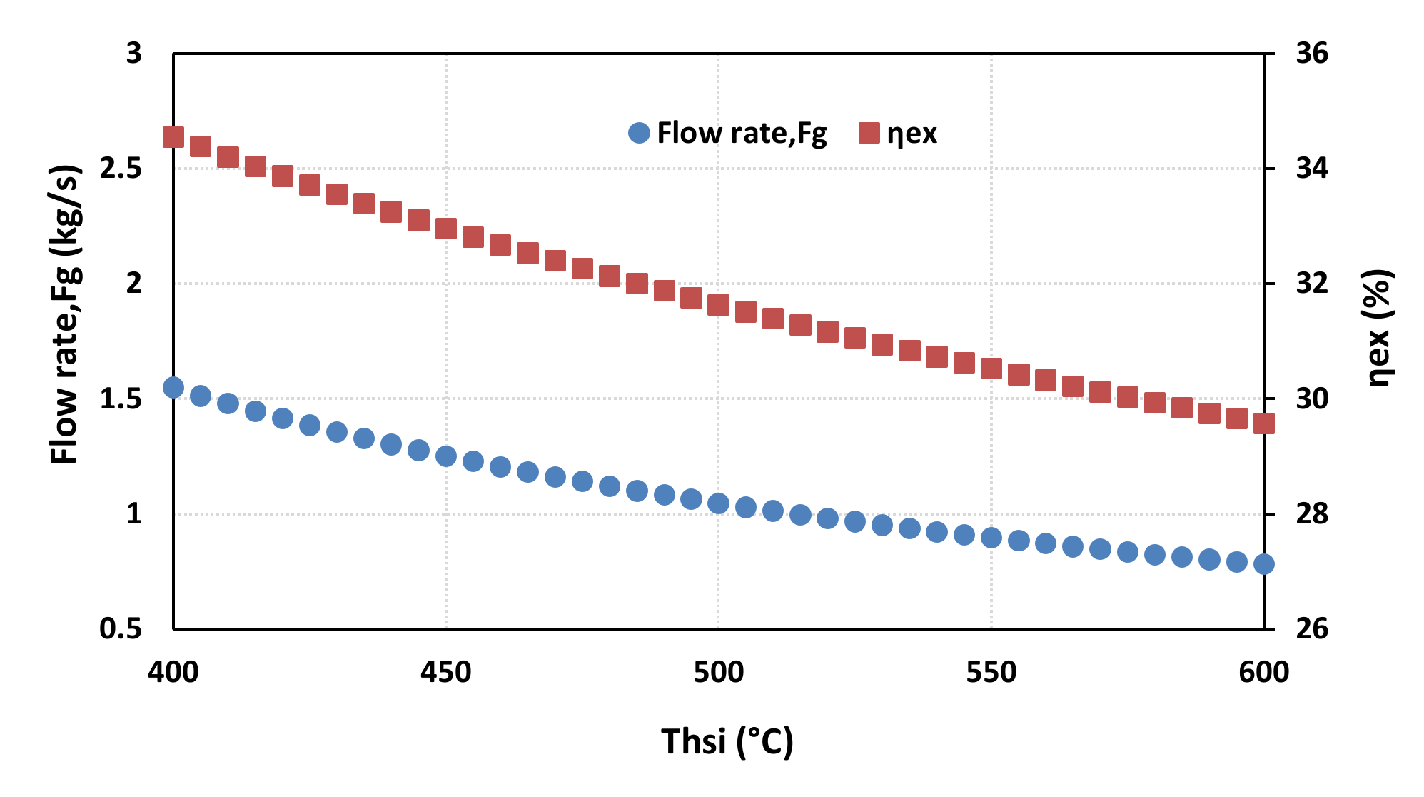
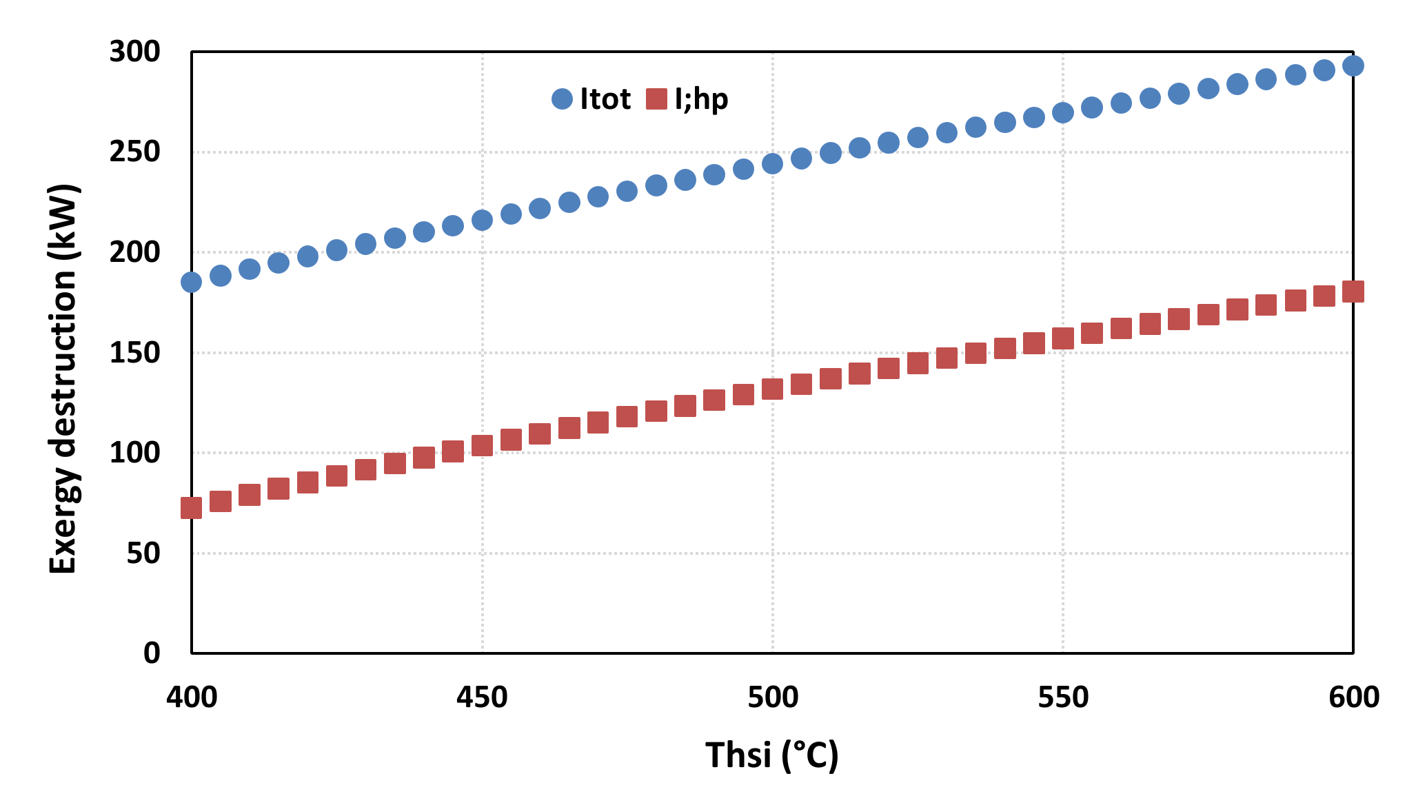
3.2. Heat Source Inlet Temperature Sensitivity Analysis

The sensitivity analysis based on the heat source inlet temperature was performed with a basic ORC configuration (Tev = 300 °C and Tc = 120 °C).
The sensitivity analysis notes that the exergy efficiency and flare gas flow rate vary inversely with an increasing temperature heat source, as shown in Figure 7. The deterioration of the energy performance is mainly due to the generated irreversibility within the evaporator that becomes more important with an increasing heat temperature source as presented in Figure 8. As the ORC cycle is fixed, the total exergy destruction of the ORC system is only and directly affected by irreversibility within the evaporator. It follows the same increasing trends already observed with the evaporator.

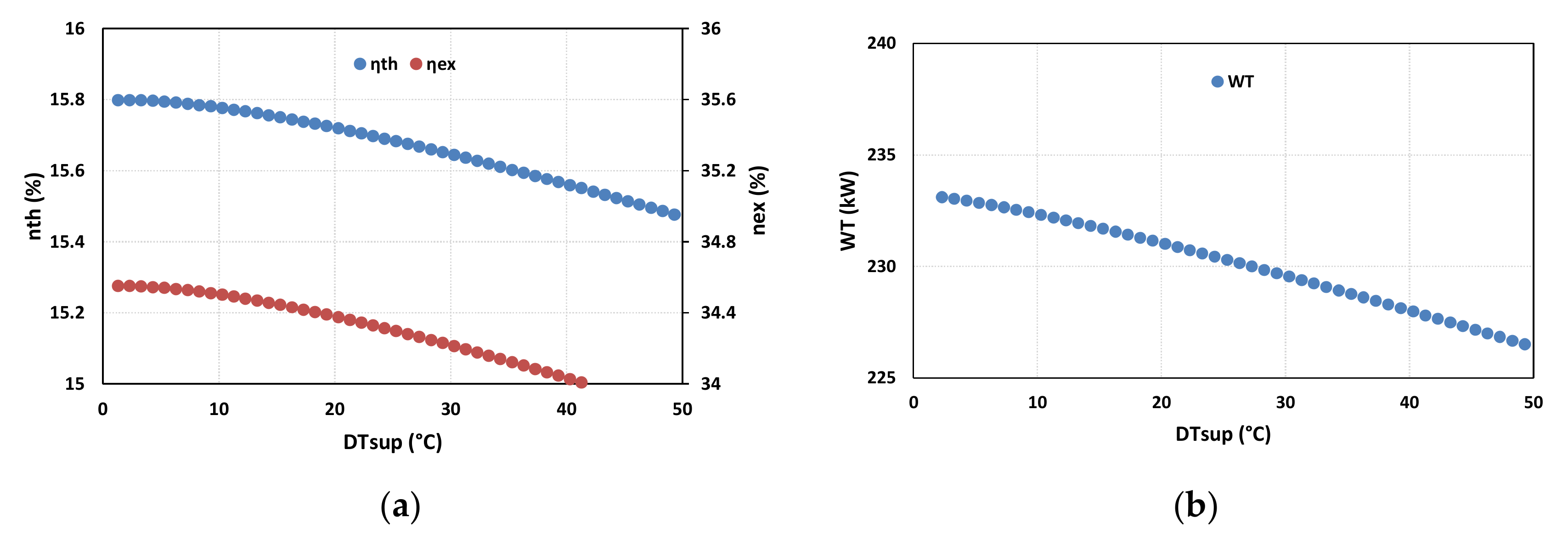
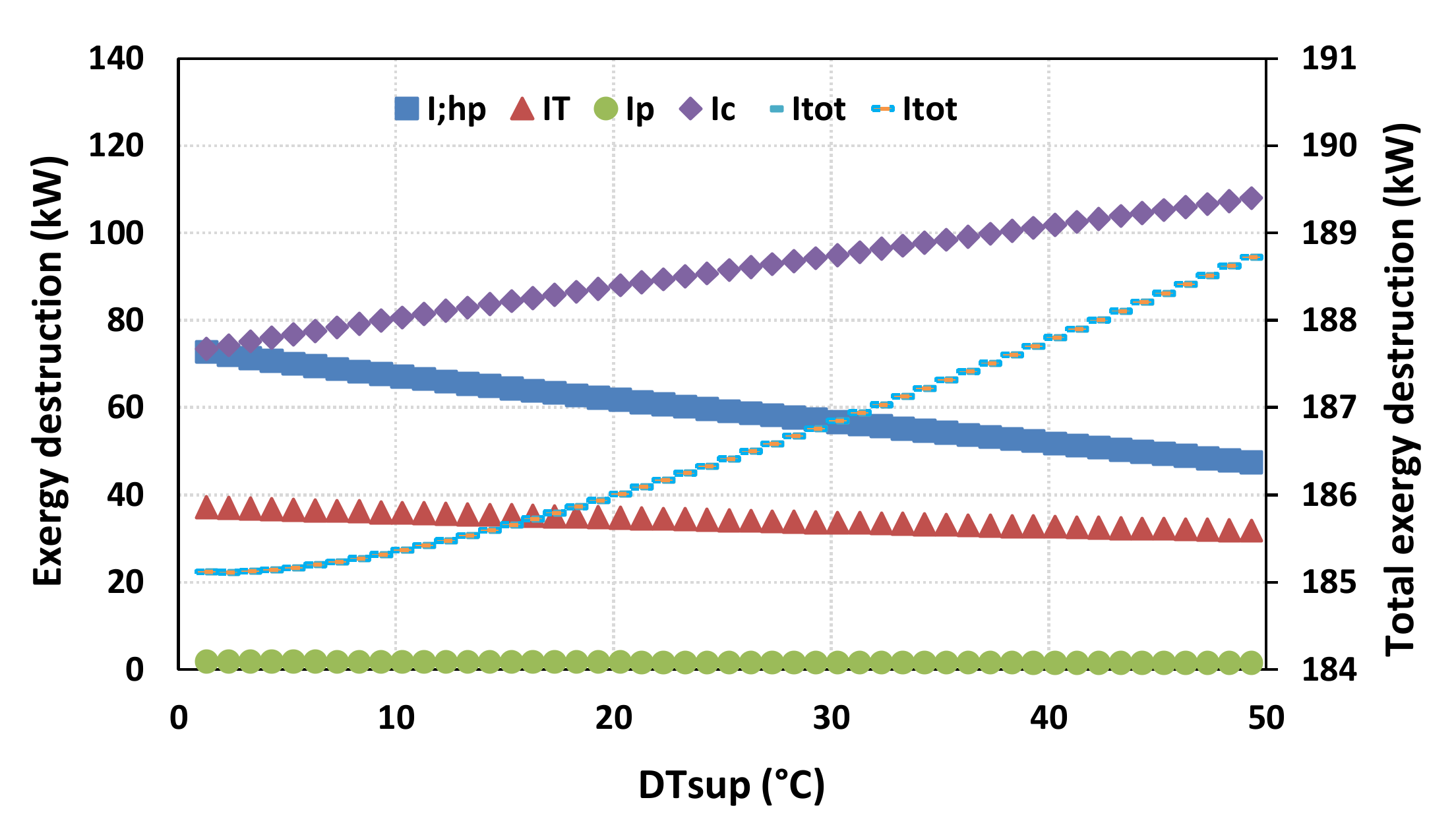
3.3. Super Heating Temperature Sensitivity Analysis

The sensitivity analysis of the super heating temperature was carried out by fixing the inlet heat source temperature, this = 400 °C, for the basic ORC configuration.
The results, as shown in Figure 9, note the reduction of the turbine-generated power when the heat source temperature rises. The super heating step allows a higher recovery amount of the same available thermal power of the heat source. In other terms, the absorbed exergy is improved for the evaporator, decreasing its exergy destruction, as can be observed in Figure 10. However, superheating involves an important exergy destruction within the condenser and then the total exergy of the whole system. Consequently, this fact reduces the exergy performances.

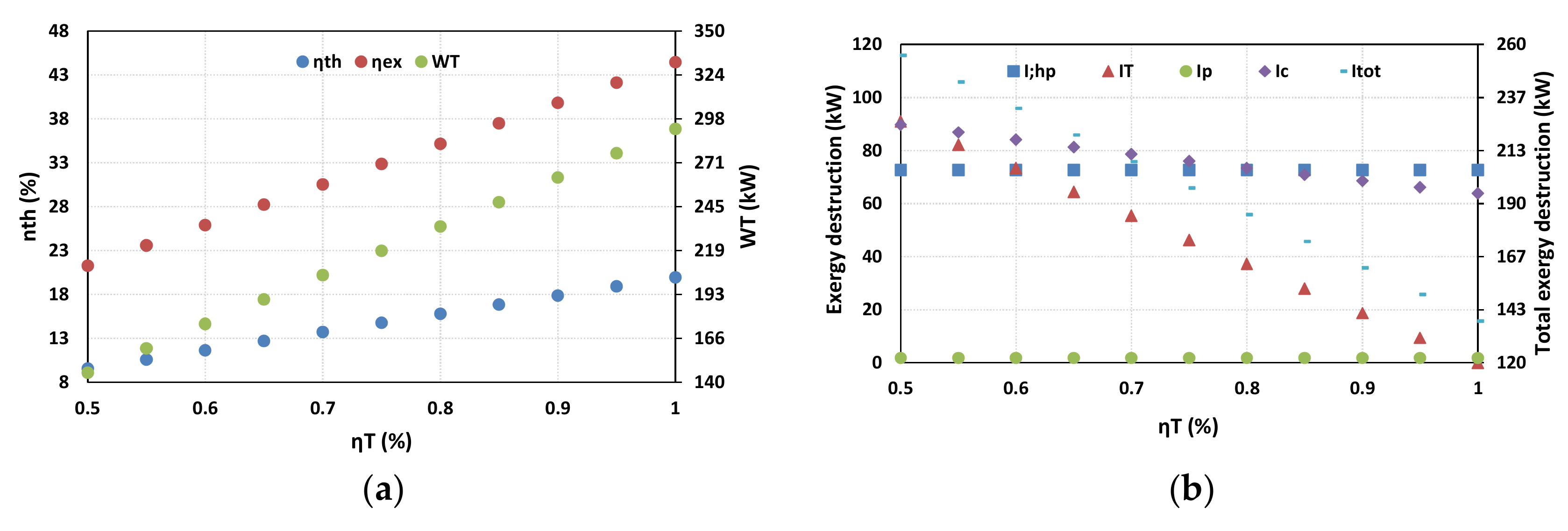
3.4. Turbine Efficiency Sensitivity Analysis

The increasing of the isentropic efficiency of the turbine improves both thermodynamic performances and thus the improvement of the power output of the turbine, as shown in Figure 11a. This is due to diminution of the irreversibility within the turbine, then in the condenser, and consequently the total exergy destruction as observed from Figure 11b. No destruction variation was observed for the high pressure heat exchanger (preheater + evaporator) and for the pump as these compounds are independent of the turbine.

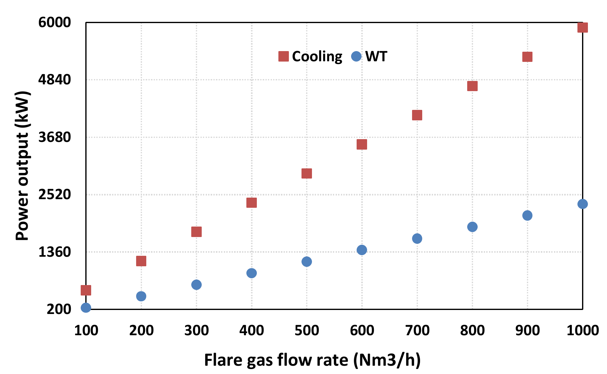
3.5. Integration of Absorption Chiller

The rejected heat at the condenser still presents an important heat potential especially for activating a sorption chiller. A sorption chiller can use either a solid solution—adsorption chiller—or liquid solution in the case of an absorption chiller. As reported by several authors [36,37], the coefficient of performance (COP) and cooling capacity of an absorption chiller are greater than the adsorption technology. Basically, the single effect COP of the absorption chiller ranges from 0.5 to 0.73 for an operating temperature comprised between 60–110 °C. The cooling capacity for commercial applications varies from kW to MW, where the COP ranges from 0.25 to 1.2 depending on both the desired evaporation temperature of the chiller and the inlet temperature [38].
Indeed, the activation of the absorption chiller by the condenser’s rejected heat improves the overall performance of the system and allows it to meet the cooling demand of both petrochemical units and offices initially produced by consuming even gasoline, gases (oil production well), or network electricity in the case of a petrochemical plant. For a fixed COP of 0.5 and absorber feeding temperature (Tcso = 100 °C), the proposed basic ORC system produces electrical power of 233 kW and rejects about 1180 kW, with a thermal performance of 15.8%, thus leading to a cooling capacity of about 590 kW. Therefore, the ORC absorption chiller coupling enhances the performance of the whole system to almost 59%. Depending on the flaring capacity of each plant, a low flaring rate in the petroleum downstream sector compared to the high flaring rate in the upstream sector, the electricity and cooling capacity can vary as depicted in Figure 12. At the maximum flare gas flow rate, the cooling capacity and electrical power output can reach 5.9 and 2.3 MW, respectively.
Concerning the whole exergy performance of the combined systems, this part is not developed as it requires more details and it will be carried in future investigations.

4. Conclusions and Perspectives

The presented paper investigated the implementation of the ORC cycle as a key solution for flare gas waste heat recovery. The study focused on thermodynamic performance studies in terms of energy and exergy balance. This was followed by sensitivity analysis, aiming to highlight the most important parameters with direct impact on the whole system’s performance.
With a fixed temperature of the inlet flare gas, the sensitivity analysis of the evaporation temperature pointed out the diminution of the total destroyed exergy, especially within the evaporator, and subsequently the improvement of the thermodynamic performances and the turbine power output. The maximum evaporation temperature of 300 °C led to higher energy and exergy performances, estimated at 16% and 35%, respectively, while the maximum turbine power reached 230 kW. Moreover, the analysis noted the fact that high temperature heat transfer can be dominated by a preheating step to the detriment of evaporation itself, causing an expensive cost for the evaporator.
The analysis of the inlet’s heat source temperature impact, flare gas, showed a proportional exergy destruction in the evaporator, and then for the whole system, when the heat source temperature was increasing. A direct impact was observed by the reduction of the exergy performance of the ORC system to about 29% when the heat source temperature passed from 400 to 600 °C because of the exergy destruction occurring within the high-pressure heat exchanger.
The impact of the superheating temperature was investigated. As the toluene is a dry fluid, the super heating should be reduced at its minimum. Furthermore, superheating reduces all thermal performances of the systems and induces important exergy destruction, especially in the condenser.
The sensitivity analysis of the turbine efficiency noted the improvement of both thermodynamic performances, total exergy destruction and turbine power output, when increasing the turbine efficiency.
Another solution consisting of the integration of an absorption chiller activated by the condenser’s rejected heat was carried out. The preliminary investigation highlighted the important potential of the ORC-absorption combined system to produce both electricity and cooling with a maximum performance of 59%. This power capacity varies from hundreds of kW in the case of a downstream petroleum application to the MW range for the upstream sector. Such a solution will be investigated deeply in future works to assess accurately the whole exergy performances of the system and to estimate the cost solution and its profitability in the Algerian market.

Author Contributions

Conceptualization, H.S., A.F. and M.F.; methodology, H.S., S.A. and M.F.; software, H.S.; formal analysis, R.F. and M.F.; investigation, H.S. and A.F.; data curation, H.S.; writing—original draft preparation, H.S., A.F., S.A., R.F. and M.F.; writing—review and editing, H.S., A.F., S.A., R.F. and M.F.; visualization, H.S.; supervision, M.F. All authors have read and agreed to the published version of the manuscript.

Funding

This research received no external funding.

Acknowledgments

The authors would like to thank DCRD-SONATRACH and R20-MED for their respective support.

Conflicts of Interest

The authors declare no conflict of interest.

Nomenclature

CpSpecific heat at constant pressure (kJ·kg−1·K−1)
E ˙ x Exergy rate (kW)
hSpecific enthalpy (kJ·kg−1)
I ˙ Destruction of exergy (kW)
m ˙ Mass flow rate (kg·s−1)
PPressure (kPa)
Q ˙ Heat power absorbed (kW)
QSpecific heat (kJ·kg−1)
RGas constant (kJ·kg−1·K−1)
SSpecific entropy (kJ·kg−1·kg−1)
TTemperature (°C)
ΔTsupSuper heating temperature (°C)
ΔTsubSub cooling temperature (°C)
W ˙ Power (kW)
Abbreviations
COPCoefficient Of Performance
FGNFuel Gas Network
FGRFlare Gas Recovery
GTLGas to Liquid
GTWGas To Wire
GWPGlobal Warming Potential
ICEInternal-Combustion Engine
LPGLiquefied Petroleum Gas
NDCNationally Determined Contribution
ODPOzone Depletion Potential
ORCOrganic Rankine Cycle
PNGPiped Natural Gas
SRCSteam Rankine Cycle
VOCVolatile Organic Compound
Subscripts
cCondenser
csi/csoCold sink inlet/outlet
cmCooling medium
evEvaporator
exExergy
fgFlare gas
hHeating
hsi/hsoHeat source inlet/outlet
hpHigh pressure
inInlet
outOutlet
pPump
prePreheator
TTurbine
thThermal
ratRatio
wfWorking fluid
Greek Symbols
ηEfficiency (%)

References

  1. Zolfaghari, M.; Pirouzfar, V.; Sakhaeinia, H. Technical characterization and economicevaluation of recovery of flare gas in various gas-processing plants. Energy 2017, 124, 481–491. [Google Scholar] [CrossRef]
  2. Rahimpour, M.; Jamshidnejad, Z.; Jokar, S.; Karimi, G.; Ghorbani, A.; Mohammadi, A. A comparative study of three different methods for flare gas recovery of Asalooye Gas Refinery. J. Nat. Gas Sci. Eng. 2012, 4, 17–28. [Google Scholar] [CrossRef]
  3. Fawole, O.G.; Cai, X.-M.; MacKenzie, A.R. Gas flaring and resultant air pollution: A review focusing on black Carbon. Environ. Pollut. 2016, 216, 182–197. [Google Scholar] [CrossRef] [PubMed]
  4. Elvidge, C.D.; Zhizhin, M.; Baugh, K.; Hsu, F.-C.; Ghosh, T. Methods for global survey of natural gas flaring from visible infrared imaging radiometer suite data. Energies 2015, 9, 14. [Google Scholar] [CrossRef]
  5. Andersen, R.D.; Assembayev, D.V.; Bilalov, R.; Duissenov, D.; Shutemov, D. Efforts to Reduce Flaring and Venting of Natural Gas World-Wide; Norwegian University of Science and Technology: Trondheim, Norway, 2012. [Google Scholar]
  6. Elvidge, C.D.; Bazilian, M.D.; Zhizhin, M.; Ghosh, T.; Baugh, K.; ChiHsu, F. The potential role of natural gas flaring in meeting greenhouse gas mitigation targets. Energy Strategy Rev. 2018, 20, 156–162. [Google Scholar] [CrossRef]
  7. Knizhnikov, A. Russian Associated Gas Utilization: Problems and Prospects; Annual Report within the Framework of the Project Environment and Energy: International Context. Issue 1. WWF-Russia, Institute of World Economy and International Relations of the Russian Academy of Sciences. 2009. Available online: https://wwf.ru/en/resources/publications/booklets/russian-associated-gas-utilization-problems-and-prospects/ (accessed on 8 March 2020).
  8. Heidari, M.; Ataei, A.; Rahdar, M.H. Development and analysis of two novel methods for power generation from flare gas. Appl. Therm. Eng. 2016, 104, 687–696. [Google Scholar] [CrossRef]
  9. Heydari, M.; Abdollahi, M.A.; Ataei, A.; Rahdar, M.H. Technical and Economic survey on power generation by use of flaring purge gas. In Proceedings of the International Conference on Chemical, Civil and Environmental Engineering (CCEE), Istanbul, Turkey, 5–6 June 2015. [Google Scholar]
  10. Ojijiagwo, E.; Oduoza, C.F.; Emekwuru, N. Economics of gas to wire technology applied in gas flare management. Eng. Sci. Technol. Int. J. 2016, 19, 2109–2118. [Google Scholar] [CrossRef] [Green Version]
  11. Ojijiagwo, E.; Oduoza, C.F.; Emekwuru, N. Technological and economic evaluation of conversion of potential flare gas to electricity in Nigeria. Procedia Manuf. 2018, 17, 444–451. [Google Scholar] [CrossRef]
  12. Anosike, N.B. Thechno-economic Evaluation of Flared Natural Gas Reduction and Energy Recovery Using Gas-To-Wire Scheme. Ph.D. Thesis, Cranfield University, Bedford, UK, 2013. [Google Scholar]
  13. Rahimpoura, M.R.; Jokara, S.M. Feasibility of flare gas reformation to practical energy in Farashband gas refinery: No gas flaring. J. Hazard. Mater. 2012, 209, 204–217. [Google Scholar] [CrossRef]
  14. Hajizadeh, A.; Mohamadi-Baghmolaei, M.; Azin, R.; Osfouri, S.; Heydari, I. Technical and economic evaluation of flare gas recovery in a giant gas refinery. Chem. Eng. Res. Des. 2018, 131, 506–519. [Google Scholar] [CrossRef]
  15. Al-Fehdly, H.; ElMaraghy, W.; Wilkinson, S. Carbon Footprint Estimation for Oil Production: Iraq Case Study for The Utilization of Waste Gas in Generating Electricity. Procedia Cirp. 2019, 80, 389–392. [Google Scholar] [CrossRef]
  16. Adekomaya, O.; Jamiru, T.; Sadiku, R.; Huan, Z.; Sulaiman, M. Gas flaring and its impact on electricity generation in Nigeria. J. Nat. Gas Sci. Eng. 2016, 29, 1–6. [Google Scholar] [CrossRef]
  17. Iora, P.; Bombarda, P.; Gómez Aláez, S.L.; Invernizzi, C.; Rajabloo, T.; Silva, P. Flare gas reduction through electricity production. Energy Sources Part A Recovery Util. Environ. Eff. 2016, 38, 3116–3124. [Google Scholar] [CrossRef]
  18. Tahouni, N.; Gholami, M.; Panjeshahi, M.H. Integration of flare gas with fuel gas network in refineries. Energy 2016, 111, 82–91. [Google Scholar] [CrossRef]
  19. Hasan, M.M.F.; Karimi, I.A.; Avison, C.M. Preliminary synthesis of fuel gas networks to conserve energy & preserve the environment. Ind. Eng. Chem. Res. 2011, 50, 7414–7427. [Google Scholar] [CrossRef]
  20. Comodi, G.; Renzi, M.; Rossi, M. Energy efficiency improvement in oil refineries through flare gas recovery technique to meet the emission trading targets. Energy 2016, 109, 1–12. [Google Scholar] [CrossRef]
  21. Combined Heat and Power (CHP) Partnership, Waste Heat to Power Systems. 2012. Available online: https://www.epa.gov/sites/production/files/2015-07/documents/waste_heat_to_power_systems.pdf (accessed on 8 March 2020).
  22. Aboelwafa, O.; Fateen, S.E.K.; Soliman, A.; Ismail, I.M. A review on solar Rankine cycles: Working fluids, applications, and cycle modifications. Renew. Sustain. Energy Rev. 2018, 82, 868–885. [Google Scholar] [CrossRef]
  23. Zero Routine Flaring by 2030 Initiative. Available online: https://www.worldbank.org/en/programs/zero-routine-flaring-by-2030 (accessed on 23 March 2020).
  24. Li, C.; Hsu, N.C.; Sayer, A.M.; Krotkov, N.A.; Fu, J.S.; Lamsal, L.N.; Lee, J.; Tsay, S.-C. Satellite observation of pollutant emissions from gas flaring activities near the Arctic. Atmos. Environ. 2016, 133, 1–11. [Google Scholar] [CrossRef]
  25. Emam, E.A. Gas flaring in industry: An overview. Pet. Coal 2015, 57, 532–555. [Google Scholar]
  26. Ziyarati, M.T.; Bahramifar, N.; Baghmisheh, G.; Younesi, H. Greenhouse gas emission estimation of flaring in a gas processingplant: Technique development. Process Saf. Environ. Prot. 2019, 123, 289–298. [Google Scholar] [CrossRef]
  27. Andreasen, J.G.; Meroni, A.; Haglind, F. A Comparison of Organic and Steam Rankine Cycle Power Systems for Waste Heat Recovery on Large Ships. Energies 2017, 10, 547. [Google Scholar] [CrossRef] [Green Version]
  28. Lai, N.A.; Wendland, M.; Fischer, J. Working fluids for high-temperature organic Rankine cycles. Energy 2011, 36, 199–211. [Google Scholar] [CrossRef]
  29. Giwa, S.O.; Nwaokocha, C.N.; Kuye, S.I.; Adama, K.O. Gas flaring attendant impacts of criteria and particulate pollutants: A case of Niger Delta region of Nigeria. J. King Saud Univ. Eng. Sci. 2019, 31, 209–217. [Google Scholar] [CrossRef]
  30. NDC-Algeria. Available online: https://www4.unfccc.int/sites/NDCStaging/Pages/Search.aspx?k=algeria (accessed on 23 March 2020).
  31. Le, V.L.; Kheiri, A.; Feidt, M.; Pelloux-Prayer, S. Thermodynamic and economic optimizations of a waste heat to power plant driven by a subcritical ORC (Organic Rankine Cycle) using pure or zeotropic working fluid. Energy 2014, 78, 622–638. [Google Scholar]
  32. Wang, D.; Ling, X.; Peng, H.; Liu, L.; Tao, L. Efficiency and optimal performance evaluation of organic Rankine cycle for low grade waste heat power generation. Energy 2013, 50, 343–352. [Google Scholar]
  33. Molés, F.; Navarro-Esbrí, J.; Peris, B.; Mota-Babiloni, A.; Kontomaris, K.K. Thermodynamic analysis of a combined organic Rankine cycle and vapor compression cycle system activated with low temperature heat sources using low GWP fluids. Appl. Therm. Eng. 2015, 87, 444–453. [Google Scholar]
  34. Michel, F. Génie Energétique Du Dimensionnement des Composants au Pilotage des Systèmes; Collection: Technique et Ingénierie; Dunod: Malakoff, France, 2004; ISBN 978-2-10-070545-0. [Google Scholar]
  35. Bell, H.I.; Wronski, J.; Quoilin, S.; Lemort, V. Pure and pseudo-pure fluid thermophysical property evaluation and the Open-Source thermophysical property library CoolProp. Ind. Eng. Chem. Res. 2014, 53, 2498–2508. [Google Scholar] [CrossRef] [Green Version]
  36. Sarbu, I.; Sebarchievici, C. General reviewof solar-powered closed sorption refrigeration systems. Energy Convers. Manag. 2015, 105, 403–422. [Google Scholar] [CrossRef]
  37. Bataineh, K.; Taamneh, Y. Review and recent improvements of solar sorption cooling systems. Energy Build. 2016, 128, 22–37. [Google Scholar] [CrossRef]
  38. Ebrahimi, M.; Keshavarz, A. CCHP Technology. Combined Cooling, Heating and Power Decision-Making, Design and Optimization; Elsevier: Amsterdam, The Netherlands, 2015; pp. 35–91. [Google Scholar] [CrossRef]
Figure 1. Schematic presentation of an Organic Rankine Cycle ORC waste heat recovery system.
Energies 13 02265 g001
Figure 2. The thermodynamic cycle for the basic ORC system.
Energies 13 02265 g002
Figure 3. Thermodynamic performances (a), and turbine power variation (b) with evaporation temperature evolution.
Energies 13 02265 g003
Figure 4. Exergy destruction with variation of the evaporation temperature.
Energies 13 02265 g004
Figure 5. Exergy destruction ratio with variation of the evaporation temperature.
Energies 13 02265 g005
Figure 6. Evolution of the ratio Qev/Qpre with variation of the evaporation temperature.
Energies 13 02265 g006
Figure 7. Exergy performance and flare gas flow rate with inlet heat source temperature variation.
Energies 13 02265 g007
Figure 8. Exergy destruction with inlet heat source temperature variation.
Energies 13 02265 g008
Figure 9. Thermodynamic performances (a), and mechanical power output variation (b) with superheating temperature evolution.
Energies 13 02265 g009
Figure 10. Exergy destruction with variation of the superheating temperature.
Energies 13 02265 g010
Figure 11. Thermodynamic performances and turbine output (a), and exergy destruction (b) with isentropic turbine efficiency variation.
Energies 13 02265 g011
Figure 12. Cooling and mechanical power output of the combined ORC absorption chiller with variation of the flare gas flow rate.
Energies 13 02265 g012
Table 1. Fitting curve coefficients.
CoefficientValue
A−4.30E−17
B2.75E−13
C−7.22E−10
D9.96E−07
E−7.61E−04
F3.07E−01
G−4.71E+01

