Abstract
A hybrid power system (HPS) is developed for the photovoltaic (PV) powered and tethered multirotor unmanned aerial vehicle (UAV) based on the robot operating system (ROS) and verified using an indoor hardware-in-the-loop (HIL) test. All the processes, including a UAV flight mode change (i.e., takeoff, hovering, and landing) and power flow control (consisting of PV modules, a LiPo battery pack, and a UAV) are completely automated using a combination of Pixhawk 2.1 and the Raspberry Pi 3 Model B (RPi 3B). Once the indoor HIL test starts, (1) the UAV takes off and hovers with a preassigned 10 m altitude at a fixed point and keeps hovering until the voltage drops below 13.4 ; (2) the UAV lands when the voltage drops below 13.4 V, and the hybrid power controller (HPC) starts to charge the LiPo battery pack using the energy from PV modules; and (3) the UAV takes off when the voltage of the battery pack becomes more than 16.8 V, and the procedure repeats from (1). A PV-powered and tethered multirotor UAV using the proposed HPS can fly more safely for a longer time, particularly in an urban area, and so it is competitive to the traditional multirotor type UAV in the sense of both the flight time and the surveillance mission performance.
1. Introduction
Increasing the flight time of an unmanned aerial vehicle (UAV) is getting important as the application of UAVs into 4D (dirty, dangerous, dull, and dear) missions is increasing. A fixed-wing type UAV has, in general, a higher flight endurance compared to the multirotor type UAVs, and thus the former type has been widely applied in surveillance missions that require long endurance. However, the application of using a fixed-wing UAV is typically limited to vast and open plains since it requires a runway for hand or pneumatic launch during takeoff and a safe touch down during landing. Therefore, people have recently started to use multirotor type UAVs, which can perform vertical takeoff and landing (VTOL), mitigating geographic limitations in operations. For continuous aerial surveillance around urban areas with high congestion, the tethered multirotor type UAV is the appropriate choice in the sense of stability and maneuverability.
The main contribution of this paper can be categorized into two parts: (1) a photovoltaic (PV) based hybrid power system (HPS) and (2) a hardware-in-the-loop (HIL) based automatic flight test bench (AFTB). To highlight the main contributions of this manuscript, several previous research works are analyzed in two parts, (1) PV-based HPS and (2) HIL-based AFTB, as follows.
1.1. PV-Based HPS
For even higher flight endurance, there have been approaches to develop a hybrid power system using various combinations of energy sources.
Gong and et al. developed a HPS for a fixed-wing vehicle fusing a fuel cell, a battery pack, and a supercapacitor; they tested it using an HIL-based flight simulation and performed a real flight test [1,2,3]. Lee et al. managed a three-hybrid energy source to power a small long-endurance UAV using an active power management method to ultimately maintain a target state of charge (SOC) of batteries at 45 [4]. Harmon et al. developed the parallel hybrid-electric propulsion system using a rule-based controller and showed that the overall energy consumption could be tremendously reduced [5]. Malaver et al. used the maximum power point (MPPT), a battery charger, and a power path manager using a BQ24030 electronic chip from Texas Instruments Inc. to supply regulated power to a UAV [6,7,8,9]. Meyer et al. developed a power management system for a solar-powered UAV, meeting the nominal system voltage of 22.2 V using PV cells, isolation switches, LiPo batteries, and a power management computer [10]. The Naval Research Laboratory (NRL) developed a hydrogen fuel-cell-based propulsion system by introducing autonomous soaring algorithms with which the UAV flight time is tremendously extended [11,12].
Current challenges of the HPS include (1) increasing energy density; (2) decreasing weight; (3) being operable in the wide system operation voltage, current, and power; (4) possessing a precision state estimation algorithm of all energy sources; and (5) being compatible with the robot operating system (ROS) through the MAVLink on ROS (MAVROS) ROS package.
Here, MAVROS is the “MAVLink extendable communication node for ROS with the proxy for ground control station (GCS)” [13]. MAVLink is a protocol for communicating with UAVs [14]. The MAVROS ROS-package-based MAVLink extendable communication is essential to communicate with ROS-based computers, MAVLink-based autopilots, and MAVLink-based GCSs. With the MAVROS-based hybrid power controller (HPC), which can communicate through MAVLink, we could implement the precision state estimation algorithm of all energy sources for a safe and long mission operation of a UAV.
1.2. HIL-Based AFTB
HIL simulation, also called HILS and HITL, is one of the indoor test methods that is listed as model-in-the-loop (MIL), software-in-the-loop (SIL), processor-in-the-loop (PIL), and HIL. Although all the listed simulation steps are necessary to develop and test real-time embedded systems, we only focus on HIL simulation in this paper.
Akcakoca and et al. presented an SIL- and HIL-based UAV development and verification architecture structured on the ROS, in particular, by using Gazebo, AirSim, and V-REP flight simulators [15]. Lepej and et al. developed a modular-based flexible HIL architecture for the rapid system configuration using ROS [16]. Odelga and et al. developed a ROS and Gazebo-based HIL simulation setup to test algorithms and computational feasibility on a UAV’s hardware platform [17]. Ebeid and et al. presented a survey of existing open-source UAV platform elements that could be utilized for an HIL simulation [18].
None of the above-listed studies developed an HIL-based AFTB to develop a PV-based HPS, and eliminating this gap is the main focus of this paper.
This paper presents the system overview of the HPS, UAV, and GCS in Section 2. Section 3 describes the HPS. Section 4 presents the UAV. Section 5 presents the GCS. Section 6 and Section 7 show the test methods and results. Section 8 shows improvements and comparisons to the existing research works. Lastly, Section 9 concludes the paper.
2. System Overview
The overall system (Figure 1) is composed of an HPS (Section 3), a UAV (Section 4), and a GCS (Section 5). Throughout the paper, each primary system, the HPS, UAV, and GCS, is deeply investigated.
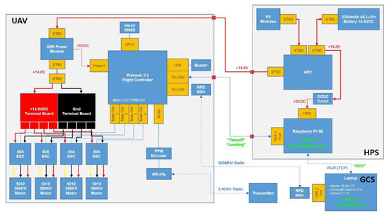
Figure 1.
System overview of unmanned aerial vehicle (UAV), hybrid power system (HPS), and ground control system (GCS).
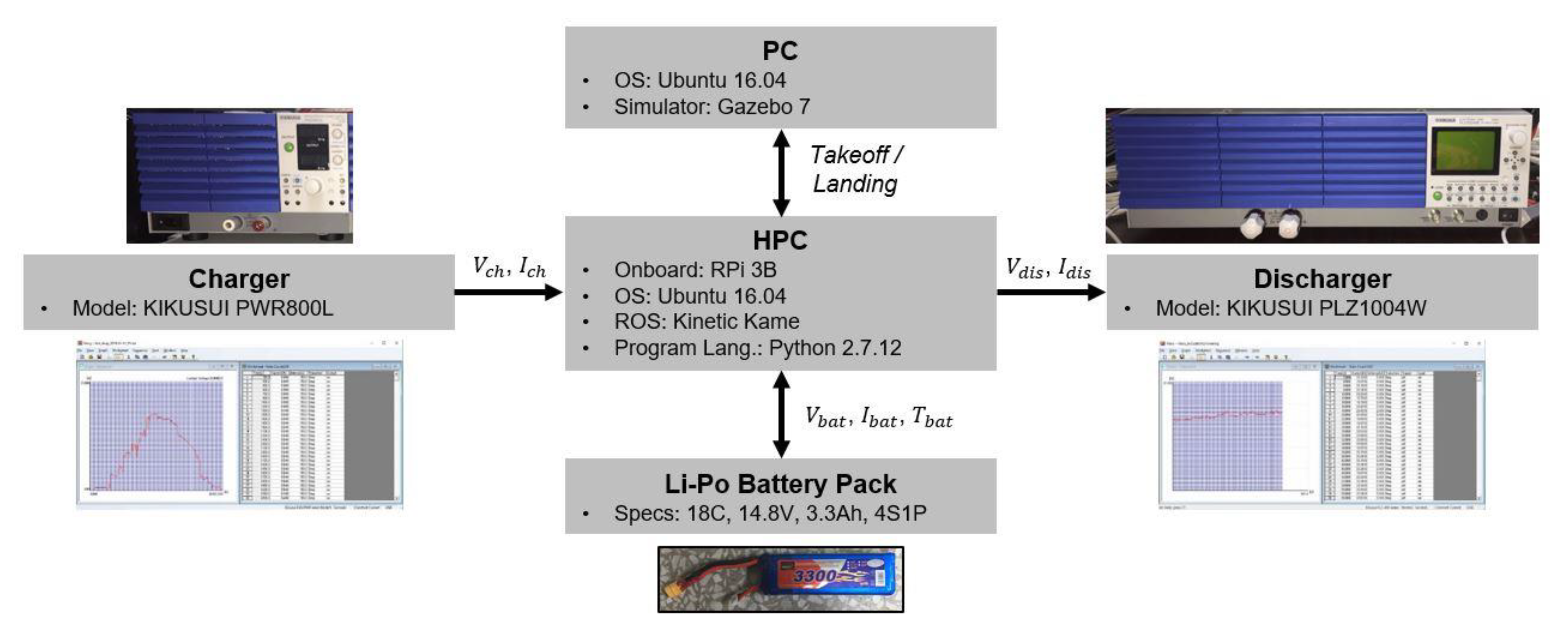
3. HPS
An HPS, which consists of a hybrid power controller (HPC), a PV, and a LiPo battery, is developed to manage the power flow among PV modules, a battery pack, and a UAV.
3.1. HPC
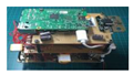
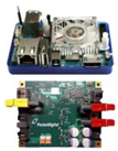
The HPC is the main component of the HPS, and it is necessary to intelligently manage the power flow among PV modules, the battery pack, and the UAV. The HPC is based on a Raspberry Pi 3 Model B (RPi 3B), and so it can communicate with a GCS through Wi-Fi. Detailed specifications and an overview of the HPC are shown in Table 1 and Figure 2. The conceptual electrical interconnection diagram and software are shown in Figure 3 and Figure 4. In particular, we chose the RPi 3B as an onboard computer and Python as the development language since; (1) there is an incomparable number of communities and forums for getting support to solve development issues and (2) the hardware itself is cheap, small, and light enough to be mounted on the small UAV.

Table 1.
Specifications of the hybrid power controller (HPC).
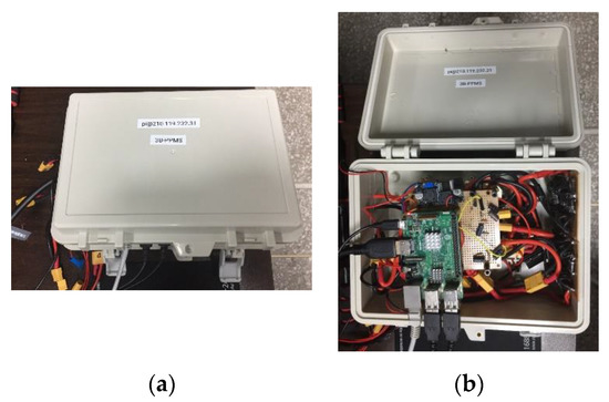
Figure 2.
Overview of the HPC: (a) outside and (b) inside.
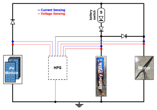
Figure 3.
Conceptual electrical interconnection diagram of the HPC.
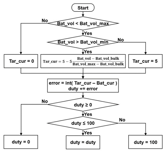
Figure 4.
Conceptual software of the HPC.
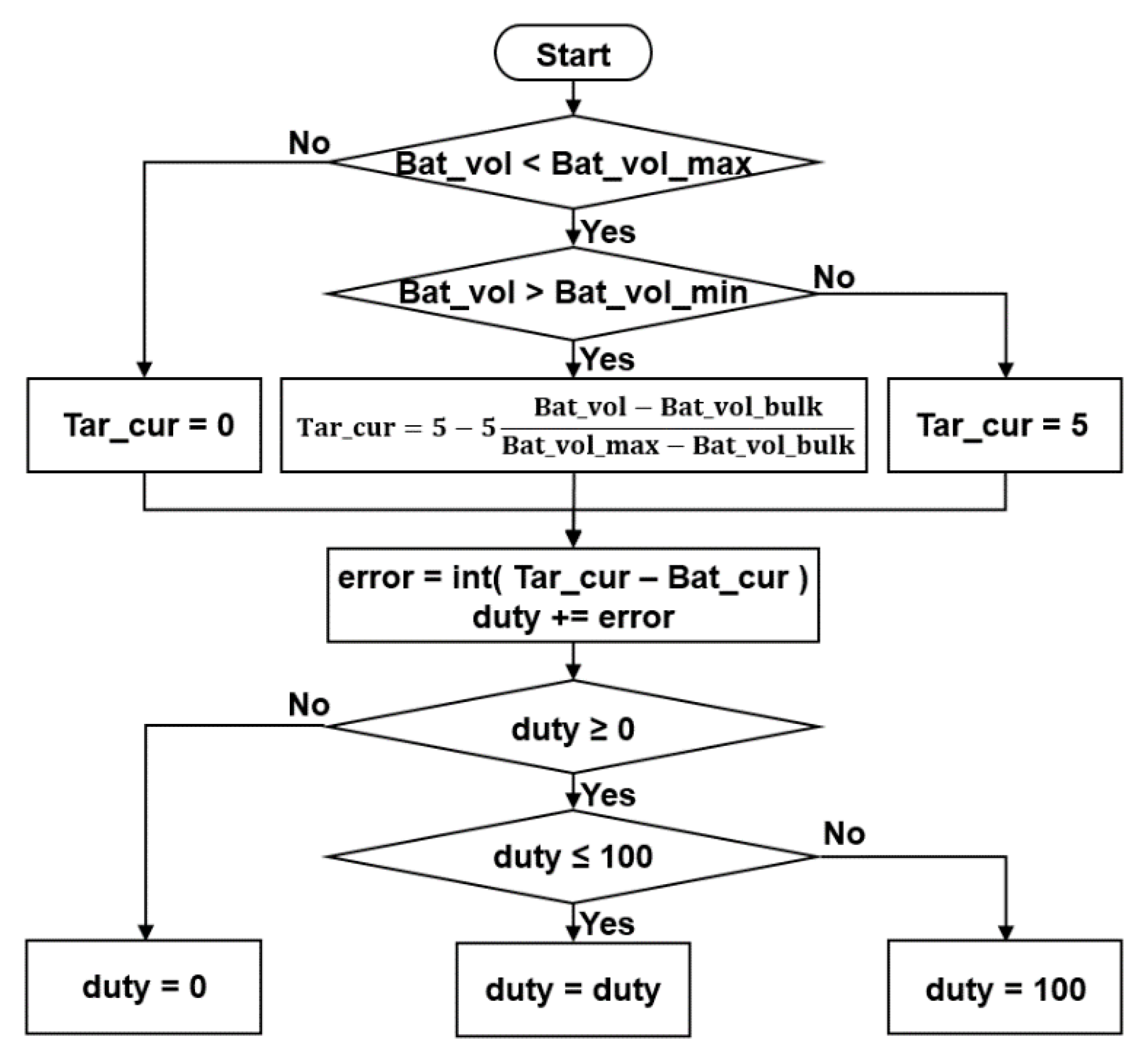
For the transmission control protocol (TCP) setup between the HPS and GCS through Wi-Fi, an RPi 3B located in the HPS runs the PowerManager.py Python code and acts as a client. The structure of the PowerManager.py Python code is shown in Algorithm 1. Here, OCV represents the open circuit voltage.
| Algorithm 1 [CLIENT] PowerManager.py |
|
3.2. PV Module
The PV cells convert light into electricity by the photovoltaic effect as follows: (1) Photons in sunlight are absorbed by semiconducting materials; (2) the absorbed photons excite electrons in the semiconducting materials; (3) excited electrons transmit through a transparent conducting electrode and generate electron–hole pairs; (4) the charge carriers move to cancel out the potential difference; and (5) current flows are captured into either DC or AC.
We used a total of 256 PV cells to form the 32S8P PV-module configuration. One PV module consists of a 32S1P cell configuration, and a total of eight PV modules that are 32S8P are set up to generate about 18 V and 40 A at maximum. Further details of the PV-cell specification (Figure 5) are listed in Table 2.
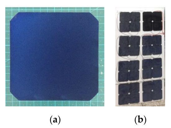
Figure 5.
Overview of the PV (a) cell and (b) module.
Table 2.
Specifications of the photovoltaic (PV) cell.
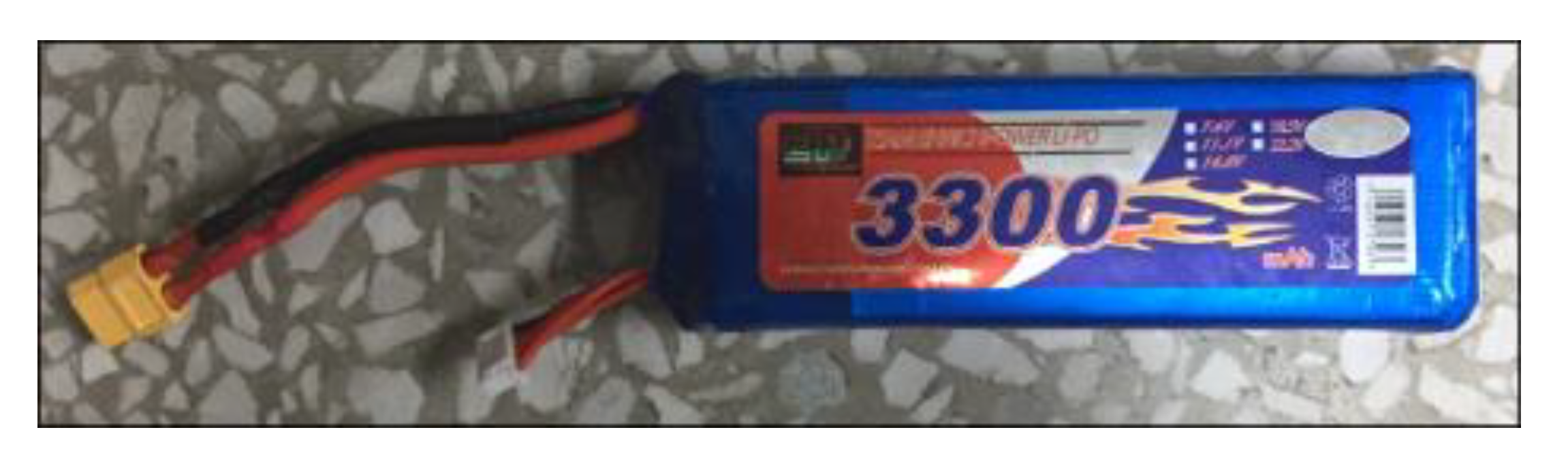
3.3. Battery Pack
We use a LiPo battery pack to give power to the UAV and take power from the PV modules. A LiPo type battery pack is chosen since it has high charging and discharging C-rates compared to the 18,650 prismatic type battery pack. Because of the high charging C-rate, the LiPo battery pack can be quickly charged from the PV module. In addition, due to the high discharging C-rate, the LiPo battery pack can deal with the high current during the takeoff flight mode. Detailed specifications of the LiPo battery pack are shown in Table 3, and the overview is shown in Figure 6.
Table 3.
Specifications of the LiPo battery pack.
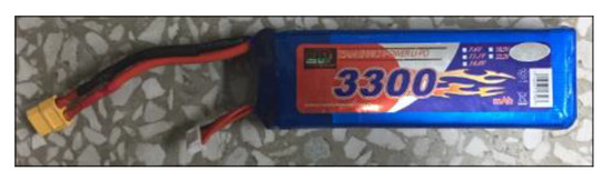
Figure 6.
Overview of the LiPo battery pack.
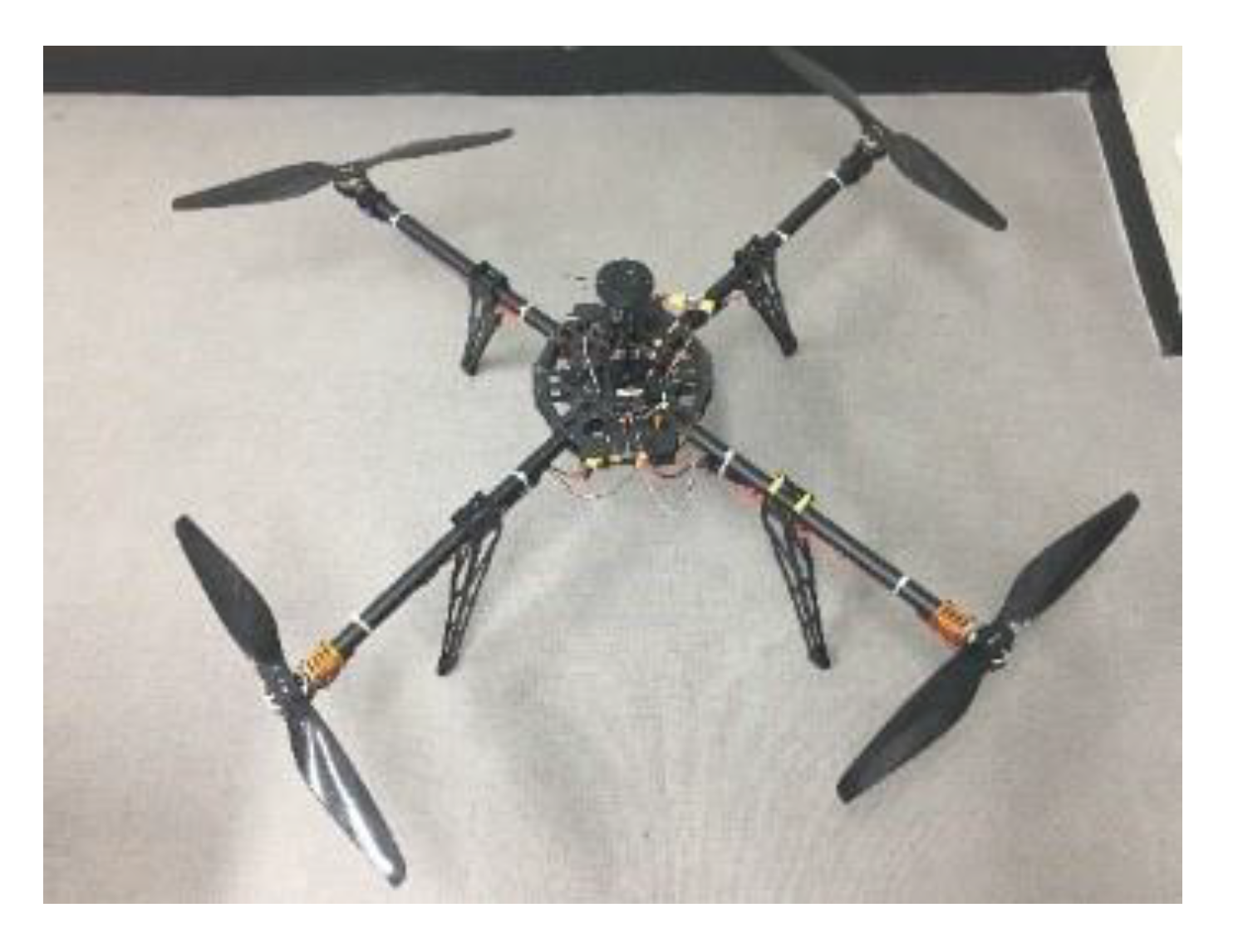
4. UAV
A UAV, which consists of a flight controller (FC), frame, motors, electronic speed controllers (ESC), blades, a GPS, and telemetries, is developed for a continuous surveillance mission. Detailed specifications of the UAV are shown in Table 4, and the overview is shown in Figure 7.
Table 4.
Specifications of the UAV.
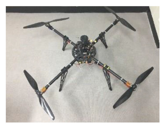
Figure 7.
Overview of the UAV.
5. GCS
A GCS is used mainly to send flight mode commands to the client, which is a HPS, and to monitor the UAV status using QGroundControl (QGC). The GCS is also used for the software-in-the-loop (SIL) and HIL tests. Detailed specifications of the GCS are shown in Table 5, and the overview is shown in Figure 8.
Table 5.
Specifications of the GCS.
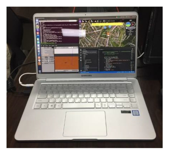
Figure 8.
Overview of the GCS.
For the TCP setup between the GCS and the HPS through Wi-Fi, the GCS runs the HoverSOC.py Python code and acts as a server. The structure of the HoverSOC.py Python code is shown in Algorithm 2.
| Algorithm 2 [SERVER] HoverSOC.py |
|
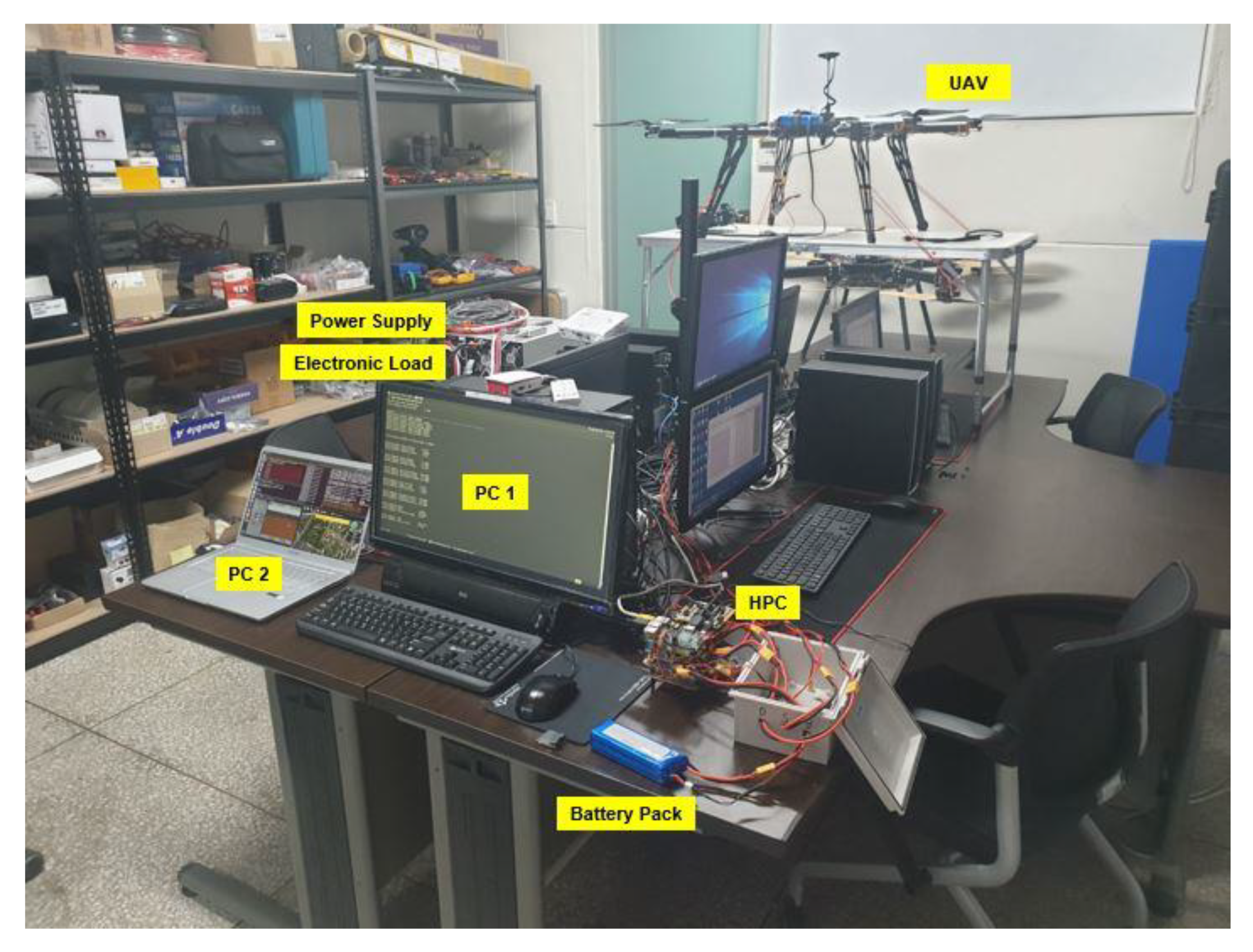
6. Test Method
The HPS was tested and verified through an indoor HIL test (Figure 9 and Figure 10). A charger (Model: KIKUSUI PWR800L) and a discharger (Model: KIKUSUI PLZ1004W) were used to mimic PV modules and a UAV, respectively. In particular, the Gazebo flight simulator was used to perform autonomous flight simulation. Here, the discharger and the Gazebo flight simulator are synchronized so that the discharger starts discharging when the UAV in Gazebo takes off and vice versa.
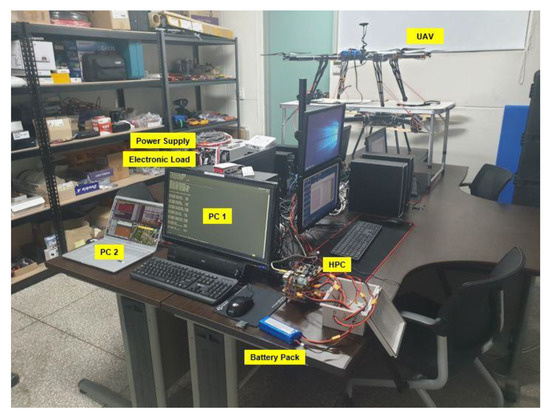
Figure 9.
Indoor experiment.
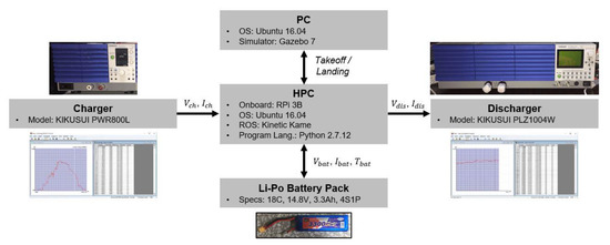
Figure 10.
Indoor hardware-in-the-loop (HIL) test setup.
7. Test Result
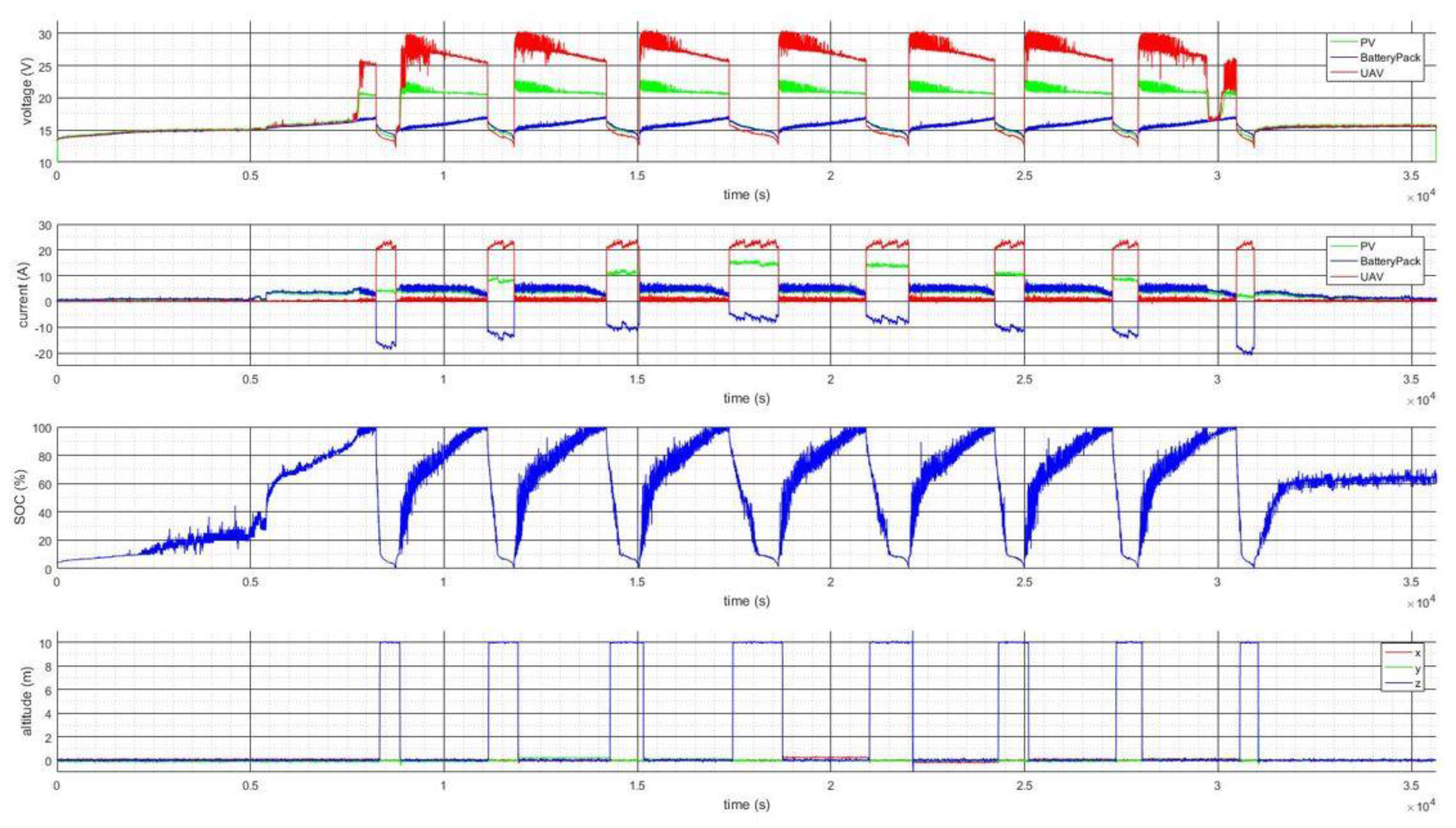
We obtained the current and voltage profiles of the PV modules for 10 h from 08:00 to 18:00 at a schoolyard on 11 November 2019. The stored current and voltage profiles of the PV modules were then used to obtain the battery pack SOC and the UAV altitude data as shown in Figure 11.
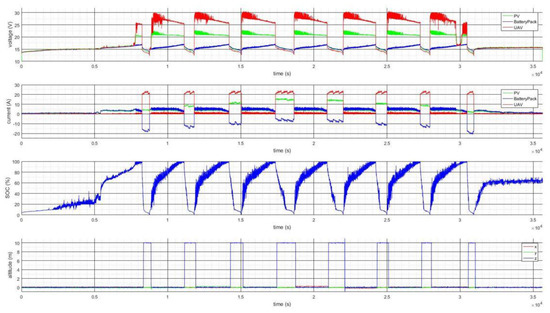
Figure 11.
Indoor HIL test result.
Here, the PV profile is shown as green, the battery pack profile is shown as blue, and the UAV profile is shown as red. The coulomb counting method is used to calculate the SOC. If we carefully look into the battery pack profile, the operating voltage range is between 16.8 and 13.4 V; the charging current is managed to be under 5 A, and the SOC range is between 0% and 100% as we designed it. The UAV altitude operates well between 0 and 10 m.
8. Improvements and Comparisons
The presented HPC developed by Chosun University is unique in the sense that it uses low nominal battery voltage, can be applied to a multirotor type UAV, can deal with the highest power, and lastly uses ROS as shown in Table 6.
Table 6.
Comparison of the HPC boards managing PV, a fuel cell, and a battery pack.
9. Conclusions
We developed a HPC for a tethered solar multirotor UAV (carrying Pixhawk 2.1 and ROS-based RPi 3B) and verified it using indoor HIL tests. Both the automated flight mode change (including takeoff, hovering, and landing) and the power flow control (including PV modules, a LiPo battery pack, and a UAV) were tested and verified.
In the future, a custom HPC printed circuit board (PCB) having a low weight will be manufactured, installed, and tested on a VTOL-type UAV to demonstrate its effectiveness in the aspect of flight duration.
Funding
This work was supported by the Jeonnam Technopark (JNTP) through the project B0080802000131.
Conflicts of Interest
The author declares no conflict of interest.
References
- Gong, A.; MacNeill, R.; Verstraete, D.; Palmer, J.L. Analysis of a Fuel-Cell/Battery/Supercapacitor Hybrid Propulsion System for a UAV using a Hardware-in-the-Loop Flight Simulator. In Proceedings of the AIAA/IEEE Electric Aircraft Technologies Symposium, Cincinnati, OH, USA, 9–11 July 2018; pp. 1–17. [Google Scholar]
- Gong, A.; Verstraete, D. Evaluation of a Hybrid Fuel-Cell based Propulsion System with a Hardware-in-the-Loop Flight Simulator. In Proceedings of the 23rd International Society for Air Breathing Engines, Petersfield, UK, 3–8 September 2017; pp. 1–17. [Google Scholar]
- Gong, A.; Palmer, J.L.; Verstraete, D. Flight Test of a Fuel-Cell/Battery/Supercapacitor Triple Hybrid UAV Propulsion System. In Proceedings of the 31st Congress of the International Council of the Aeronautical Sciences, Belo Horizonte, Brazil, 9–14 September 2018; pp. 1–10. [Google Scholar]
- Lee, B.; Kwon, S.; Park, P.; Kim, K. Active Power Management System for an Unmanned Aerial Vehicle Powered by Solar Cells, a Fuel Cell, and Batteries. IEEE Trans. Aerosp. Electron. Syst. 2014, 50, 3167–3177. [Google Scholar] [CrossRef]
- Harmon, F.G.; Frank, A.A.; Chattot, J. Conceptual Design and Simulation of a Small Hybrid-Electric Unmanned Aerial Vehicle. J. Aircr. 2006, 43, 1490–1498. [Google Scholar] [CrossRef]
- Malaver, A.; Motta, N.; Corke, P.; Gonzalez, F. Development and Integration of a Solar Powered Unmanned Aerial Vehicle and a Wireless Sensor Network to Monitor Greenhouse Gases. Sensors 2015, 15, 4072–4096. [Google Scholar] [CrossRef] [PubMed]
- Bq2403x Single-Chip Charge and System Power-Path Management IC (bqTINYTM). Available online: https://goo.gl/Tr6A74 (accessed on 9 March 2020).
- Smith, N. Dynamic Power Path Management Simplifies Battery Charging from Solar Panels; Texas Instruments: Dallas, TX, USA, 2006; pp. 1–5. [Google Scholar]
- Malaver, A.; Matteocci, F.; Carlo, A.D.; Corke, P.; Motta, N. Remote Monitoring of Outdoor Performance of Low Scale Dye Sensitized Solar Cells for Nanosensors Nodes. In Proceedings of the International Conference on Remote Sensing and Data, Harbour Plaza Resort City, Hong Kong, China, 2–3 July 2011; pp. 1–5. [Google Scholar]
- Meyer, J.; Plessis, J.; Ellis, P.; Clark, W. Design Considerations for a Low Altitude Long Endurance Solar Powered Unmanned Aerial Vehicle. In Proceedings of the IEEE AFRICON, Windhoek, South Africa, 26–28 February 2007; pp. 1–7. [Google Scholar]
- Edwards, D.J. Integrating Hydrogen Fuel Cell Propulsion and Autonomous Soaring Techniques. In Proceedings of the AIAA SciTech Forum, Kissimme, FL, USA, 8–12 January 2018; pp. 1–16. [Google Scholar]
- Swider-Lyons, K.E.; Stroman, R.O.; Gould, B.D.; Rodgers, J.A.; MacKrell, J.; Schuette, M.; Page, G. Hydrogen Fuel Cells for Small Unmanned Air Vehicles. In Proceedings of the ECS Transactions, Los Angeles, CA, USA, 10–13 November 2014; pp. 963–972. [Google Scholar]
- MAVROS. Available online: http://wiki.ros.org/mavros (accessed on 9 March 2020).
- MAVLink Developer Guide. Available online: https://mavlink.io/en/ (accessed on 9 March 2020).
- Akcakoca, M.; Atici, B.M.; Gever, B.; Oguz, S. A Simulation-Based Development and Verification Architecture for Micro UAV Teams and Swarms. In Proceedings of the AIAA SciTech Forum, Sam Diego, CA, USA, 7–11 January 2019; pp. 1–15. [Google Scholar]
- Lepej, P.; Santamaria-Navarro, A.; Sola, J. A Flexible Hardware-in-the-Loop Architecture for UAVs. In Proceedings of the International Conference on Unmanned Aircraft Systems, Miami, FL, USA, 13–16 June 2017; pp. 1751–1756. [Google Scholar]
- Odelga, M.; Stegagno, P.; Bulthoff, H.H.; Ahmad, A. A Setup for Multi-UAV Hardware-in-the-Loop Simulations. In Proceedings of the Workshop on Research, Education and Development of Unmanned Aerial Systems, Cancun, Maxico, 23–25 November 2015; pp. 204–210. [Google Scholar]
- Ebeid, E.; Skriver, M.; Terkildsen, K.H.; Jensen, K.; Schultz, U.P. A Survey of Open-Source UAV Flight Controllers and Flight Simulators. Microprocess. Microsyst. 2018, 61, 11–20. [Google Scholar] [CrossRef]
- Gang, B.G.; Kwon, S. Design of an Energy Management Technique for High Endurance Unmanned Aerial Vehicles Powered by Fuel and Solar Cell Systems. Int. J. Hydrogen Energy 2018, 43, 9787–9796. [Google Scholar] [CrossRef]
- Stroman, R.; Edwards, D. The Hybrid Tiger: A Long Endurance Solar/Fuel Cell/Soaring Unmanned Aerial Vehicle. In Proceedings of the 2018 U.S. Department of Energy (DOE) Hydrogen and Fuel Cells Program Annual Merit Review and Peer Evaluation Meeting, Washington, DC, USA, 13–15 June 2018; pp. 1–14. [Google Scholar]


© 2020 by the author. Licensee MDPI, Basel, Switzerland. This article is an open access article distributed under the terms and conditions of the Creative Commons Attribution (CC BY) license (http://creativecommons.org/licenses/by/4.0/).