Article

Photovoltaic Lithium-ion Battery with Layer-Structured Li2MnIII0.2MnIV0.8O2.9 Thin Film Chemically Fabricated for Cathodic Active Material

1
Applied Chemistry and Chemical Engineering Program, Graduate School, Kogakuin University, Tokyo 192-0015, Japan
2
Department of Applied Physics, School of Advanced Engineering, Kogakuin University, Tokyo 192-0015, Japan
*
Author to whom correspondence should be addressed.
Energies 2020, 13(6), 1486; https://doi.org/10.3390/en13061486
Submission received: 15 February 2020 / Revised: 13 March 2020 / Accepted: 17 March 2020 / Published: 21 March 2020
(This article belongs to the Section A2: Solar Energy and Photovoltaic Systems)

Abstract

:
Dilithium manganese oxide (LMO) thin film was newly fabricated as an active material on a fluorinated-tin-oxide pre-coated glass electrode by a wet process. A stable LMO precursor solution was developed through the reaction of lithium and manganese acetates with butylamine in ethanol. A spin-coated precursor film was heat-treated at 500 °C in air for 0.5 h. The X-ray diffraction pattern indicates that the resultant film consists of layer-structured LMO crystals. The X-ray photoelectron spectra of LMO thin film suggests that the ratio of Mn3+/Mn4+ is 1/4, and the chemical formula can be expressed as Li2MnO2.9. A device was assembled with O-deficient LMO and TiO2 thin films as each active material, along with an electrolytic solution involving LiPF6. The charging voltages (2.67 and 1.45 V) of this device were recorded by applying a constant current of 0.2 mA and using 1-sun irradiation with no external power supply, respectively. The voltages delivered by this cobalt-free device were 0.63 and 0.13 V higher, respectively, than the corresponding device assembled with lithium cobalt oxide as a cathodic active material.

1. Introduction

Recently, we reported on the fabrication of a new photovoltaic lithium-ion battery (PV-LIB) with LiCoO2 (LCO) and titania thin films for cathodic and anodic active materials, respectively. These materials were fabricated on a fluorinated-tin-oxide (FTO) pre-coated glass substrate using the molecular precursor method (MPM) [1]. The MPM is one of the wet chemical processes, which was developed in our group for fabricating thin films of various metals, metal oxides, and phosphate compounds [1,2,3,4,5,6,7,8,9,10,11,12,13]. This method has many advantages, such as excellent stability, homogeneity, miscibility, and compatibility.
An efficient lithium-ion battery (LIB) using LCO, which is widely used and also assembled in the previous PV-LIB, was first reported by Mizushima et al. in 1980 [14]. Various materials have been studied as an alternative for LCO because cobalt is a rare metal element. Kalyani et al. reported in 1999 that dilithium manganese (IV) oxide (Li2MnO3, LMO) is an electrochemically active material, and offered suggestions for the removal/insertion processes of lithium-ion [15]. This study and other studies have given increased attention to LMO, which has a layered crystal structure analogous to LCO, as one of the most promising candidates for the cathodic active material of LIB [15,16,17,18,19,20]. The LMO thin films have been fabricated using radiofrequency sputtering with post-annealing at 850 °C in air, and pulsed laser deposition with a substrate temperature higher than 650 °C during deposition [16,17,18,19,20]. In these physical vapor depositions, the vacuum system and associated maintenance require high costs [21]. There is currently no report, however, on LMO thin film fabrication using the low-cost wet-chemical process.
We report on the fabrication of LMO thin film on an FTO pre-coated glass substrate using a solution-based process, and the corresponding application to cobalt-free PV-LIB.

2. Materials and Methods

2.1. Materials

Lithium acetate, butylamine, 2-propanol, titania molecular precursor solution (Ti4+ = 0.5 mmol g1), and molecular sieves 4A were purchased from FUJIFILM Wako Pure Chemical Corporation, Osaka, Japan. Manganese (II) acetate was purchased from Alfa Aesar, Lancashire, United Kingdom. The LiPF6 solution of 1 mol L1 in ethylene carbonate/dimethyl carbonate (1:1 by volume) was purchased from KISHIDA CHEMICAL Co. Ltd., Osaka, Japan. Ethanol was purchased from Ueno Corporation, Osaka, Japan, and was dried with molecular sieves 4A before use. Other materials were used without further purification. An FTO pre-coated soda-lime glass substrate was purchased from AGC Inc., Tokyo, Japan. The substrates with dimensions of 20 × 33 × 1.8 mm3 were prepared and ultra-sonicated in 2-propanol for 0.5 h, and then dried in a drying oven at 70 °C before use.

2.2. Preparation of LMO Precursor Solution

The LMO precursor solution (SLMO) was prepared by mixing 0.27 g (4.0 mmol) of lithium acetate, 0.35 g (2.0 mmol g) of manganese acetate, and 1.79 g (24.0 mmol) of butylamine in 10 g of ethanol with mechanical stirring at 25 °C for three h. The concentration of Li+ and Mn2+ ions was adjusted to 0.33 and 0.17 mmol g−1, respectively.

2.3. Coating and Heat-treating Procedures

Before the coating process, FTO pre-coated glass substrates were partially covered with masking tape to limit the size of the coating area to 20’ 20 mm2. The precursor films of LMO and titania on the FTO pre-coated glass substrates were formed by spin-coating each 50 μL of SLMO and commercially available titania precursor solution at 25 °C. A two-step process (first step at 500 rpm for 5 s, and second step at 2000 rpm for 30 s) was used in the spin-coating method. The precursor films obtained by pre-heating in a drying oven at 70 °C for 10 min were heat-treated in the air at 500 °C for 0.5 h. The resultant thin films were denoted as FLMO and FTitania, respectively. In order to determine the crystal structure of LMO, another thin film of three-layered F’LMO was also prepared using the same procedure from the spin-coated precursor film on FLMO using SLMO repeatedly.

2.4. Crystal Structure of Thin Films

The crystal structure of FLMO, F’LMO, and FTitania were determined using X-ray diffraction (XRD) with a SmartLab X-ray diffractometer (Rigaku Corporation, Tokyo, Japan). This diffractometer utilized a Cu-Kα radiation source at a power of 45 kV and 200 mA. Parallel beam optics at an incidence angle 0.3° was used in the 2θ range of 10–80°. The scanning step width was 0.05°, and the speed was 5° min−1.

2.5. Surface Morphology and Thin Film Thickness

The surface morphology and cross-sectional images of FLMO, F’LMO, and FTitania were observed by a field-emission scanning electron microscopy (FE-SEM) using JSM-6701F (JEOL Ltd., Tokyo, Japan) at an accelerating voltage of 5 kV. The average grain size of each thin film was calculated from ten randomly selected and different grains. The film thickness was determined as the average height at ten different positions of each cross-sectional image.

2.6. Chemical Characterization of Thin Films

X-ray photoelectron spectroscopy (XPS) spectra of FLMO were measured by a JPS-9030 spectrometer (JEOL Ltd., Tokyo, Japan) using a non-monochromatic Al-Kα X-ray radiation (1486.6 eV) and a step width of 0.1 eV. The FLMO was sputtered with Ar ions at an acceleration voltage of 300 V and a current density of 5.1 mA cm−2 for 60 s before XPS analysis. The binding energies of the XPS spectra data were corrected with reference to the C 1 s peak at 285.0 eV. After binding energy correction, the Shirley-type baseline and peak positions were calculated using Origin 2018 software (OriginLab Corporation, MA, USA).
The Li 1s/Mn 3p and Mn 3s peaks were deconvoluted by a nonlinear least-square method with the use of the Voigt function. The peak fitting converged when the difference of reduced chi-square (χ2), which is the χ2 value divided by the number of degrees of freedom, reached the tolerance value of 10−9. χ2 is represented by the following Equation (1), where IO is the observed spectral intensity and IC is the calculated value of the intensity obtained by the fitting:
χ 2 = ( I o I C ) 2
The Li/Mn ratio of FLMO was evaluated from the peak areas of Li 1s and Mn 2p3/2 in the XPS spectra using relative sensitivity factors obtained from SpecSurf software (JEOL Ltd., Tokyo, Japan), and can be represented by the following Equation (2):
Li / Mn   ratio = p e a k   a r e a   o f   L i   1 s / relative   sensitivity   factor   of   Li   1 s   for   Al   K α : 0.2504 peak   area   of   Mn   2 p 3 / 2 relative   sensitivity   factor   of   Mn   2 p 3 / 2   for   Al   K α : 36.1170
The average oxidation state (AOS) of Mn was obtained using the linear correlation between AOS of Mn and ΔE, which can be expressed by the following Equation (3) [22], where ΔE represents the magnitude of the Mn 3s splitting. The value was calculated by the energy difference between the deconvoluted peaks assignable to Mn 3s level:
AOS = 8.956 − 1.126·ΔE

2.7. Charge/discharge Cyclic Test on the Assembled Device

The electrodes FLMO, F’LMO, and FTitania were assembled into a sealed sandwich-type device, with an electrolytic solution utilizing LiPF6 (Scheme 1). Teflon sheets (Taisei Kagaku Co., Ltd., Tokyo, Japan) and double-coated adhesive polyester tapes (Nitto Denko Corporation, Osaka, Japan) were used as a spacer with a thickness of 200 μm between the electrodes.
The charge/discharge cyclic test of the device was performed in accordance with the previously reported procedures [1,12]. In the charge/discharge current-insertion mode of 30 cycles at 60 s intervals, a constant current of 0.2 mA was applied during charging and then self-discharged. The voltage change of the device was recorded by a DC voltage source/monitor 6241 A (ADC Co., Ltd., Saitama, Japan). In the light-irradiation mode, the repeated 1-sun irradiation using a Lax-Cute solar simulator (Asahi Spectra Co., Ltd., Tokyo, Japan) and self-discharge in dark conditions was performed 30 times at 60 s intervals. The voltage during the cyclic test by light-irradiation was measured by a digital multimeter VOAC7523H (IWATSU ELECTRIC Co., Ltd., Tokyo, Japan).

3. Results

3.1. XRD Patterns of FLMO, F’LMO, and FTitania

Figure 1a shows the XRD pattern of FLMO and F’LMO. Three peaks at 2θ = 18.8, 21.4, and 44.7° for both FLMO and F’LMO and three peaks at 2θ = 37.1, 59.1, and 65.4° for F’LMO are assignable to the (001), (110), (−132), (131), (132), and (060) crystal phases of layered rock-salt Li2MnO3 (ICDD card No. 01-084-1634), respectively. The additional twelve peaks at 2θ = 26.6, 34.0, 38.0, 39.1, 42.7, 51.8, 54.9, 61.9, 64.8, 66.0, 71.2, and 78.7°, which can be ascribed to SnO2 phases (ICDD card No. 00-041-1445) in FTO, are observed. The XRD pattern of FTitania is also shown in Figure 1b. Five peaks at 2θ = 25.4, 48.1, 62.9, 70.2, and 75.1° are assignable to (101), (200), (204), (220), and (215) phases of anatase (ICDD card No. 00-064-0863), respectively. The additional nine peaks at 2θ = 34.0, 38.0, 51.8, 54.9, 61.9, 64.8, 66.0, 71.2, and 78.7°, which can be ascribed to SnO2 in FTO, were also observed.

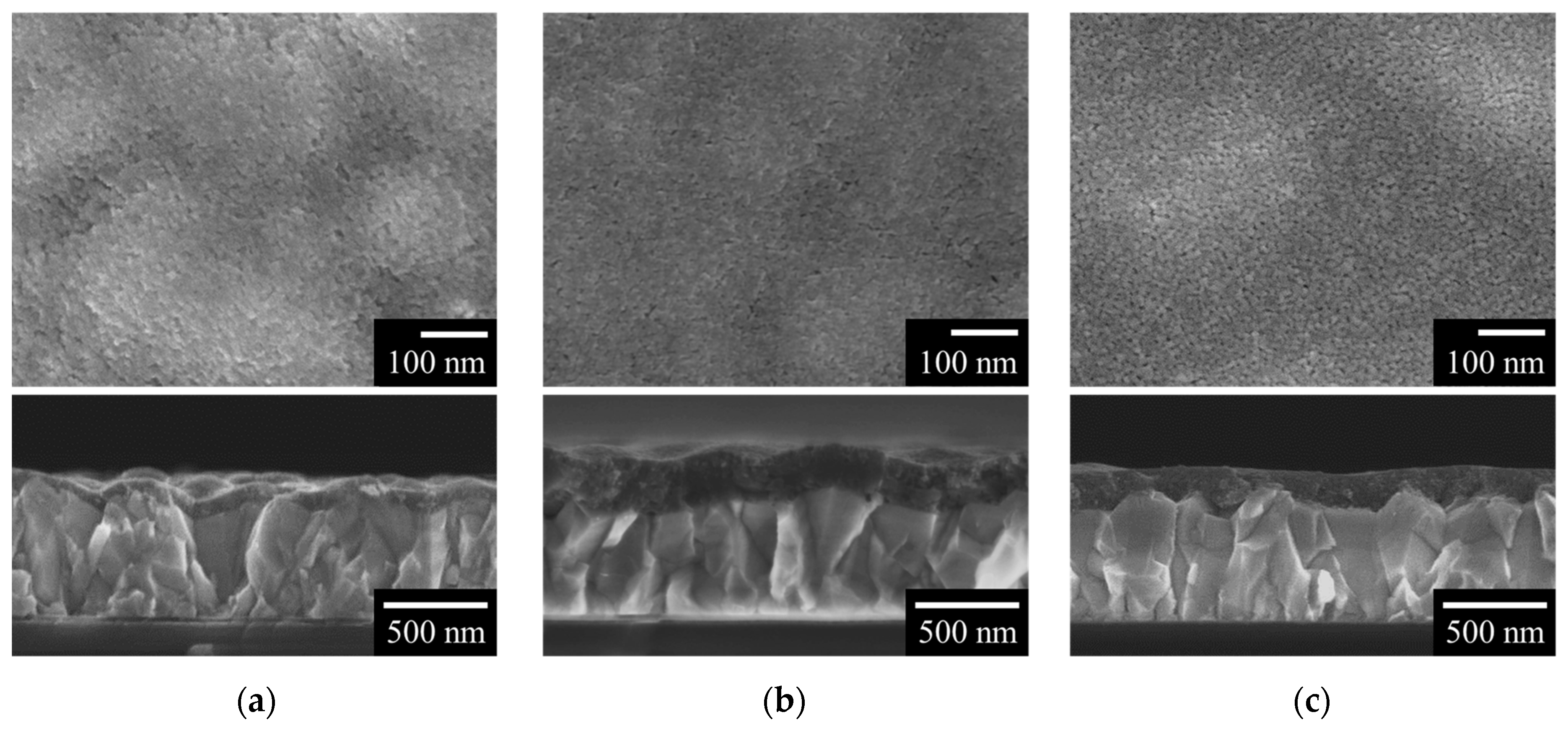
3.2. Surface Morphology and Film Thickness of FLMO, F’LMO, and FTitania

Figure 2 shows the surface and cross-sectional images of (a) FLMO, (b) F’LMO, and (c) FTitania, observed by FE-SEM. The surface morphologies of three thin films revealed that tiny grains with sizes of 17(2) nm are well connected with no apparent crack. The standard deviation here is indicated in parentheses. From the cross-sectional FE-SEM images, the thicknesses of FLMO, F’LMO, and FTitania could be determined as 80(20), 190(20), and 150(20) nm, respectively.

3.3. X-ray Photoelectron Spectra and Average Oxidation State of Mn

Figure 3 shows the XPS spectra of FLMO. Three binding energy ranges corresponding to the Li 1s/Mn 3p, Mn 2p3/2, and Mn 3s orbitals are presented. The binding energy of 53.6 eV is assignable to Li 1s orbital electrons, which are bonded to Oxygen (Li–O) [23]. The four binding energies of 48.7, 84.5, 89.1, and 641.2 eV can be assigned to the Mn 3p [24], Mn 3s [22,25,26], and Mn 2p3/2 [27] orbital electrons, respectively, and these electrons are bonded to oxygen (Mn–O).
The calculated Li/Mn ratio of Li–O bond to Mn–O bond in FLMO, to which binding energies of 53.6 and 641.2 eV were assigned, respectively, is 2.0. In addition, the estimated AOS value of manganese in FLMO was determined to be 3.8, according to Equation (3).

3.4. Charge/discharge Cyclic Test on the Assembled Device

Figure 4 shows the curves of the voltage change during the charge/discharge cyclic test on a sealed sandwich-type device using FLMO. Table 1 shows the averaged charge/discharge voltages during current-insertion and light-irradiation to the device using the LMO with a thickness of 80 nm and the LCO with a thickness of 70 nm as the cathodic active materials. The test was performed under identical conditions to form a comparison to PV-LIB in the previous study using LCO [1]. In Figure 4, the dashed line represents the result of the charge/discharge current-insertion mode. The averaged charging voltage in the range from 4 to 30 cycles was 2.67 V while applying a constant current of 0.2 mA. The averaged value in the cycle range, 2.21 V, was detected during the self-discharge process. The voltage change using the 1-sun irradiation is shown in a solid line in Figure 4. The averaged voltages in the corresponding cycle-range were 1.45 V under 1-sun irradiation and 1.44 V in dark conditions. On the other hand, the device using the F’LMO was overcharged by applying a constant current of 0.2 mA, which might be due to its high resistance.

4. Discussion

4.1. Preparation of LMO Precursor Solution

A precursor solution SLMO, which was prepared by the reaction between lithium acetate, manganese acetate, and butylamine in dehydrated ethanol, can be stored as a clear solution for at least three months under usual storage conditions at 25 °C. Butylamine plays an important role to dissolve both acetates of Li+ and Mn2+ into ethanol, and the amount of butylamine was determined to assume the coordination number of 4 against both metallic ions. As a result, the obtained precursor solution has excellent stability and compatibility for the FTO pre-coated glass substrate using the spin-coating procedure. It is important to note that the stable precursor solution could be prepared in a simple one-pot process without using a multidentate ligand, which is usually employed in the conventional MPM.

4.2. Layered Rock-Salt Phase LMO and Anatase-Type Titania by a Chemical Process

The resultant LMO thin film crystallized in the layered rock-salt structure on the FTO pre-coated glass substrate (Figure 1a). Because the Li/Mn ratio for FLMO was found to be just 2.0 from the XPS analysis, the XPS result is in agreement with the above-mentioned XRD result. Furthermore, the thickness of FLMO (80 nm) is comparable to that of LCO on the FTO pre-coated glass substrate, which was used as the cathodic active material for PV-LIB (70 nm) in the previous study [1]. Thus, the thin film of the desired LMO was successfully obtained using a simple chemical process for the first time.
In this study, we fabricated titania thin film using a commercially available molecular precursor solution. As shown in Figure 1b, the crystal structure of FTitania obtained by heat-treating the spin-coated precursor film at 500 °C in the air is identical to that of our previous study [1], which confirms the reproducibility of titania thin film fabrication by the MPM. Our group recently reported that transparent anatase thin film could be used as the anodic active material of PV-LIB due to its properties as an n-type semiconductor, which can be excited by light irradiation.

4.3. Formation of Mixed-Valent Mn Ions and O-Deficient in Thin Film

The 3s core level of 3d transition metal ions is known to exhibit an exchange splitting [28]. Galakhov et al. reported that the magnitude of the Mn 3s splitting is promising for identifying the AOS of manganese [26]. The AOS of manganese was calculated by the energy difference between the two peaks (ΔE) due to Mn 3s orbital, which was obtained from the deconvoluted peaks of the XPS spectrum (Figure 3b). This result clearly indicates the presence of Mn3+ ion in FLMO at a Mn3+/Mn4+ ratio of 1/4. To maintain the electrical neutrality of LMO, the chemical formula can be expressed as Li2MnO2.9. These results suggest that the original Mn2+ ion was oxidized into tri- and tetravalent states during heat-treatment in the air in the above-described ratio.
There was no report on the thin film fabrication of an O-deficient LMO, although the O-deficient powders could be formed by adding reductants such as NaBH4, CaH2, and LiH into Li2MnO3 powders [25,29]. In our previous study, the O-deficient anatase thin film was obtained by the MPM through post-annealing in the air of a precursor film including the Ti complex of ethylenediamine-N, N, N’, N’-tetraacetic acid (EDTA) and heat-treating in Ar gas flow at 500 °C [3]. The elimination of H, C, and N atoms from the EDTA complex can thus lead to O-deficient anatase. In our study, an O-deficient LMO thin film was fabricated only by heat-treatment of the spin-coated precursor film in air, even though no EDTA complex was involved. It can be assumed that the formation of an O-deficient LMO occurred during the elimination of acetate and butylamine from the precursor film.

4.4. Delivered Voltages by the Assembled Device

Anatase is an attractive anodic material with the charge/discharge plateau voltages observed at 1.5–2.0 V vs. Li/Li+, which is the corresponding potential of Li+ insertion/extraction that anatase does not suffer from lithium-plating [30,31]. A plateau region at 4.5–4.6 V vs. Li/Li+ was observed in LMO during the initial charging [19,32]. Based on these plateau values, the potential difference between anatase and LMO can be theoretically estimated in the range of 2.5–3.1 V. Using the present device with LMO and anatase thin films, 2.67 V was recorded as the average charging potential by applying a constant current of 0.2 mA. This value agrees with the aforementioned theoretical value for a typical LIB using the corresponding active materials.
The present device that utilizes FLMO with a delivered potential of 2.67 V proves the ability of a LIB to deliver 0.63 V higher voltages than the alternate device that utilizes LCO thin film during charging operation at a constant current of 0.2 mA [1]. Furthermore, the voltage delivered under 1-sun irradiation is 0.13 V higher than the device that uses LCO thin film [1].

5. Conclusions

A novel precursor solution was prepared by mixing lithium acetate and manganese acetate under the presence of butylamine in ethanol. The solution can be developed on an FTO pre-coated glass substrate using the spin-coating method. Heat-treating of the formed precursor film at 500 °C yielded LMO thin film in the desired layer structure. The chemical formula of the LMO thin film was estimated to be Li2MnO2.9 by XPS spectra, indicating the incorporation of Mn3+ ion and O-deficiency in the structure. Thus, chemical fabrication of an O-deficient and layer-structured LMO thin film on an FTO pre-coated glass substrate was achieved for the first time. A device was successfully assembled with the LMO, titania, and electrolytic solution involving LiPF6. The voltages (2.67 and 1.45 V) from the device were delivered by applying a constant current of 0.2 mA and 1-sun irradiation, respectively, with no external power supply in either case. Both voltages from this present device by applying a constant current and light irradiation were delivered 0.63 and 0.13 V higher, respectively, than the corresponding PV-LIB assembled with LCO thin film as a cathodic active material. A cobalt-free PV-LIB can be achieved by using the O-deficient LMO thin film, and this device delivers higher voltages both by current insertion and light irradiation than voltages from the previous PV-LIB using LCO.

Author Contributions

Conceptualization, Y.S., H.N., and M.S.; methodology, Y.S., H.N., and M.S.; investigation, Y.S.; writing—original draft preparation, Y.S.; writing—review and editing, Y.S., H.N., and M.S.; supervision, H.N. and M.S. All authors have read and agreed to the published version of the manuscript.

Funding

This research received no external funding.

Acknowledgments

This work was supported by the Ministry of Education, Culture, Sport, Science, and Technology (MEXT) of Japan, through its Supported Programs for the Strategic Research Foundation at Private Universities. It was financially supported by the JST-Mirai Program, Grant Number JPMJMI18DA. It was also supported by the international research project of Kogakuin University in collaboration with the National University of Singapore.

Conflicts of Interest

The authors declare no conflicts of interest.

References

  1. Nagai, H.; Suzuki, T.; Takahashi, Y.; Sato, M. Photovoltaic lithium-ion battery fabricated by molecular precursor method. Funct. Mater. Lett. 2016, 9, 1650046. [Google Scholar] [CrossRef] [Green Version]
  2. Sato, M.; Hara, H.; Kuritani, H.; Nishide, T. Novel route to Co3O4 thin films on glass substrates via N-alkyl substituted amine salt of Co(III)-EDTA complex. Sol. Energy Mater. Sol. Cells 1997, 45, 43–49. [Google Scholar] [CrossRef]
  3. Nagai, H.; Hasegawa, M.; Hara, H.; Mochizuki, C.; Takano, I.; Sato, M. An important factor for controlling the photoreactivity of titania: O-deficiency of anatase thin films. J. Mater. Sci. 2008, 43, 6902–6911. [Google Scholar] [CrossRef]
  4. Nagai, H.; Suzuki, T.; Hara, H.; Mochizuki, C.; Takano, I.; Honda, T.; Sato, M. Chemical fabrication of p-type Cu2O transparent thin film using molecular precursor method. Mater. Chem. Phys. 2012, 137, 252–257. [Google Scholar] [CrossRef]
  5. Mochizuki, C.; Hara, H.; Takano, I.; Hayakawa, T.; Sato, M. Application of carbonated apatite coating on a Ti substrate by aqueous spray method. Mater. Sci. Eng. C 2013, 33, 951–958. [Google Scholar] [CrossRef]
  6. Hishimone, P.N.; Nagai, H.; Morita, M.; Sakamoto, T.; Sato, M. Highly-Conductive and Well-Adhered Cu Thin Film Fabricated on Quartz Glass by Heat Treatment of a Precursor Film Obtained Via Spray-Coating of an Aqueous Solution Involving Cu(II) Complexes. Coatings 2018, 8, 352. [Google Scholar] [CrossRef] [Green Version]
  7. Wu, H.J.; Tanabe, K.; Nagai, H.; Sato, M. Photo-Induced Super-hydrophilic Thin Films on Quartz Glass by UV Irradiation of Precursor Films Involving a Ti(IV) Complex at Room Temperature. Materials 2019, 12, 348. [Google Scholar] [CrossRef] [Green Version]
  8. Hishimone, P.N.; Watarai, K.; Nagai, H.; Sato, M. Thin Film Fabrication and Characterization of Layered Rock Salt LiCoO2 on Quartz Glass Spray-Coated with an Aqueous Ammonia Solution Involving Metal Acetates. Coatings 2019, 9, 97. [Google Scholar] [CrossRef] [Green Version]
  9. Nagai, H.; Mochizuki, C.; Hara, H.; Takano, I.; Sato, M. Enhanced UV-sensitivity of vis-responsive anatase thin films fabricated by using precursor solutions involving Ti complexes. Sol. Energy Mater. Sol. Cells 2008, 92, 1136–1144. [Google Scholar] [CrossRef]
  10. Nagai, H.; Sato, M. Heat Treatment in Molecular Precursor Method for Fabricating Metal Oxide Thin Films. In Heat Treatment—Conventional and Novel Applications; Czerwinski, F., Ed.; InTech: Rijeka, Croatia, 2012; pp. 297–322. [Google Scholar]
  11. Nagai, H.; Sato, M. Highly Functionalized Lithium-Ion Battery. In Alkali-ion Batteries; Yang, D., Ed.; InTech: Rijeka, Croatia, 2016; pp. 111–124. [Google Scholar]
  12. Nagai, H.; Hara, H.; Enomoto, M.; Mochizuki, C.; Honda, T.; Takano, I.; Sato, M. Synchronous electrochromism of lithium ion battery with chemically fabricated transparent thin films. Funct. Mater. Lett. 2013, 6, 1341001. [Google Scholar] [CrossRef]
  13. Nagai, H.; Mita, S.; Takano, I.; Honda, T.; Sato, M. Conductive and semi-transparent Cu thin film fabricated using molecular precursor solutions. Mater. Lett. 2015, 141, 235–237. [Google Scholar] [CrossRef]
  14. Mizushima, K.; Jones, P.C.; Wiseman, P.J.; Goodenough, J.B. LixCoO2 (0 <x ≤ 1): A new cathode material for batteries of high energy density. Mater. Res. Bull. 1980, 15, 783–789. [Google Scholar]
  15. Kalyani, P.; Chitra, S.; Mohan, T.; Gopukumar, S. Lithium metal rechargeable cells using Li2MnO3 as the positive electrode. J. Power Sources 1999, 80, 103–106. [Google Scholar] [CrossRef]
  16. Ruther, R.E.; Dixit, H.; Pezeshki, A.M.; Sacci, R.L.; Cooper, V.R.; Nanda, J.; Veith, G.M. Correlating Local Structure with Electrochemical Activity in Li2MnO3. J. Phys. Chem. C 2015, 119, 18022–18029. [Google Scholar] [CrossRef]
  17. Jacob, C.; Jian, J.; Zhu, Y.; Su, Q.; Wang, H. A new approach to investigate Li2MnO3 and Li(Ni0.5Mn0.3Co0.2)O2 mixed phase cathode materials. J. Mater. Chem. A 2014, 2, 2283–2289. [Google Scholar] [CrossRef]
  18. Jacob, C.; Jian, J.; Su, Q.; Verkhoturov, S.; Guillemette, R.; Wang, H. Electrochemical and Structural Effects of In Situ Li2O Extraction from Li2MnO3 for Li-Ion Batteries. ACS Appl. Mater. Interfaces 2015, 7, 2433–2438. [Google Scholar] [CrossRef]
  19. Taminato, S.; Hirayama, M.; Suzuki, K.; Yamada, N.L.; Yonemura, M.; Son, J.Y.; Kanno, R. Highly reversible capacity at the surface of a lithium-rich manganese oxide: A model study using an epitaxial film system. Chem. Commun. 2015, 51, 1673–1676. [Google Scholar] [CrossRef] [Green Version]
  20. Sugawara, Y.; Taminato, S.; Hirayama, T.; Hirayama, M.; Kanno, R.; Ukyo, Y.; Ikuhara, Y. Interfacial Atomic Structures of Single-Phase Li2MnO3 Thin Film with Superior Initial Charge-Discharge Behavior. J. Electrochem. Soc. 2018, 165, A55–A60. [Google Scholar] [CrossRef]
  21. Kim, M.C.; Song, D.K.; Shin, H.S.; Baeg, S.H.; Kim, G.S.; Boo, J.H.; Han, J.G.; Yang, S.H. Surface modification for hydrophilic property of stainless steel treated by atmospheric-pressure plasma jet. Surf. Coat. Technol. 2003, 171, 312–316. [Google Scholar] [CrossRef]
  22. Santos, V.P.; Pereira, M.F.R.; Órfão, J.J.M.; Figueiredo, J.L. Catalytic oxidation of ethyl acetate over a cesium modified cryptomelane catalyst. Appl. Catal. B Environ. 2009, 88, 550–556. [Google Scholar] [CrossRef]
  23. Yang, G.; Wang, L.; Wang, J.; Yan, W. Fabrication and formation mechanism of Li2MnO3 ultrathin porous nanobelts by electrospinning. Ceram. Int. 2017, 43, 71–76. [Google Scholar] [CrossRef]
  24. Polat, O.; Coskun, F.M.; Coskun, M.; Durmus, Z.; Caglar, Y.; Caglar, M.; Turut, A. Tailoring the band gap of ferroelectric YMnO3 through tuning the Os doping level. J. Mater. Sci. Mater. Electron. 2019, 30, 3443–3451. [Google Scholar] [CrossRef]
  25. Tan, X.; Liu, R.; Xie, C.; Shen, Q. Modified structural characteristics and enhanced electrochemical properties of oxygen-deficient Li2MnO3-δ obtained from pristine Li2MnO3. J. Power Sources 2018, 374, 134–141. [Google Scholar] [CrossRef]
  26. Galakhov, V.R.; Demeter, M.; Bartkowski, S.; Neumann, M.; Ovechkina, N.A.; Kurmaev, E.Z.; Lobachevskaya, N.I.; Mukovskii, Y.M.; Mitchell, J.; Ederer, D.L. Mn 3s exchange splitting in mixed-valence manganites. Phys. Rev. B 2002, 65, 113102. [Google Scholar] [CrossRef]
  27. Anandan, S.; Chen, C.Y.; Wu, J.J. Sonochemical synthesis and characterization of turbostratic MnNi(OH)2 layered double hydroxide nanoparticles for supercapacitor applications. RSC Adv. 2014, 4, 55519–55523. [Google Scholar] [CrossRef]
  28. Saitoh, T.; Bocquet, A.E.; Mizokawa, T.; Namatame, H.; Fujimori, A.; Abbate, M.; Takeda, Y.; Takano, M. Electronic structure of La1–xSrxMnO3 studied by photoemission and X-ray absorption spectroscopy. Phys. Rev. B 1995, 51, 13942–13951. [Google Scholar] [CrossRef]
  29. Kubota, K.; Kaneko, T.; Hirayama, M.; Yonemura, M.; Imanari, Y.; Nakane, K.; Kanno, R. Direct synthesis of oxygen-deficient Li2MnO3−x for high capacity lithium battery electrodes. J. Power Sources 2012, 216, 249–255. [Google Scholar] [CrossRef]
  30. Ding, M.; Liu, H.; Zhao, X.; Pang, L.; Deng, L.; Li, M. Composite with TiO2 and extension of discharge voltage range for capacity enhancement of a Li4Ti5O12 battery. RSC Adv. 2017, 7, 43894–43904. [Google Scholar] [CrossRef] [Green Version]
  31. Lim, E.; Shim, H.; Fleischmann, S.; Presser, V. Fast and stable lithium-ion storage kinetics of anatase titanium dioxide/carbon onion hybrid electrodes. J. Mater. Chem. A 2018, 6, 9480–9488. [Google Scholar] [CrossRef]
  32. Rana, J.; Stan, M.; Kloepsch, R.; Li, J.; Schumacher, G.; Welter, E.; Zizak, I.; Banhart, J.; Winter, M. Structural Changes in Li2MnO3 Cathode Material for Li-ion Batteries. Adv. Energy Mater. 2014, 4, 1300998. [Google Scholar] [CrossRef]
Scheme 1. The schematic illustration of a sealed sandwich-type device assembled by FLMO and FTitania with an electrolytic solution utilizing LiPF6.
Energies 13 01486 sch001
Figure 1. XRD patterns of (a) FLMO, F’LMO, and (b) FTitania on the fluorinated-tin-oxide (FTO) pre-coated glass substrate with thicknesses of 80, 190, and 150 nm, respectively. Relevant standard patterns are included for comparison along with XRD patterns of thin films. The peaks are denoted as follows: ▼ Dilithium manganese oxide (LMO), ♦ TiO2, ○ FTO.
Energies 13 01486 g001
Figure 2. The surface and cross-sectional images, observed by field emission scanning electron microscopy (FE-SEM), of (a) FLMO, (b) F’LMO, and (c) FTitania on FTO pre-coated glass substrates.
Energies 13 01486 g002
Figure 3. X-ray photoelectron spectroscopy (XPS) spectra of (a) Li 1s/Mn 3p, (b) Mn 3s, and (c) Mn 2p3/2 of surface of FLMO. The thick solid line indicates the original data of X-ray photoelectron spectroscopy (XPS). The thin solid line indicates the Shirley-type baseline. The dashed and dotted curves indicate theoretically fitted curves by assuming the Voigt distribution.
Energies 13 01486 g003
Figure 4. The charge/discharge cyclic tests of the assembled device; voltage changes by applying a constant current of 0.2 mA (dashed line) and under 1-sun irradiation (solid line), respectively, at 60 s intervals.
Energies 13 01486 g004
Table 1. The averaged charge/discharge voltages during current-insertion and light-irradiation to the device using the LMO of this study and the LiCoO2 (LCO) of the previous study as the cathodic active materials.
Cathodic Active Material0.2 mA Current-Insertion ModeLight-Irradiation Mode
Charge (V)Discharge (V)Charge (V)Discharge (V)
LMO2.672.211.451.44
LCO [1]2.041.821.321.29

