Analysis on Displacement Angle of Phase-Shifted Carrier PWM for Modular Multilevel Converter †


Abstract
1. Introduction
2. Basic MMC Operational Principle
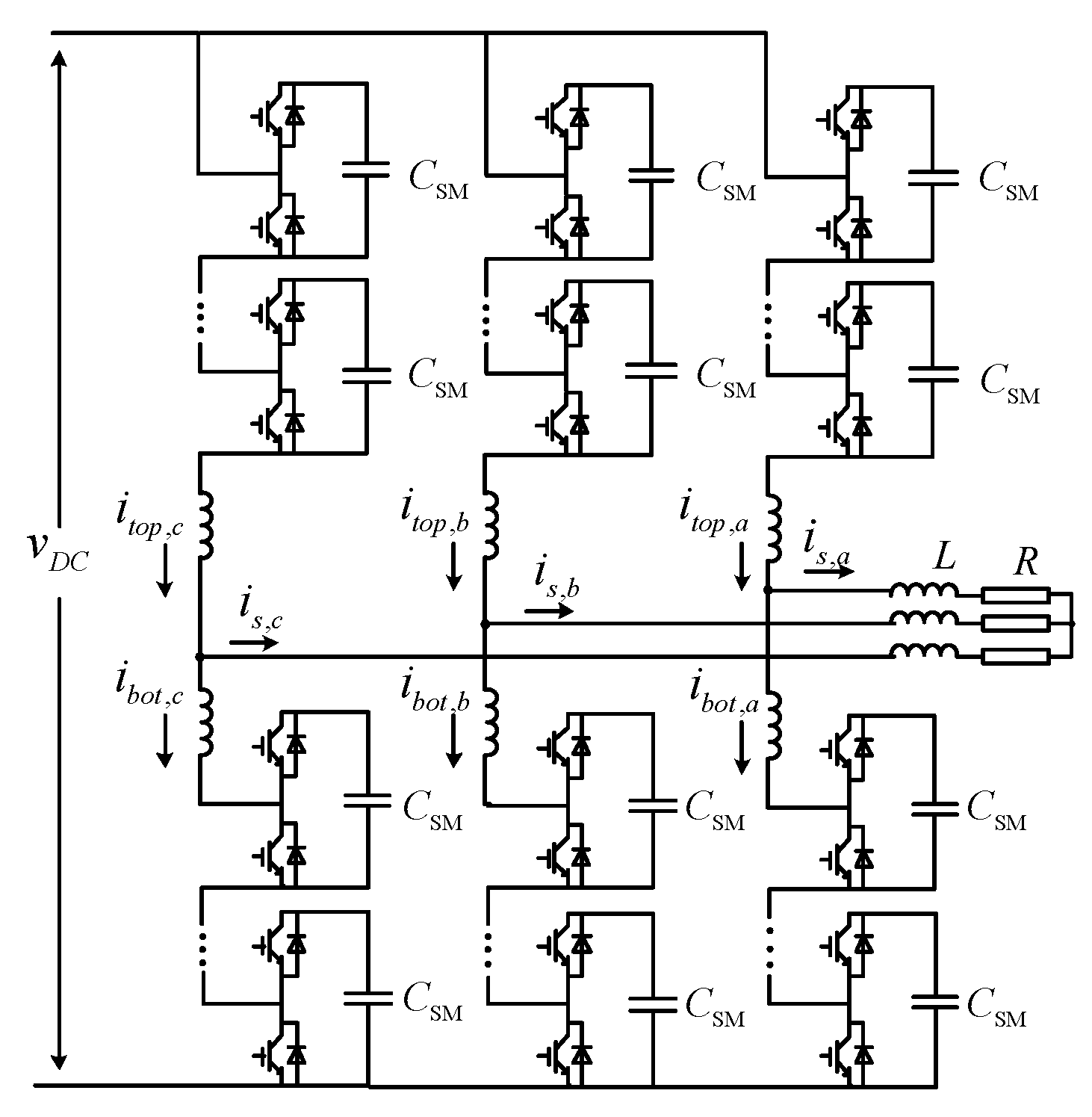
2.1. MMC Structure
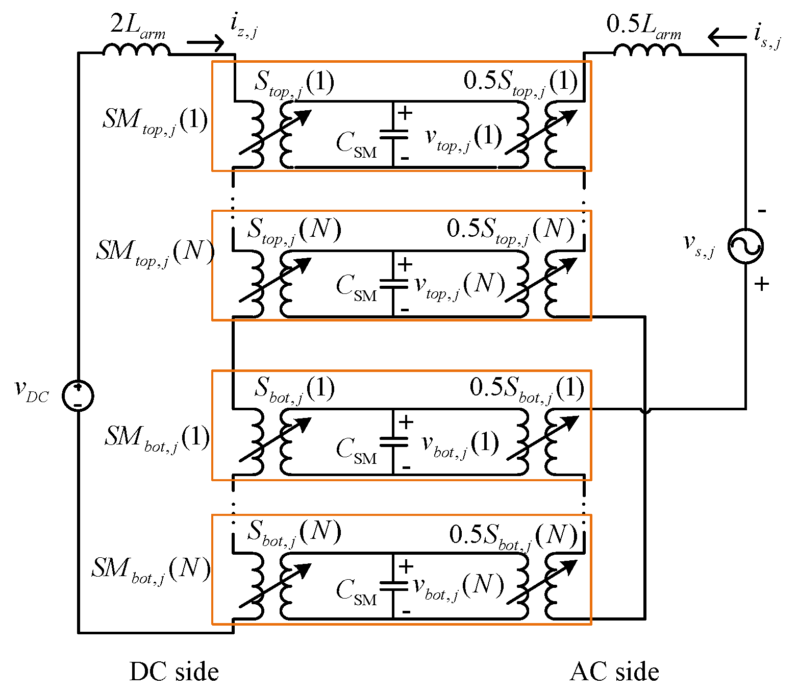
2.2. Model of MMC
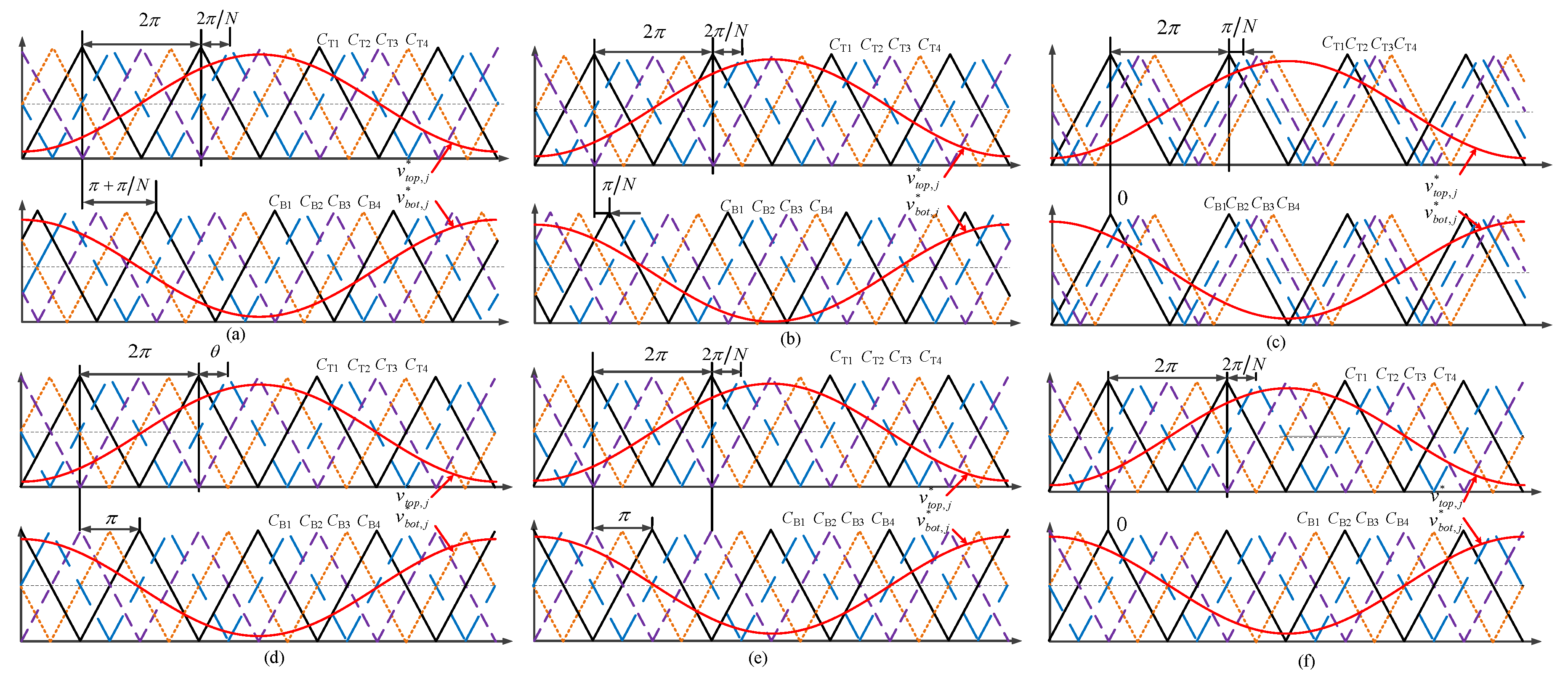
3. Phase-Shifted PWM Schemes for MMC
3.1. Fourier Series Representation of Switching Functions
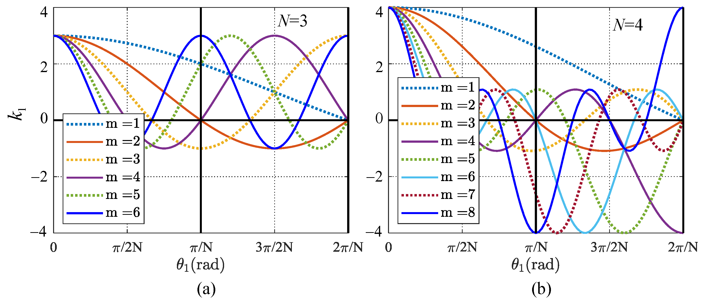
3.2. Harmonic-Cancellation Characteristics of MMC with PSC-SPWM
3.3. Capacitor Voltage of SMs Affected by PSC-SPWM Schemes
4. Simulation and Experiment Results
4.1. Simulation Results
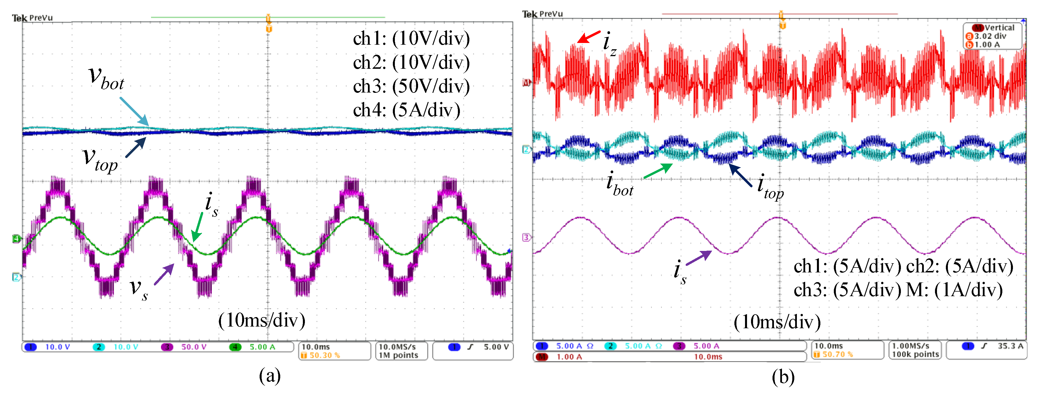
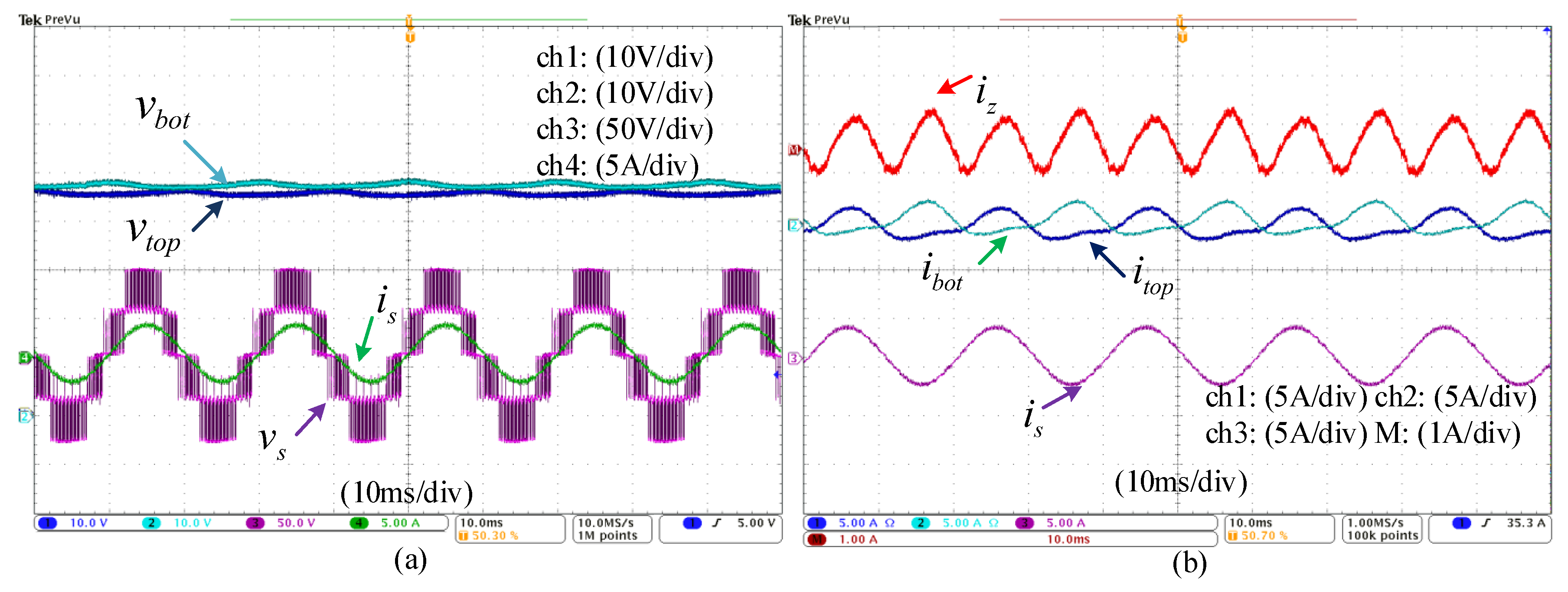
4.2. Experiment Results
5. Conclusions
Author Contributions
Funding
Acknowledgments
Conflicts of Interest
References
- Lesnicar, A.; Marquardt, R. An innovative modular multilevel converter suitable for a wide power range. In Proceedings of the 2003 IEEE Bologna Power Tech Conference Proceedings, Bologna, Italy, 23–26 June 2003; Volume 3, p. 6. [Google Scholar]
- Dekka, A.; Wu, B.; Fuentes, R.L.; Perez, M.; Zargari, N.R. Evolution of Topologies, Modeling, Control Schemes, and Applications of Modular Multilevel Converters. IEEE Trans. Emerg. Sel. Topics Power Electron. 2017, 5, 1631–1656. [Google Scholar] [CrossRef]
- Zhang, J.; Xu, S.; Din, Z.; Hu, X. Hybrid Multilevel Converters: Topologies, Evolutions and Verifications. Energies 2019, 12, 615. [Google Scholar] [CrossRef]
- Solas, E.; Abad, G.; Barrena, J.A.; Aurtenetxea, S.; Cárcar, A.; Zając, L. Modular Multilevel Converter With Different Submodule Concepts—Part II: Experimental Validation and Comparison for HVDC Application. IEEE Trans. Ind. Electron. 2013, 60, 4536–4545. [Google Scholar] [CrossRef]
- Yang, X.; Xue, Y.; Chen, B.; Lin, Z.; Mu, Y.; Zheng, T.Q.; Igarashi, S.; Li, Y. An enhanced reverse blocking MMC with DC fault handling capability for HVDC applications. Electr. Power Syst. Res. 2018, 163, 706–714. [Google Scholar] [CrossRef]
- Bina, M.T. A Transformerless Medium-Voltage STATCOM Topology Based on Extended Modular Multilevel Converters. IEEE Trans. Power Electron. 2011, 26, 1534–1545. [Google Scholar]
- Cupertino, A.F.; Farias, J.V.M.; Pereira, H.A.; Seleme, S.I.; Teodorescu, R. Comparison of DSCC and SDBC Modular Multilevel Converters for STATCOM Application During Negative Sequence Compensation. IEEE Trans. Ind. Electron. 2019, 66, 2302–2312. [Google Scholar] [CrossRef]
- Chen, Y.; Zhao, S.; Li, Z.; Wei, X.; Kang, Y. Modeling and Control of the Isolated DC–DC Modular Multilevel Converter for Electric Ship Medium Voltage Direct Current Power System. IEEE Trans. Emerg. Sel. Topics Power Electron. 2017, 5, 124–139. [Google Scholar] [CrossRef]
- Hagiwara, M.; Nishimura, K.; Akagi, H. A Medium-Voltage Motor Drive With a Modular Multilevel PWM Inverter. IEEE Trans. Power Electron. 2010, 25, 1786–1799. [Google Scholar] [CrossRef]
- Sau, S.; Fernandes, B.G. Modular Multilevel Converter Based Variable Speed Drive With Reduced Capacitor Ripple Voltage. IEEE Trans. Ind. Electron. 2019, 66, 3412–3421. [Google Scholar] [CrossRef]
- Ma, F.; Xu, Q.; He, Z.; Tu, C.; Shuai, Z.; Luo, A.; Li, Y. A Railway Traction Power Conditioner Using Modular Multilevel Converter and Its Control Strategy for High-Speed Railway System. IEEE Trans. Transp. Electrif. 2016, 2, 96–109. [Google Scholar] [CrossRef]
- Wang, Z.; Zheng, Z.; Li, Y.; Li, G. Modulation and Control Strategy for Electric Traction Drive System of Rail Transit Vehicles. Trans. China Electrotech. Soc. 2016, 31, 223–232. [Google Scholar]
- Konstantinou, G.; Pou, J.; Ceballos, S.; Darus, R.; Agelidis, V.G. Switching Frequency Analysis of Staircase-Modulated Modular Multilevel Converters and Equivalent PWM Techniques. IEEE Trans. Power Del. 2016, 31, 28–36. [Google Scholar] [CrossRef]
- Samajdar, D.; Bhattacharya, T.; Dey, S. A Reduced Switching Frequency Sorting Algorithm for Modular Multilevel Converter With Circulating Current Suppression Feature. IEEE Trans. Power Electron. 2019, 34, 10480–10491. [Google Scholar] [CrossRef]
- Tu, Q.; Xu, Z.; Xu, L. Reduced Switching-Frequency Modulation and Circulating Current Suppression for Modular Multilevel Converters. IEEE Trans. Power Del. 2011, 26, 2009–2017. [Google Scholar]
- Pérez-Basante, A.; Ceballos, S.; Konstantinou, G.; Pou, J.; Andreu, J.; de Alegría, I.M. (2N+1) Selective Harmonic Elimination-PWM for Modular Multilevel Converters: A Generalized Formulation and A Circulating Current Control Method. IEEE Trans. Power Electron. 2018, 33, 802–818. [Google Scholar] [CrossRef]
- Dekka, A.; Wu, B.; Zargari, N.R.; Fuentes, R.L. A Space-Vector PWM-Based Voltage-Balancing Approach With Reduced Current Sensors for Modular Multilevel Converter. IEEE Trans. Ind. Electron. 2016, 63, 2734–2745. [Google Scholar] [CrossRef]
- Ronanki, D.; Williamson, S.S. A Simplified Space Vector Pulse Width Modulation Implementation in Modular Multilevel Converters for Electric Ship Propulsion Systems. IEEE Trans. Transp. Electrif. 2019, 5, 335–342. [Google Scholar] [CrossRef]
- Ilves, K.; Harnefors, L.; Norrga, S.; Nee, H. Analysis and Operation of Modular Multilevel Converters with Phase-Shifted Carrier PWM. IEEE Trans. Power Electron. 2015, 30, 268–283. [Google Scholar] [CrossRef]
- Zhou, D.; Yang, S.; Tang, Y. Model-Predictive Current Control of Modular Multilevel Converters With Phase-Shifted Pulsewidth Modulation. IEEE Trans. Ind. Electron. 2019, 66, 4368–4378. [Google Scholar] [CrossRef]
- Sasongko, F.; Sekiguchi, K.; Oguma, K.; Hagiwara, M.; Akagi, H. Theory and Experiment on an Optimal Carrier Frequency of a Modular Multilevel Cascade Converter With Phase-Shifted PWM. IEEE Trans. Power Electron. 2016, 31, 3456–3471. [Google Scholar] [CrossRef]
- Li, B.; Yang, R.; Xu, D.; Wang, G.; Wang, W.; Xu, D. Analysis of the Phase-Shifted Carrier Modulation for Modular Multilevel Converters. IEEE Trans. Power Electron. 2015, 30, 297–310. [Google Scholar] [CrossRef]
- Cheng, Q.; Wang, C. Comparison of Phase-Shifted Carrier PWM Schemes for Modular Multilevel Converter. In Proceedings of the 2019 IEEE Energy Conversion Congress and Exposition (ECCE), Baltimore, MD, USA, 29 September–3 October 2019; pp. 4801–4807. [Google Scholar]
- Van der Merwe, W. Natural Balancing of the 2-Cell Modular Multilevel Converter. IEEE Trans. Ind Appl. 2014, 50, 4028–4035. [Google Scholar] [CrossRef]
- Lipo, T.; Holmes, D. Pulse Width Modulation for Power Converters: Principles and Practice; Wiley: Hoboken, NJ, USA, 2003. [Google Scholar]


| Quantity | Symbol | Values |
|---|---|---|
| DC bus voltage | 200 V | |
| Submodule capacitance | 3.6 mF | |
| Number of submodules | N | 4 |
| Bridge inductance | 2 mH | |
| Carrier frequency | 1000 Hz | |
| Load inductance | L | 5 mH |
| Load resistance | R | 24 |
| Modulation index | M | 0.8 |
| PSC1 | PSC2 | PSC3 | PSC4 | PSC5 | |
|---|---|---|---|---|---|
| Output level | |||||
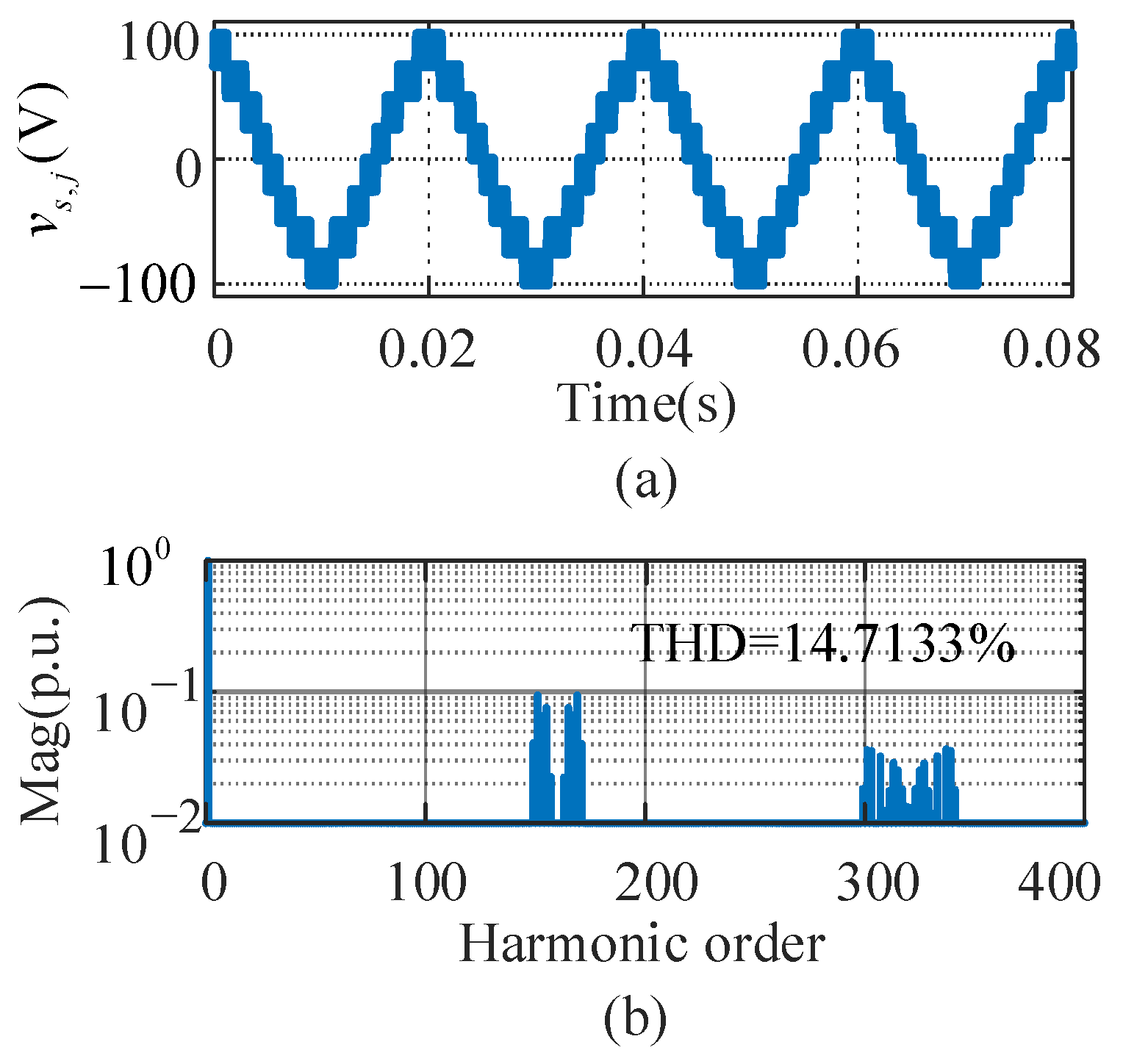
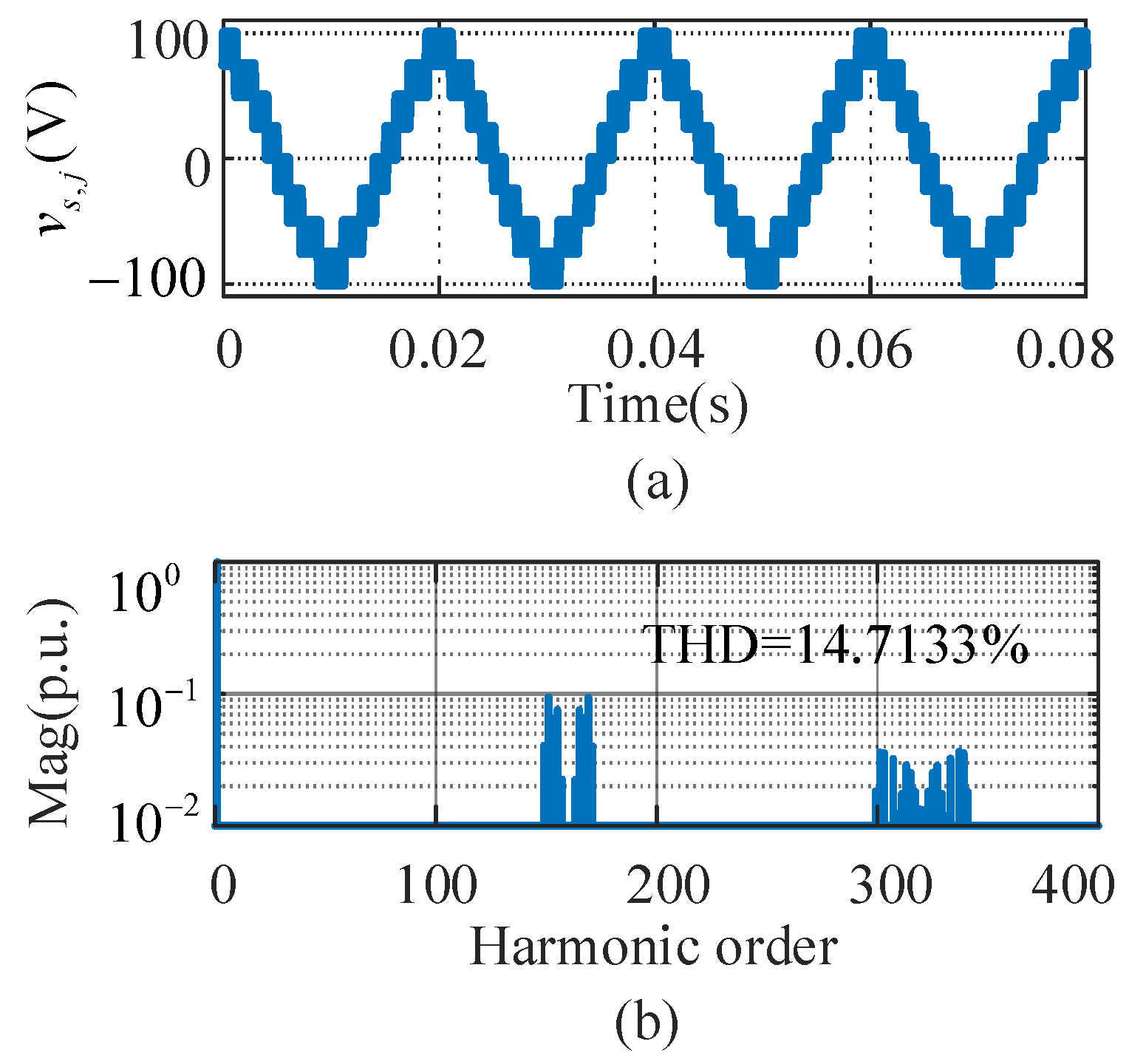
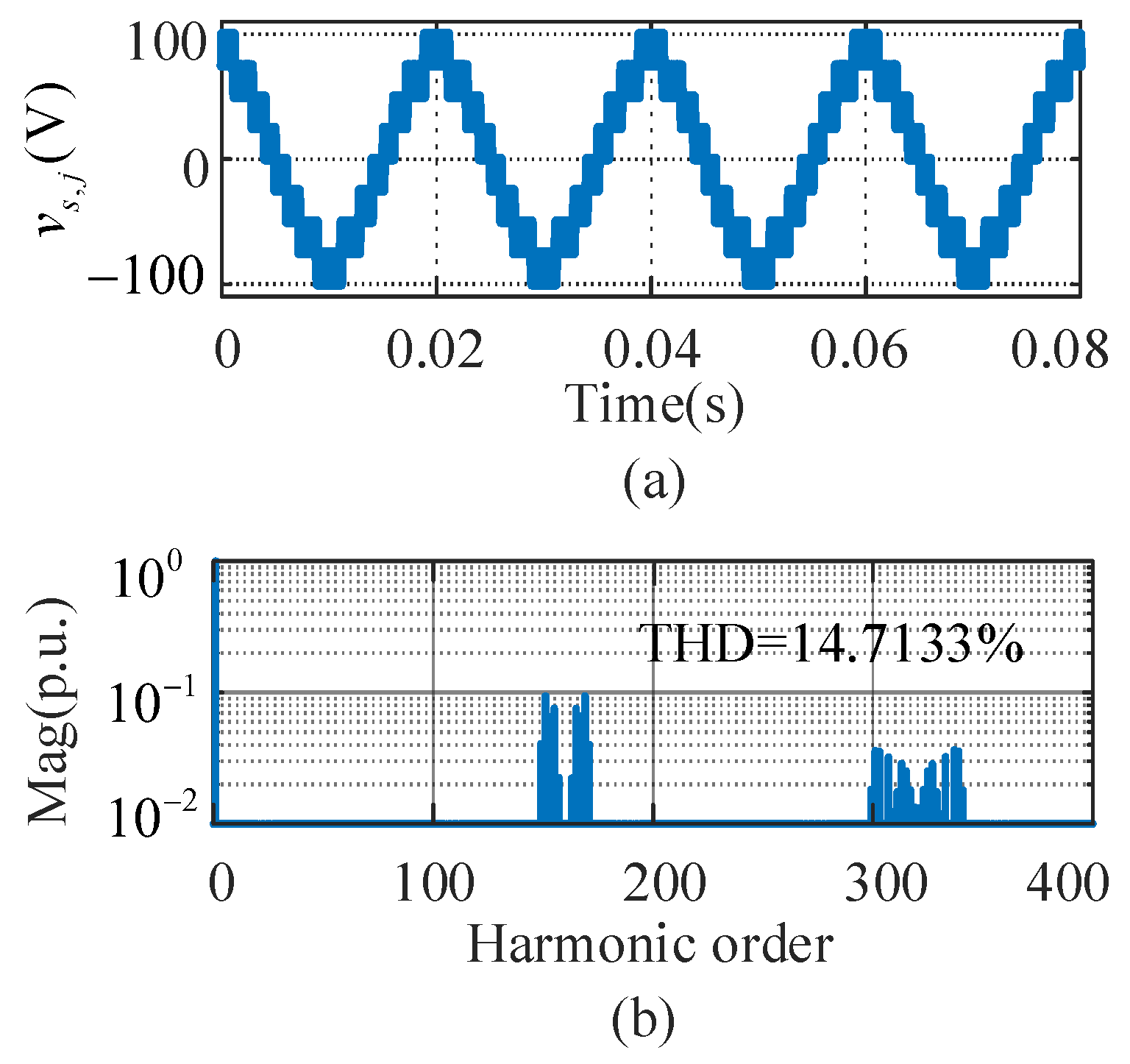
| Output-voltage harmonics | |||||
| Circulating-current harmonics | 0 | 0 | |||
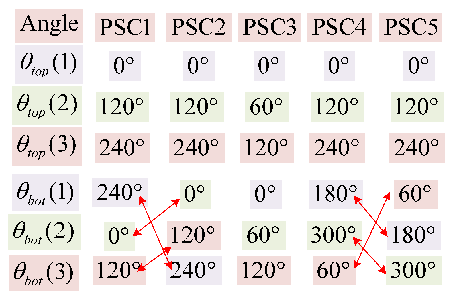
| Expression of displacement angles | fixed | Different with parity of N | fixed | fixed | Different with parity of N |
| Voltage stability of capacitors | stable | stable | unstable | stable | stable |
Publisher’s Note: MDPI stays neutral with regard to jurisdictional claims in published maps and institutional affiliations. |
© 2020 by the authors. Licensee MDPI, Basel, Switzerland. This article is an open access article distributed under the terms and conditions of the Creative Commons Attribution (CC BY) license (http://creativecommons.org/licenses/by/4.0/).
Share and Cite
Cheng, Q.; Wang, C.; Wang, J. Analysis on Displacement Angle of Phase-Shifted Carrier PWM for Modular Multilevel Converter. Energies 2020, 13, 6743. https://doi.org/10.3390/en13246743
Cheng Q, Wang C, Wang J. Analysis on Displacement Angle of Phase-Shifted Carrier PWM for Modular Multilevel Converter. Energies. 2020; 13(24):6743. https://doi.org/10.3390/en13246743
Chicago/Turabian StyleCheng, Qian, Chenchen Wang, and Jian Wang. 2020. "Analysis on Displacement Angle of Phase-Shifted Carrier PWM for Modular Multilevel Converter" Energies 13, no. 24: 6743. https://doi.org/10.3390/en13246743
APA StyleCheng, Q., Wang, C., & Wang, J. (2020). Analysis on Displacement Angle of Phase-Shifted Carrier PWM for Modular Multilevel Converter. Energies, 13(24), 6743. https://doi.org/10.3390/en13246743