Abstract
In recent years, multi-phase permanent magnet synchronous generators (PMSGs) have become attractive in the field of tidal current energy conversion systems (TCECS) due to their high-power density, reliability, and availability. However, external disturbances and malfunctions in power conversion chains will bring challenges to achieving stable and continuous tidal current energy harnessing. Using generalized proportional integral observers, an active fault-tolerant control (AFTC) strategy is therefore proposed for a five-phase PMSG based TCECS that is subjected to an open switch fault (OSF) in the generator side converter. This proposed AFTC strategy is applied into q-axis current control loops, which contain fault detection and compensation. The fault compensator will be smoothly activated using a sigmoid function once the OSF is detected. Finally, a small-scale power experimental platform emulating the TCECS is established in order to verify the feasibility and efficiency of the proposed FTC strategy. Experiment results show that this AFTC strategy can detect faults rapidly and effectively attenuate torque ripples in the post-fault operation mode.
1. Introduction
Tidal current energy has predominant advantages relative to other types of renewable energies, such as predictability, high power density, and energy continuity at almost all times, which significantly facilitates controller designs and grid connection [1]. Nevertheless, the power generation equipment, the so called tidal current turbine, is always vulnerable to harsh marine conditions that pose daunting challenges for maintenance [2]. As a result, the exploration of advanced solutions with high fault tolerance has become a main objective to practitioners and theoreticians.
For this concern, breakthroughs can be made utilizing multi-phase machines, which meet the requirements of fault tolerance since they provide redundant structures than the classical three-phase machinery [3]. Thus, the multi-phase machine nowadays is widely applied into the fields of offshore marine energies, warships, aerospace and so on [4]. A great number of works have been undertaken in the past few decades concerning the FTC approaches related to multiphase machines. All of these contributions can be generally categorized [5] into passive FTC (PFTC) and active FTC (AFTC) methods. PFTC is usually realized based on robust controlling theories [6] that will force the controller with low sensitivities to fault components. For instance, Mekri et al. [7] provide a comparative study between three and five-phase permanent magnet synchronous generator (PMSG) in a tidal current energy conversion system (TCECS) by imposing an optimal torque reference and second-order sliding mode torque/current controllers. Pham et al. [8] proposed a fault tolerant strategy incorporating finite control set and model predictive control methods for a five-phase PMSG based TCECS. Single-phase and double-phase open circuits are focused on in this work with the concern of constant and variable marine tidal current velocities. A fault-tolerant controller design is proposed by Baudart et al. [9] through Lagrangian formulation based optimal torque references as well as reconfiguration of current controllers. A limitation torque control strategy according to the response of torque commands was designed by Guo et al. [10] considering both short circuit and open circuit faults in a dual stator based ten-phase machine. These PFTC methodologies are able to achieve great robustness and implementability in normal and abnormal operation modes while they have obvious shortcomings, such as complicated design process of controllers, lack of supports of fault information. Consequently, research of AFTC has become a promising direction in recent years. Conventionally, an AFTC mechanism lies in utilization of results from fault detection and diagnosis, offering evidences for further actions in post-fault operation modes. Fault status, size, and locations can be recognized by using fault estimation techniques, which plays an essential role in building AFTC theories [11,12]. Many efforts [11,13,14,15,16] have been made on the basis of this consensus. Among all of these research achievements, fault estimation and compensation based on disturbance observer (DOB) has attracted a lot of attentions benefit from more degrees of control freedom, high implementability in real-time, etc. A generalized DOB family defined by Chen et al. [17] contains linear and nonlinear DOB, equivalent input disturbance, extended state observer (ESO), generalized proportional integral observer (GPIO) [18,19], extended high-gain state observer and so forth. Almost all of these DOB methods can provide information of multi-state estimation, which plays an important role in disturbance attenuation. Selecting an appropriate DOB method is a main concern in practice, which depends on the complexity of parameter setting and realizability of online deployment.
In order to increase the reliability and availability of the tidal application in real time, an AFTC strategy is proposed by GPIO and applied to a five-phase PMSG based TCECS. Under the framework of GPIO, this proposed method contains an adaptive threshold-based fault detection method using form factors (FFs) [20] and fault compensation-based FTC are developed. Specially, a smooth activation-based fault compensation mechanism is incorporated to improve the transient behaviors due to the sudden action of compensation. Finally, a small-scale power full-physical experimental platform is carefully established to validate the effectiveness and efficiency of the proposed AFTC strategy.
The remainder of this paper is organized as follows. Section 2 introduces system modelling and basic descriptions of the whole TCECS, which concentrates on the generator side. Section 3 gives detailed design procedures of the proposed AFTC strategy. In Section 4, the effectiveness and performance of the proposed strategy will be experimentally verified under an OSF case. In the end, Section 5 concludes this paper.
2. System Description and Modelling
The studied system shown in Figure 1 presents the generator side of a tidal current energy conversion system. It is composed by a five-phase PMSG which is connected to a DC load through a five-leg converter. Figure 1 also indicates a most fundamental type of fault in the TCECS investigated in this paper, namely the OSF of the power switch. The OSF condition is achieved by blocking the switching part excluding the anti-parallel diode.
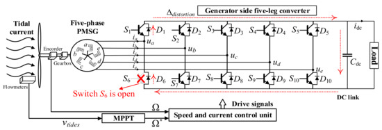
Figure 1.
A five-phase PMSG based tidal current energy conversion system in generator side.
2.1. Resource of Tidal Current
The acquired hydrodynamic energy [21] from the tidal current can be calculated by
where ρ represents the density of sea water, νtides means the tidal current velocity, and R indicates the radius of turbine blade. Cp is the power coefficient, depending on tip speed ratio (TSR, λ = ΩR/νtides) and pitch angle β, whose expression is given by Equation (2).
where C1–C6 are the coefficients of Cp(λ, β).
2.2. Tidal Current Turbine
A Cp curve is given as shown in Figure 2a. The mechanical speed is denoted as Ω. P-Ω characteristics of the turbine are depicted in Figure 2b under various tidal current velocities. Working process of a tidal current turbine can be divided into 3 parts: starting, maximum power point tracking (MPPT), and constant power operational stages. This paper focuses on the second one where the pitch angle control is not carried out yet (β = 0). In this paper, cut-in speed and rated speed are 1 m/s and 3.2 m/s, respectively.
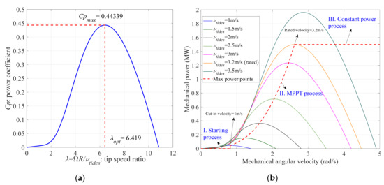
Figure 2.
Characteristics of tidal current turbine: (a) Cp curve, (b) P-Ω curves under various velocities.
2.3. Dynamic Model of Five-Phase PMSG
To facilitate the dynamic modelling, here magnetic saturation, core losses and temperature variations are neglected. Figure 3 describes an equivalent structure of star connected windings. M1 and M2 represent mutual inductances among the adjacent (2π/5 phase shift) and non-adjacent (4π/5 phase shift) phase windings, respectively.
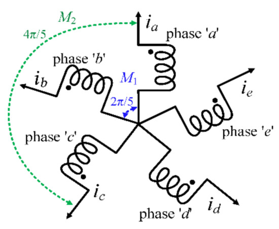
Figure 3.
Five phase star connected windings.
The electrical voltage equation of five-phase PMSG can be written as below in original abcde frames.
subject to
where U, E, R, I, and L represent the output, back-electromagnetic forces (back-EMFs), phase resistances, phase current and generator inductances, respectively. The self-inductance of phase windings is defined as Ls. The expression of back-EMFs in original abcde frames are given by
where the positive odd number h represents the harmonic orders. θ and p represent the electrical angle and the number of pole pairs of the generator, respectively. Φh represents the magnet flux corresponding to the hth order harmonic component of the back-EMFs.
As a result, the experimental waveforms of the trapezoidal back-EMFs for the small-scale power five-phase PMSG can be seen in Figure 4a. In Figure 4b, the harmonic orders become clear to see that the back-EMFs mainly contain 1st, 3rd, 5th, 7th, and 9th harmonic components.
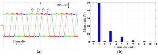
Figure 4.
Back-EMFs of the used five-phase PMSG at 50Hz: (a) Waveforms, (b) Harmonic orders.
A five-phase PMSG can be decomposed into three 3-phase sub-machines [22,23] (primary, secondary and homopolar sub-machines). Table 1 presents a harmonic distribution rule with respect to the three sub-machines.

Table 1.
Distribution rule of back-EMF harmonic components in a five-phase PMSG.
Without connecting the neutral point, the homopolar sub-machine is negligible in this paper. By using a transformation matrix TPark given in Equation (6), Equation (3) will be thereby projected into stationary coordinate frames (Park frames) as
where
With respect to Equation (4), the expressions of back-EMFs in Park frames are thereby deduced as
It should be noted that only 1st and 3rd harmonic components in the back-EMFs will be taken into account for controller designs by neglecting 7th and 9th ones. That is to say, the 10 times terms in Equation (7) will be unconsidered in this paper.
Electrical torque can be thus written as below by using vectors in Park frames.
Additionally, the five-phase PMSG is essentially an inertial motion system that can be indicated by a first order mechanical equation as below.
where Γ and Γem represent the mechanical and electromagnetic torques. Moment of inertia and friction coefficient are denoted as J and f, respectively.
3. Proposed AFTC Strategy
3.1. Principle of GPIO-Based AFTC Strategy in a Classical Close-Loop System
A scalar second order SISO system with a concern of systematic lumped disturbance can be expressed as
where x1 represents the system state. x2 is a augmented state used to estimate the lumped disturbance dl. The system input gain, output gain and measurement gain are denoted as a1, b1 and c1, respectively. Here, c1 is equal to 1 and b1 ≠ 0.
In fact, the lumped disturbance dl represents a bounded perturbated term, which may contain linear or nonlinear perturbations from model uncertainties and external noises. In detail, the model uncertainties originated from modeling mismatches, which are mainly caused by parameter variations and fault occurrences. The lump disturbance term can be expressed as below by a combination of model uncertainties or external interferences.
where Δpara represents a time varying output term due to the parameter variation. Δf represents the fault component, which highly relies on the type of fault, which will determine its size, harmonic content, and degree of nonlinearity. It should be noted that the measurement noises Δnoise can be neglected by using some engineering techniques, such as filters. The parameters a1 and b1 will vary from the nominal value during operations, which can be expressed as
According to Equations (10) and (12), the term Δpara can be deduced as
Compared with the most used ESO, GPIO is chosen in this paper to design the compensator since it is easy to implement and will provide more state information to increase the estimation accuracy. According to Equations (10)–(13), a full order expression of GPIO can be given by
where n is a positive integer that represents the order of states. α1 to αn are the observer gains. Importantly, ESO can be obtained without using any auxiliary states.
In terms of a feedback close loop, the PI controller can be formulated as Kp + Ki/s, where s represents the operator in s-plane. Hence, the compensated output can be written as below. Hereafter the superscript “*” represents the corresponding reference value.
where Kcomp means an adjustable gain of compensation, which related to the working conditions, such as healthy and faulty operation modes. In nominal condition, Kcomp = 1. The activation function fcnact should maintain the system operating smoothly concerning avoidance of high transient overshoots with the sudden injection. The diagram of this AFTC strategy for the system Equation (10) can be organized in Figure 5. The fault detection will be realized by comparing the residual and the threshold. Fault compensation will be activated immediately once fault is detected via the activation function.
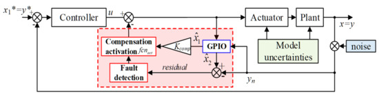
Figure 5.
Diagram of GPIO-based AFTC strategy for a 2nd-order SISO close-loop system.
3.2. GPIO-Based AFTC Strategy Design Example for a Five-Phase PMSG Power Convertion System
Relying on the description in the previous subsection, a five-phase PMSG based TECES example is taking into account here. Figure 6 indicates the whole control strategy of the five-phase PMSG based TECES using the field-oriented control (FOC) theory and the GPIO-based AFTC sstrategy. Since current in q-axis is directly related to the electromagnetic torque, this AFTC strategy is carried out in the q-axis of the inner current loops. Firstly, the fault detection part is realized only based on the estimated residual of q-axis current corresponding the primary sub-machine. Once fault is detected, the compensation will be activated promptly into the q-axis control loops relative to the two sub-machines.
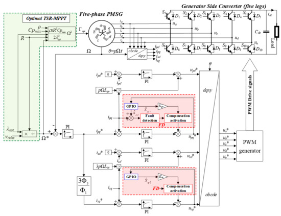
Figure 6.
Active fault-tolerant control scheme of a five-phase PMSG based TCECS.
3.2.1. Basic Control Strategy in Dual Loops
First of all, PI-based controllers in dual loops plus an optimal TSR-MPPT algorithm will be presented as follows in order to provide a foundation for the proposed GPIO-based AFTC strategy in speed loop.
- Optimal control references
In this paper, an optimal TSR-based MPPT algorithm [24] is introduced to offer an expected speed reference. This algorithm can guarantee the whole system to capture needed maximum powers under each νtides by exploiting the optimal TSR λopt and the max power coefficient Cpmax. Thus, expected speed reference and optimal mechanical torque are expressed as
To minimize copper losses [25,26], the current vectors and the back-EMF vectors will satisfy Fleming’s right-hand rule, which can be expressed as below (epd = esd = 0).
where Xr represents a magnetic ratio between the two sub-machines.
According to the FOC theory, the expected torque can be calculated by
Substituting Equations (17) and (18), the current references are given by
where Kt represents a conversion gain between reference electromagnetic torque and reference of q axis current in the primary sub-machine.
- PI-based controller design in dual loops
Here, the generator side converter can be modeled by a nonlinear delay as Kpwm/(1 + 1.5Tpwms) due to sampling and switching time, where Tpwm (is equal to 1/fpwm) is the time constant of switching frequency. Kpwm, the equivalent gain of the PWM modulator, can be expressed as Kpwm = Vdc/Vcarrier in the linear range, Vcarrier is the amplitude of carrier signals, which is usually set as 1. Thus, PI parameters in current loop controllers can be calculated by
Moreover, for the outer speed loop controller, the PI parameters are given by
where TΩ = (τΩ + 3Tpwm). τΩ is denoted as the sampling delay of the speed. In this paper, τΩ = 5Tpwm.
3.2.2. Observer Design
State form currents in q-axis for primary and secondary sub-machines can be rewritten as below according to Equations (5) and (6), and Equations (10) and (11). It should be noted that here the coupling terms are also incorporated in the lumped disturbances for sake of compensation.
where dl_pq and dl_sq are the lumped disturbance in the q-axis for primary and secondary sub-machines, respectively.
- Analysis of lumped disturbance terms
Similar to Equations (11)–(13), these two lumped disturbance terms can be generally extracted as
The noise terms will not be discussed by the analysis in Equation (11). There exist variations of machine parameters relative to their nominal values in different working conditions, which can be expressed as
Accordingly, the time varying output terms (Δpara_pq, Δpara_sq) in q-axis for the five-phase PMSG can be expressed as
In a leg of the generator side converter, the phase current in one period under an OSF situation (e.g., the OSF occurs at a lower switch) can be expressed as
where k = 1, 2, 3, 4, 5 represents the kth phase from phase ‘a’ to phase ‘e’. h is the number of harmonic orders in back-EMF of the five-phase PMSG. Ih represents the magnitude of hth harmonic component of the phase current.
For a generator side converter, the half cycle under the single OSF condition exists some distortions instead of complete null blocking values due to the conduction of unremoved diodes. For instance, the unexpected current will form a close loop passing D1, load and D6 as shown in Figure 1. The distorted signal will not be blocked during the cycle where the faulty switch S6 should have been triggered. This term of conducted distortions is denoted as Δdistortion, which is determined by the system power scale, control, and load parameters, etc. After fast Fourier transform (FFT) of the faulty signal in Equation (26), the additional harmonics are mainly constituted by DC component and other even-order frequencies relative to the spectrum in healthy condition. In stationary coordinate frames, the fault signal fpd and fpq will mainly contain the harmonics except for the DC component. This issue will be discussed latter.
- Construction of GPIO
Constituting Equations (22) and (23), we have
Define the states ipq and isq as xpq1 and xsq1, dl_pq and dl_sq as xpq2 and xsq2, respectively. Augmented state space form can be expressed as
In order to estimate the current states xpq1, xsq1 as well as the lumped disturbance states xpq2, xsq2, generalized proportional integral observers in the speed loop will be designed as
where αpq1–αpqn, αsq1–αsqn represent observer gains, and they are positive real numbers.
3.2.3. Procedures of the Proposed AFTC Strategy
On the basis of the designed GPIO in Section 3.2.1, steps of this proposed AFTC strategy can be summarized as:
- Fault detection
The form factors (FFs) [20] of ipq and its measurement are given by
The RMS value reflects the variation of distance for phase currents from their corresponding average values, and is sensitive by deviations from the unrectified average values, such as the OSF. Thus, here FFs are utilized for fault detections. The notation “ave” represents average operations within one fundamental period.
A residual between the two form factors is yielded by
where epq is the observer error given by
Thus, the residual in (31) is subject to the following relationship:
Finally, the adaptive threshold for fault detection can be expressed by
where thf determines the value of fault status FD that it will be 0 or 1 only in healthy and faulty conditions, respectively.
- Fault compensation
The dynamic performance of the compensation is closely related to the way of activation in a close-loop control system. This paper utilizes a smooth activation mechanism based on a sigmoid function. This sigmoid function is actually a nonlinear activation function, whose advantages have been validated and already used widely in the field of neural networks [27].
The sigmoid function is indicated by the red curve in Figure 7 where γ, t0, t1 represent the coefficient of bandwidth, starting time of compensation and ending time of compensation, respectively. As mentioned earlier, the compensation in q-axis current control loops will be activated once a fault is detected. In fact, the dynamic behaviors of compensation can be tuned by modifying γ, t1. Instantaneous compensation will be triggered at t0 once fault status FD = 1. The output of the activation function will be equal to zeros if FD = 0. Compared with a classical step activation function (blue dotted curve), a sigmoid function will bring satisfied transient behaviors for the whole system which smooths the sudden action of compensation.
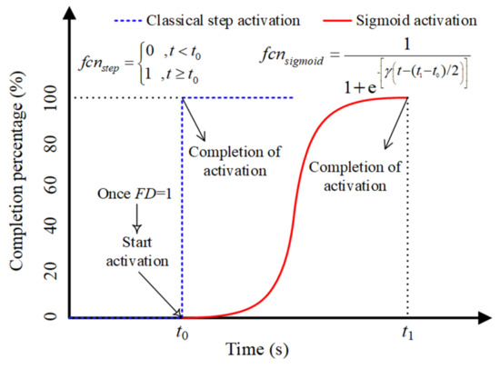
Figure 7.
Illustrations of activation functions for compensation.
By (15) and (27)–(29), the composite controllers with compensation can be reconfigured as
where Kpr and Kse are respectively the adjustable compensation gains for upq and usq. Their theoretical values are equal to 1 in a nominal condition.
The above step by step design procedures of the proposed AFTC strategy are synthesized in Figure 8. The error between ipq and is firstly converted into form factors. If the fault status FD equal to 1, the fault information will be injected in the upq and usq, respectively.
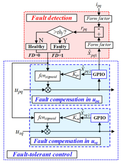
Figure 8.
Block diagram of AFTC strategy in q-axis of a five-phase PMSG system.
4. Experimental Verification
A small-scale power experimental platform by full-physical devices is built so as to validate the proposed AFTC strategy.
4.1. Description of Small-Scale Power Experimental Platform
As shown in Figure 9, this full-physic experimental platform is able to convert power from a five-phase PMSG to the DC-link. Here, a 3.3 kW five-phase PMSG is adopted that is driven by a DC motor. Original position information of the generator is acquired by a 12-bit absolute encoder. The five-leg converter incorporates two three-leg converters. DC supplies ranging from 10–30 V are adopted to offer constant voltage to conditioning circuit, dSPACE (Paderborn, Germany) plant (MicroAutobox II), I/O connector, the drive boards of the converter and the pulse width modulation (PWM) activation card. A personal computer (PC) installed MATLAB/SIMULINK and ControlDesk softwares will be used for program execution, real-time parameters turning and system monitoring. A multi-channel oscilloscope (Yokogawa DL-750) is utilized to acquire experimental results. With the assistance of dSPACE, the conditioning circuit can well adapt the input and output analog signals. Speed and electrical angle calculation unit provides precise θ and Ω in real-time operations relying on the high-efficient encoder. The main parameters of this platform are summarized in Table A1 of Appendix A.
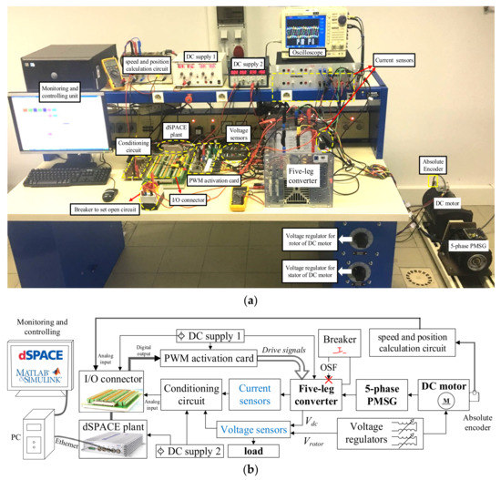
Figure 9.
Small-scale tidal current power generation experimental platform: (a) Real illustration of full-physical platform, (b) Diagram of system connection.
Particularly, two voltage regulators are quite essential, which control the speed of DC motor in order to emulate the tidal current velocity. During the experimental process, variable speed reference can be obtained by manual or programmable adjustment of voltage regulator for the rotor. The speed controller is thus accessible when the voltage for the stator and the load are constant. Under careful investigations, mechanical speed Ω and voltage of the DC motor’s rotor Vrotor roughly subjects to a linear curve as Ω = 12 × (Vrotor − 4.7) when load = 242 Ohm, Vstator = 100 V.
Furthermore, hereafter validations of the proposed AFTC strategy will be carried out under a constant velocity profile considering a short period over time, such as one hour. Consequently, the gear ratio can be set as 1:40 to emulate the actual tidal profiles described in Figure 2.
4.2. Performance in Healthy and Faulty Conditions
Different with majority of research works about the disturbance attenuation under healthy conditions, post-fault tolerant control performance will be the main interest in this paper.
Number of states n in the GPIO formulated in Equation (29) is fixed as 3 taking into account of the complexity of parameter setting as well as performance of the AFTC strategy. To tradeoff the estimation errors and robustness of those estimates through the GPIO, parameters of the designed fault-tolerant composite controllers will be a key factor, which are organized in Table A2.
Torque’s ripple will be concerned since it can directly reflect the operational situation of the machine. Thus, torque’s ripple is the main regards to evaluate post-fault operation performances in this paper. There are no torque sensors involved in the platform, this electromagnetic torque can be thus derived from the calculation by current vectors in Park frames as Equation (8). A calculation method of the torque ripples is given by.
4.2.1. Disturbance Suppression in Healthy Conditions
As shown in Figure 10, the compensation part is put into use in healthy conditions. Obvious to see, the compensation using the proposed strategy will significantly suppress the torque ripples and disturbances in phase current. The compensators in the proposed method will contribute about 10% reduction of the torque ripples from 4.82% to 3.04%. In order to specify the oscillations of torque, its waveform is recorded by means of “AC”. The actual information of the signals by the oscilloscope can be found in the footnotes of the Figure 10a. As the depicted harmonic orders in Figure 10b, the additional first harmonic in the torque signal is effectively suppressed and the rest of harmonic order from 2nd to 9th can be almost also reduced using the compensators in healthy conditions. Therefore, the compensation mechanism described in Equation (35) is also feasible in healthy conditions.
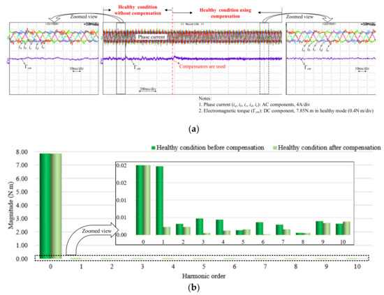
Figure 10.
Experimental test of disturbance suppression by proposed strategy in healthy conditions: (a) Waveforms recorded by oscilloscope, (b) Spectrum analysis.
According to Equations (11) and (23), the lumped disturbance mainly contains the issue by model uncertainties and noises. In this practical machinery system, the model uncertainties mainly attribute to the unmodeled terms, such as parameter variation effects, cogging torque, and non-linearity of magnetizing curve, etc. The test results thereby demonstrate that the compensation strategy can also be adapted to the issue of disturbance suppression in healthy conditions.
4.2.2. Performance of Active Fault-Tolerant Control in Faulty Conditions
- Performance under an OSF case without using AFTC
In accordance with the expressions from (26, there exist current distortions during the blocking cycles of switch S6 as shown in the right most subfigure in Figure 11. Based on Equation (36), this five-phase PMSG has 4.81% and 28.48% torque ripples in the healthy and faulty conditions. Once the OSF occurs, speed also has periodical perturbations in a small range around 600 rpm. Whereas torque has more significant oscillation with around 1.45 N·m. Similarly, the mechanical speed and its references are recorded by using the channel “AC” to observe the oscillating effect due to the OSF occurrence.
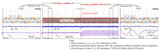
Figure 11.
Experimental test with OSF occurrence of S6 without the proposed AFTC strategy.
- Performance under an OSF case using AFTC
In the condition that switch S6 is open, using form factors will maintain the robustness and efficiency of fault detection, which will be completed within 5.6 ms (around 1/6 of fundamental period) as shown in the leftmost illustration of Figure 12. In the rightmost illustration of Figure 12, there will be only 0.64 N·m oscillated range of the torque in the post-fault operation process utilizing the proposed AFTC strategy. Thanks to the compensation mechanism, almost 60% of torque ripples can be suppressed. The speed fluctuations can be neglected relative to the improvements of torque ripples.
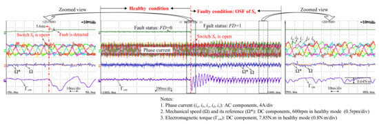
Figure 12.
Experimental test with OSF occurrence of S6 using the proposed AFTC strategy.
In terms of the results from Figure 11, it can be demonstrated that this proposed AFTC strategy owns high efficiency and feasibility in real-time operations with OSF occurrence, which is able to actively reduce the torque ripples. Thanks to the sigmoid activation function, the settling time and overshoots of either the electromagnetic torque or phase current are maintained satisfied dynamic transient behaviors. It can also be observed from the middle subfigure that the completion of compensating duration costs around 0.4 s. To obtain satisfied transient behaviors and robustness in faulty conditions, the parameters of the designed fault-tolerant composite controllers will be a key factor, as organized in Table A2.
- Spectrum analysis of torque
In order to explore the effects of the compensation in different conditions, the spectrum of the signal Γem is analyzed in the healthy condition, OSF condition of switch S6 and fault-tolerant condition, which are shown as Figure 13. It is clear to see that torque in the healthy condition mainly contains a constant DC component. Once switch S6 is open, the DC component is decreased by 0.05 N·m. The 1st harmonic becomes a most dominant additional component, which will impose a fluctuation operating at a fundamental frequency to the torque as shown in the rightmost illustration of Figure 11. In fact, the OSF occurrence will make the fault component become a main factor in the lumped disturbance. Compared to the spectrum in the healthy condition, 2nd–6th harmonics are also greater in the same time with fault occurrence, whose analysis keeps in line with the description in Section 3.1. The proposed AFTC strategy can effectively suppress by about 67% of the most important harmonic component (1st). As well, this proposed strategy can have attenuated functions for 2nd and 3rd harmonics. However, this compensation mechanism will bring a rise of 5th and 6th harmonic orders, which are negligible concerning the attenuation of the dominant harmonics from 1st to 4th.
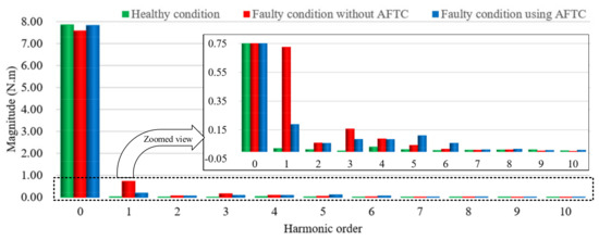
Figure 13.
Comparison of spectrum of torque in healthy, OSF and fault-tolerant conditions.
By comparing the strategies that rely on the fault status or fault categories in advance, the proposed AFTC strategy has superior advantages that lie in there being no need of the prior knowledge of the faults and automatically proceeding with real-time fault detection and fault compensation once the strategy is established.
The two most relevant studies introduced here are given in terms of performance. The iterative learning control (ILC)-based FTC method developed by Mohammadpour et al. [28] is able to suppress around 48.6% of the torque ripples due to the occurrence of an open circuit. Furthermore, a detailed survey of FTC strategies was performed by Xiong et al. [29] who designed an FTC strategy that can reduce the torque ripples by about 54% at maximum. The proposed method can reduce around 60% of torque ripples with an automatic AFTC mechanism. Relative to the ILC compensators [28], the proposed method considers the dynamic performance of the compensation process using a smooth activation mechanism. Compared with the fault-tolerant control strategies in [29], the parameter setting of the proposed method is less complicated to design and simpler to implement in real-time.
As a result, the compensation in current loops can be used for active FTC issues. The experimental tests verify that the proposed strategy is effective to suppress torque ripples in OSF conditions.
5. Conclusions
This paper mainly proposes an AFTC strategy for five-phase trapezoidal PMSG-based tidal current energy applications that are subjected to single switch open circuit fault. This proposed strategy can provide a fault detection and compensation mechanism using generalized proportional integral observers in q-axis current control loops. A full-physical, small-scale power experimental platform is well established to verify the effectiveness and efficiency of this proposed strategy.
The experimental test results show that fault detection is completed with around 1/6 fundamental period. Using a sigmoid function, the close loop system obtains satisfied transient behaviors during the compensation. The experimental tests and spectrum analysis demonstrate that the proposed strategy is easy to implement and can effectively suppress the torque ripples, especially the dominant fluctuation operating at a fundamental frequency. This reinforces the reliability and availability of the whole system. This work will be investigated further in terms of fault-tolerant characteristics of the system at the nonlinear region of the generator’s magnetic curve.
Author Contributions
Z.L. built the experimental platform, developed algorithms, implemented verifications, and wrote this paper; A.H. supported helped for realizations and modifications of paper. M.-F.B. associated the system modelling and the modifications. M.M. evaluated the theory part and gave the modifications; T.T. offered directions of this paper. All authors have read and agreed to the published version of the manuscript.
Funding
This research was funded by China Scholarship Council, Grant No. 201808310083.
Acknowledgments
Here many thanks for the funding and the experimental platform from IREENA laboratory.
Conflicts of Interest
The authors declare no conflict of interest.
Abbreviations
| PMSG | Permanent magnet synchronous generator |
| TCECS | Tidal current energy conversion systems |
| PFTC | Passive fault-tolerant control |
| AFTC | Active fault-tolerant control |
| OSF | Open switch fault |
| GPIO | Generalized proportional integral observer |
| FFs | Form factors |
| MPPT | Maximum power point tracking |
| Back-EMFs | Back-electromagnetic forces |
| TSR | Tip speed ratio |
| DOB | Disturbance observer |
| ESO | Extended state observer |
| SISO | Single input single output |
| FOC | Field-oriented control |
| FFT | Fast Fourier transform |
| DC | Direct current |
| PC | Personal computer |
| ILC | Iterative learning control |
Nomenclatures
| P | Power of tidal current turbine |
| ρ | Density of sea water |
| R | Radius of turbine blade |
| Cp | Power coefficient |
| Cpmax | Maximum power coefficient |
| k | k = 1, 2, 3, 4, 5 for five phases |
| uk | Output voltage of the kth phase |
| ek | Back-EMF of the kth phase |
| ik | Phase current of the kth phase |
| upd | d-axis output of primary sub-machine |
| upq | q-axis output of primary sub-machine |
| usd | d-axis output of secondary sub-machine |
| usq | q-axis output of secondary sub-machine |
| epd | d-axis back-EMF of primary sub-machine |
| epq | q-axis back-EMF of primary sub-machine |
| esd | d-axis back-EMF of secondary sub-machine |
| esq | q-axis back-EMF of secondary sub-machine |
| ipd | d-axis current of primary sub-machine |
| ipq | q-axis current of primary sub-machine |
| isd | d-axis current of secondary sub-machine |
| isq | q-axis current of secondary sub-machine |
| Rs | Phase resistance |
| Rpd | d-axis resistance of primary sub-machine |
| Rpq | q-axis resistance of primary sub-machine |
| Rsd | d-axis resistance of secondary sub-machine |
| x1 | System state |
| Estimate of the system state | |
| x2 | Lumped disturbance state |
| Estimate of lumped disturbance state | |
| Estimate of the third state | |
| n | Order of observer states |
| Estimate of the nth state | |
| Estimate of the system feedback | |
| dl | Lumped disturbance of SISO system |
| Δpara | Term du to parameter variation |
| Δf | Term due to fault occurrence |
| Reference of ipd | |
| Reference of ipq | |
| Reference of isd | |
| Reference of isq | |
| Ω* | Reference speed of generator |
| Γopt | Optimal mechanical torque |
| Reference of electromagnetic torque | |
| Xr | Magnetic ratio between 2 sub-machines |
| dl_pq | q-axis lumped disturbance in ipq loop |
| dl_sq | q-axis lumped disturbance isq loop |
| Δpara_pq | Parameter variation term in ipq loop |
| Δpara_sq | Parameter variation term in isq loop |
| Δf_pq | Term due to fault occurrence in ipq loop |
| Δf_sq | Term due to fault occurrence in isq loop |
| Δnoise_pq | Term of measurement noise in ipq loop |
| Δnoise_sq | Term of measurement noise in isq loop |
| Rs_norminal | Nominal value of phase resistance |
| Lpr_norminal | Nominal value of the input gain b1 |
| Lse_norminal | Nominal value of the input gain c1 |
| Φ1_ norminal | Nominal value of Φ1 |
| Φ3_ norminal | Nominal value of Φ3 |
| xpq1 | System state corresponding to ipq |
| ipq_ff | Form factor of ipq |
| epq | Observer error between and ipq |
| Form factor of | |
| γ | Activation function’s bandwidth coefficient |
| t0 | Starting time of compensation |
| t1 | Ending time of compensation |
| fcnstep | Activation function by a step |
| fcnsigmoid | Activation function by a sigmoid |
| λ | Tip speed ratio |
| λopt | Optimal tip speed ratio |
| β | Pitch angle |
| C1–C6 | Coefficients of function Cp(λ, β) |
| Rsq | q-axis resistance of secondary sub-machine |
| M1 | Adjacent phase mutual inductances |
| M2 | Non-adjacent phase mutual inductances |
| Ls | Self-inductance of phase windings |
| Lpd | d-axis inductance of primary sub-machine |
| Lpq | q-axis inductance of primary sub-machine |
| Lsd | d-axis inductance of secondary sub-machine |
| Lsq | q-axis inductance of secondary sub-machine |
| Lpr | Primary sub-machine inductance |
| Lse | Secondary sub-machine inductance |
| h | The number of harmonic orders |
| θ | Electrical angle |
| p | Number of pole pairs |
| Ω | Measured speed of generator |
| Φh | hth order magnet flux component |
| TPark | Park’s transformation matrix |
| J | Inertia of generator |
| f | Friction of five-phase PMSG |
| Γ | Mechanical torque |
| Γem | Electromagnetic torque |
| Δnoise | Term due to measurement noises |
| a1 | Input gain of SISO system |
| a1_norminal | Nominal value of the input gain a1 |
| b1 | Output gain of SISO system |
| b1_norminal | Nominal value of the input gain b1 |
| c1 | Measurement gain of SISO system |
| c1_norminal | Nominal value of the input gain c1 |
| α1–αn | observer gains for state – |
| ucomp | Compensated output of SISO system |
| fcnact | Activation function |
| Kcomp | Gain of compensator in SISO system |
| Kt | Gain between and |
| Kpwm | Gain of converter model |
| Tpwm | Switching period |
| fpwm | Switching frequency |
| Vcarrier | Amplitude of carrier signals |
| TΩ | Time constant in speed loop |
| τΩ | Sampling delay of speed |
| xsq1 | System state corresponding to isq |
| Estimate of xpq1 | |
| Estimate of xsq1 | |
| xpq2 | Lumped disturbance state in ipq loop |
| xsq2 | Lumped disturbance state in isq loop |
| Estimate of xpq2 | |
| Estimate of xsq2 | |
| Estimate of the third state in ipq loop | |
| Estimate of the third state in isq loop | |
| Estimate of the nth state in ipq loop | |
| Estimate of the nth state in isq loop | |
| αpq1–αpqn | observer gains for state – |
| αsq1–αsqn | observer gains for state – |
| upq_comp | Compensated output in ipq loop |
| usq_comp | Compensated output in isq loop |
| fcnact | Activation function |
| Kpr | Gain of compensator in ipq loop |
| Kse | Gain of compensator in isq loop |
| Vrotor | Regulating voltage of DC motor’s rotor |
| Vstator | Regulating voltage of DC motor’s stator |
Appendix A
Table A1.
Parameters of the full-physical experiment platform.
Table A1.
Parameters of the full-physical experiment platform.
| Symbol | Description | Value/Type |
|---|---|---|
| Pn-gen | Nominal power of five-phase PMSG working at 110 Hz | 3.3 kW |
| f | Friction of five-phase PMSG | 0.123 |
| J | Inertia of generator | 0.00137 kg·m2 |
| Vdc | Voltage in DC link | 100 V |
| Ωn | Nominal speed of generator working at 110 Hz | 2200 rpm |
| p | Number of pole pairs | 3 |
| Φ1, Φ3 | Magnet flux relative to 1st and 3rd harmonics | 0.150 Wb, 0.0149 Wb |
| Rs | Generator stator resistance | 0.540 Ω |
| IGBT module | Power switch module integrated two Infineon IGBTs | Semikron SKM50 GB12T4 |
| Cdc | 4 × (2200 µF/400 V) SKC 2M2 40A-150 | 2.20 mF |
| Load | A resistive load | 242 Ω |
| Lpr | Equivalent inductance of primary sub-machine | 5.1 mH |
| Lse | Equivalent inductance of second sub-machine | 3.2 mH |
| Tpwm | Switching period | 0.1 ms |
| FD | Fault status | 0 (healthy) or 1 (faulty) |
Table A2.
Parameters of fault-tolerant composite controllers in the experimental platform.
Table A2.
Parameters of fault-tolerant composite controllers in the experimental platform.
| Composite Controllers | Symbol | Value |
|---|---|---|
| Speed loop controller | KpΩ | 2.12 |
| KiΩ | 848.85 | |
| Current loop controllers | Kppd, Kppq | 17 |
| Kipd, Kipq | 1800 | |
| Kpsd, Kpsq | 10.67 | |
| Kisd, Kisq | 1800 | |
| αpq1 = αpq2 = αpq3 | 0.9 × 10⁴ | |
| αpq1 = αpq2 = αpq3 | 1.5 × 10⁴ | |
| Kpr, Kse | 0.95 |
References
- Ren, Z.Y.; Wang, Y.M.; Li, H.; Liu, X.; Wen, Y.F.; Li, W.Y. A Coordinated Planning Method for Micrositing of Tidal Current Turbines and Collector System Optimization in Tidal Current Farms. IEEE Trans. Power Syst. 2019, 34, 292–302. [Google Scholar] [CrossRef]
- Sousounis, M.C.; Shek, J.K.H.; Mueller, M.A. Modelling, control and frequency domain analysis of a tidal current conversion system with onshore converters. IET Renew. Power Gen. 2016, 10, 158–165. [Google Scholar] [CrossRef]
- Li, G.J.; Ren, B.; Zhu, Z.Q. Design guidelines for fractional slot multi-phase modular permanent magnet machines. IET Electr. Power Appl. 2017, 11, 1023–1031. [Google Scholar] [CrossRef]
- Barrero, F.; Duran, M.J. Recent Advances in the Design, Modeling, and Control of Multiphase Machines—Part I. IEEE Trans. Ind. Electron. 2016, 63, 449–458. [Google Scholar] [CrossRef]
- Le, Q.D.; Kang, H.-J. Implementation of Fault-Tolerant Control for a Robot Manipulator Based on Synchronous Sliding Mode Control. Appl. Sci. 2020, 10, 2534. [Google Scholar] [CrossRef]
- Halim, A.; Edwards, C.; Chee, P.T. Fault Tolerant Control and Fault Detection and Isolation. In Fault Detection and Fault-Tolerant Control Using Sliding Modes; Advances in Industrial Control; Springer: London, UK, 2011. [Google Scholar]
- Mekri, F.; Ben Elghali, S.; Benbouzid, M.E.H. Fault-Tolerant Control Performance Comparison of Three- and Five-Phase PMSG for Marine Current Turbine Applications. IEEE Trans. Sustain. Energy 2013, 4, 425–433. [Google Scholar] [CrossRef]
- Pham, H.; Bourgeot, J.; and Benbouzid, M. Fault-tolerant finite control set-model predictive control for marine current turbine applications. IET Renew. Power Gener. 2018, 12, 415–421. [Google Scholar] [CrossRef]
- Baudart, F.; Dehez, B.; Matagne, E.; Telteu-Nedelcu, D.; Alexandre, P.; Labrique, F. Torque Control Strategy of Polyphase Permanent-Magnet Synchronous Machines with Minimal Controller Reconfiguration Under Open-Circuit Fault of One Phase. IEEE Trans. Ind. Electron. 2012, 59, 2632–2644. [Google Scholar] [CrossRef]
- Guo, H.; Xu, J.Q. Fault tolerant control with torque limitation based on fault mode for ten-phase permanent magnet synchronous motor. Chin. J. Aeronaut. 2015, 28, 1464–1475. [Google Scholar] [CrossRef][Green Version]
- Lan, J.L. Asymptotic estimation of state and faults for linear systems with unknown perturbations. Automatica 2020, 118, 108955. [Google Scholar] [CrossRef]
- Ortiz-Torres, G.; Castillo, P.; Sorcia-Vázquez, F.D.J.; Rumbo-Morales, J.Y.; Brizuela-Mendoza, J.A.; Cruz-Soto, J.D.L.; Martínez-García, A.M. Fault Estimation and Fault Tolerant Control Strategies Applied to VTOL Aerial Vehicles with Soft and Aggressive Actuator Faults. IEEE Access 2020, 8, 10649–10661. [Google Scholar] [CrossRef]
- Apte, A.A.; Joshi, V.A.; Walambe, R.A.; Godbole, A.A. Speed Control of PMSM Using Disturbance Observer. IFAC PapersOnLine 2016, 49, 308–313. [Google Scholar] [CrossRef]
- Wang, Y.; Yu, H.; Che, Z.; Wang, Y.; Zeng, C. Extended State Observer-Based Predictive Speed Control for Permanent Magnet Linear Synchronous Motor. Processes 2019, 7, 618. [Google Scholar] [CrossRef]
- Ma, Y.; Li, Y. Active Disturbance Compensation Based Robust Control for Speed Regulation System of Permanent Magnet Synchronous Motor. Appl. Sci. 2020, 10, 709. [Google Scholar] [CrossRef]
- Zhu, X.D.; Xia, Y.Q.; Fu, M.Y. Fault estimation and active fault-tolerant control for discrete-time systems in finite-frequency domain. ISA Trans. 2020, 104, 184–191. [Google Scholar] [CrossRef] [PubMed]
- Chen, W.H.; Yang, J.; Guo, L.; Li, S.H. Disturbance-Observer-Based Control and Related Methods—An Overview. IEEE Trans. Ind. Electron. 2016, 63, 1083–1095. [Google Scholar] [CrossRef]
- Wu, C.; Yang, J.; Li, Q. GPIO-Based Nonlinear Predictive Control for Flux-Weakening Current Control of the IPMSM Servo System. Energies 2020, 13, 1716. [Google Scholar] [CrossRef]
- Sun, J.K.; Yang, J.; Zheng, W.X.; Li, S.H. GPIO-Based Robust Control of Nonlinear Uncertain Systems under Time-Varying Disturbance with Application to DC–DC Converter. IEEE Trans. Circuits Syst. II, Exp. Briefs 2016, 63, 1074–1078. [Google Scholar] [CrossRef]
- Jlassi, I.; Estima, J.O.; El Khil, S.K.; Bellaaj, N.M.; Cardoso, A.J.M. A Robust Observer-Based Method for IGBTs and Current Sensors Fault Diagnosis in Voltage-Source Inverters of PMSM Drives. IEEE Trans. Ind. Appl. 2017, 53, 2894–2905. [Google Scholar] [CrossRef]
- Li, H.; and Ren, Z.Y. A Tidal Resource Evaluation-Based Method for Tidal Current Generation Farm Allocation Considering the Directionality of Tidal Currents. IEEE Trans. Sustain. Energy 2020, 11, 2631–2640. [Google Scholar] [CrossRef]
- Xiong, C.; Guan, T.; Zhou, P.; Xu, H. A Fault-Tolerant FOC Strategy for Five-Phase SPMSM with Minimum Torque Ripples in the Full Torque Operation Range Under Double-Phase Open-Circuit Fault. IEEE Trans. Ind. Electron. 2020, 67, 9059–9072. [Google Scholar] [CrossRef]
- Seck, A.; Moreau, L.; Benkhoris, M.F.; Machmoum, M. Control Strategies of Five-phase PMSG-Rectifier under Two Open phase faults for Current Turbine System. In Proceedings of the 2018 IEEE International Power Electronics and Application Conference and Exposition (PEAC), Shenzhen, China, 4–7 November 2018; pp. 1–6. [Google Scholar]
- Nasiri, M.; Milimonfared, J.; Fathi, S.H. Modeling, analysis and comparison of TSR and OTC methods for MPPT and power smoothing in permanent magnet synchronous generator-based wind turbines. Energy Convers. Manag. 2014, 86, 892–900. [Google Scholar] [CrossRef]
- Kestelyn, X.; Semail, E. A Vectorial Approach for Generation of Optimal Current References for Multiphase Permanent-Magnet Synchronous Machines in Real Time. IEEE Trans. Ind. Electron. 2011, 58, 5057–5065. [Google Scholar] [CrossRef]
- Dieng, A.; Benkhoris, M.F.; le Claire, J.C.; Ait-Ahmed, M. Modeling and Optimal Current Control of Five-Phase PMSG—PWM Rectifier SET Non-Sinusoidal EMF Under Open-Circuit Faults. In Proceedings of the 2019 21st European Conference on Power Electronics and Applications (EPE ‘19 ECCE Europe), Genova, Italy, 3–5 September 2019; pp. 1–9. [Google Scholar]
- Siniscalchi, S.M.; Salerno, V.M. Adaptation to New Microphones Using Artificial Neural Networks with Trainable Activation Functions. IEEE Trans. Neural Netw. Learn. Syst. 2017, 28, 1959–1965. [Google Scholar] [CrossRef] [PubMed]
- Mohammadpour, A.; Mishra, S.; Parsa, L. Fault-Tolerant Operation of Multiphase Permanent-Magnet Machines Using Iterative Learning Control. IEEE Trans. Emerg. Sel. Topics Power Electron. 2014, 2, 201–211. [Google Scholar] [CrossRef]
- Xiong, C.; Xu, H.; Guan, T.; and Zhou, P. Fault-tolerant FOC for five-phase SPMSM with non-sinusoidal back EMF. IET Electr. Power Appl. 2019, 13, 1734–1742. [Google Scholar] [CrossRef]


Publisher’s Note: MDPI stays neutral with regard to jurisdictional claims in published maps and institutional affiliations. |
© 2020 by the authors. Licensee MDPI, Basel, Switzerland. This article is an open access article distributed under the terms and conditions of the Creative Commons Attribution (CC BY) license (http://creativecommons.org/licenses/by/4.0/).