Abstract
In this paper, we propose a novel charge-equalization circuit for series-connected batteries. The circuit is composed of an intermediate resonant energy tank, formed by an inductor and a capacitor, and selection switches connected to each battery. The advantage of the proposed circuit is that an exchange of unbalanced charge can be established between any two batteries via the intermediate energy tank. In addition, more than one adjacent battery can serve as a charge-transference party on either side through proper activation of the associated selection switches. Moreover, by virtue of the resonant tank, zero-current switching can be achieved to significantly reduce the transference losses. A laboratory circuit with a control unit was designed for eight 2.5 Ah lithium iron phosphate (LiFePO4) batteries in series. The test results demonstrate that the proposed charge-equalization circuit can realize charge balance effectively. With the charge-equalization circuit, the worst open-circuit voltage difference can be reduced to less than 20 mV under offline conditions, which helps the batteries operate more efficiently.
1. Introduction
Rechargeable batteries have become an integral part of our daily life with the advance of information technology [1]. Lithium-ion batteries, in particular, have been applied in various appliances, ranging from portable devices to high-power electric vehicles and even energy storage systems [2]. However, a single battery cell alone cannot comprehensively cover the range of voltage and power levels [3,4]. Accordingly, numerous battery cells are interconnected in series or parallel to comprise a battery pack, which leads to the charge imbalance issue that frequently accompanies interconnected battery packs. Moreover, a charge imbalance can result in the overcharge/discharge of individual cells, causing the battery’s service capacity and service life to decay and the charge and discharge efficiencies to decline [5,6]. The imbalance problem can deteriorate the battery pack severely since the batteries age differently. Moreover, imbalance precipitates aging. In order to avoid irreversible damage to the battery pack in early stages, many studies on the charge balance circuit have been done [7,8,9].
Charge balance schemes can be divided into ‘passive balance’ and ‘active balance’ schemes. Passive balance consumes energy from the resistors to provide balance, while active balance delivers energy from the capacitors, inductors, or converters [10]. However, the classification of ‘passive’ and ‘active’ is somewhat ambiguous and lacks explanatory power. Here, from the perspective of energy flow between batteries, energy dissipation, energy control, and energy transfer are used to define the charge balance categories shown in Figure 1 [11,12]. In the figure, the “balanced point” denotes the target state-of-charge (SOC) that is shared among the batteries. The red/blue shaped areas indicate the charge that has to be released/accepted from the individual battery to achieve the target. The “energy dissipation” scheme consumes the excess battery energy in the resistors. The “energy control” scheme distributes the charging or discharging currents of each battery through the converters according to the SOC of each battery. The “energy transfer” scheme transfers energy between the unbalanced batteries through the energy storage components to achieve a balanced state.
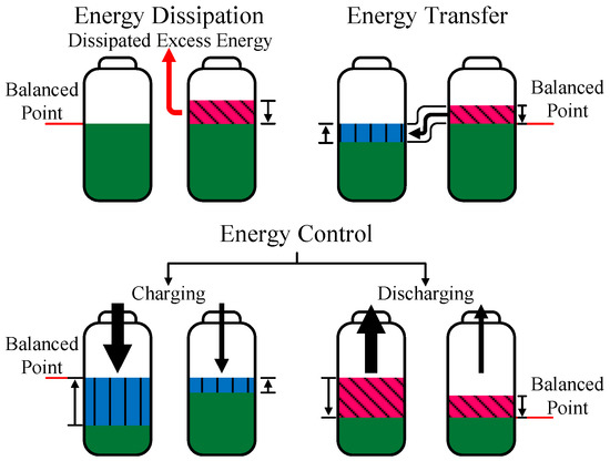
Figure 1.
Schematics for energy dissipation, energy transfer, and energy control.
1.1. Energy Dissipation Circuit
The high-SOC battery dissipates excess charge, denoted as the shaded area, onto some auxiliary components, such as resistors or zener diodes, until its charge is aligned with that of the low-SOC battery. The red arrow indicates that the energy is simply dissipated as heat into the ambience. The energy dissipation scheme is simple and has a low cost [13]. However, the balance efficiency is low and heat management should be considered discretely [14].
1.2. Energy Control Circuit
The energy control circuit adjusts the charging and discharging currents for each battery. To achieve the charge balance, the low-SOC battery is charged with a larger current and vice versa. Conversely, the low-SOC battery is discharged with a smaller current while the high-SOC battery is discharged with a larger current [15]. The black arrows of different thicknesses indicate different current (energy) levels. The energy control circuit’s advantages include high conversion efficiency, less energy circulating into/out of the batteries, and little heat generation; however, the complexity of the control scheme and difficulties with the integrated circuit are shortcomings [16].
1.3. Energy Transfer Circuit
The energy transfer circuit transfers the charge from a high-SOC battery to a low-SOC battery through power converters or storage components. Commonly applied energy transfer circuits include capacitor-type and inductor-type balanced circuits, which have the advantages of a simple structure and a low cost [17]. Through the power switches, the high-SOC battery releases the charge to the capacitor or the inductor, while the low-SOC battery receives the charge in order to balance the charge. However, a surge in the current or voltage will occur at the switches, reducing their reliability. Moreover, if the energy is not transferred to adjacent batteries, sequences of transfers are required, resulting in an accumulation of energy losses [18,19]. In light of the employment of inductor and capacitor (LC) components, with the inductor’s ability to suppress the current ripple as well as the capacitor’s ability to retard the voltage spike, the authors in [20,21] propose an efficient approach to charge equalization with the energy transfer circuit for series-connected batteries.
As there is a positive correlation between battery voltage and SOC, we use the terms ‘battery voltage’ and ‘battery SOC’ interchangeably in this paper. An intermediate energy storage tank is composed of an inductor and a capacitor. By activating the appropriate selection switches, the battery with the highest SOC in the pack can transfer the excess charge to the LC energy tank. Subsequently, as the battery with the lowest SOC is connected to the energy tank, the voltage gap between the capacitor and the battery will complete the transfer of unbalanced charge. As a result, the process for balancing the highest- and lowest-SOC batteries can be established using only two charge transference procedures. In addition, zero-current switching (ZCS) can be achieved to effectively reduce the switching losses at the selection switches. Our experimental results demonstrate that the voltage difference can be reduced to less than 20 mV by the proposed circuit and the balance strategy.
2. Proposed Charge-Equalization Circuit
Figure 2 shows the proposed charge-transfer balance circuit with an LC intermediate resonant energy tank. The proposed circuit is inspired by the switched-capacitor method, whose main problems are high current spikes and an elongated balancing time. As a result, the resonant energy tank, which is composed of an inductor Lr and a capacitor Cr, is capable of suppressing the surges in the current and the voltage, respectively [22,23,24]. A total of n batteries are connected in series to form the battery pack. Each battery, e.g., the kth, can be attached to the resonant tank by its associated AC switches, i.e., Ska, Skb and Skc, and Skd. The power switches are referred to as ‘selection switches’ here because they are responsible for sifting out a specific battery or even adjacent batteries to mount on the intermediate energy tank and process the charge transfer. Moreover, as the resonant current rewinds back to zero, the selection switches secure the breach to turn ZCS off, reducing the switching loss.
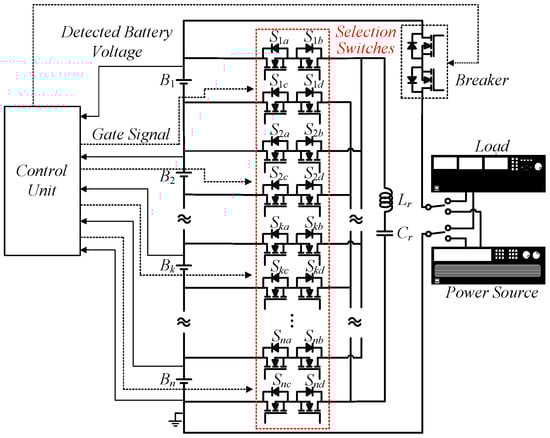
Figure 2.
The proposed charge-equalization circuit.
The circuit has no impact on the charging/discharging functions; that is, charge equalization can be performed concurrently as the AC breaker on the main charge/discharge path is closed. The control of the activation of selection switches and the breaker can be integrated into and performed by a control unit.
The elongated balancing time issue arises from the diminished battery voltage difference as balance processing, which degrades the charge transference current. When the battery voltage difference is relatively large, the capacitor’s voltage, which is a replica of the high-SOC battery’s voltage, is sufficiently higher to transfer charge to the low-SOC battery in a one-to-one battery charge transfer. However, as the battery voltage difference gradually diminishes, the balance current decreases accordingly. To solve this problem, in this paper we propose an enhanced balance mode. Two adjacent batteries are connected in series to replenish the capacitor, which in turn increases the balance capacity.
To illustrate the circuit’s operation, we take the highest voltage battery Bi and the lowest voltage battery Bj as examples to perform an operation mode analysis. The on-state resistance of the selection switches and the stray resistances through the current’s path are aggregated into a lumped resistance Rs.
2.1. Normal Balance Mode
Normal balance mode features a one-to-one energy transfer between batteries. Figure 3 shows the theoretical waveforms. vBi and vBj are the instantaneous voltages of Bi and Bj. Six and Sjx are the switches connected to Bi and Bj, respectively, where x denotes a, b, c, and d. vix and vjx are the gating signals controlling the power switches Six and Sjx, respectively. We use the exaggeratedly diminished voltage difference to illustrate that the transferred charges Q1 and Q2, which represent the accumulated charging/discharging current, are reduced greatly when the voltage difference nearly vanishes, i.e., the ability to transfer charge is becoming limited. The small voltage difference is also the reason for the decreases in iL and vc. According to the switching actions of the selection switches, the charge transfer is decomposed into four intervals. Figure 4 depicts the current conduction path of each interval.
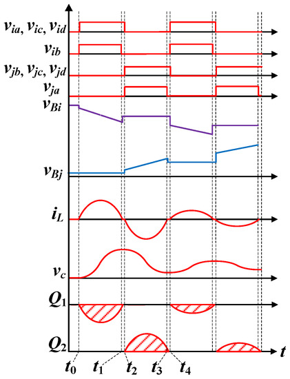
Figure 3.
The theoretical waveforms of the normal balance mode.
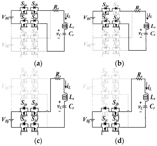
Figure 4.
The circuit’s operation in normal balance mode: (a) Interval I; (b) Interval II; (c) Interval III; (d) Interval IV.
2.1.1. Interval I (t0 ≤ t < t1)
Interval I begins when the selection switches attached to battery Bi, i.e., Sia, Sib, Sic, and Sid, are turned on. The voltage equation can be expressed as:
Before the selection switches are turned on, iL is zero. Therefore, the current can be expressed as follows:
where Vc0 is the capacitor’s voltage at t0, α is the damping factor and is expressed as α = Rs/2Lr, and ωd is the damped natural frequency, which can be expressed as:
Here, the resonance is assumed to be underdamped due to the low stray resistance. The resonant current, iL, is transferred from Bi to the capacitor, and the capacitor’s voltage can be expressed as:
To prevent iL flowing back to the battery Bi, switch Sib is turned off at t1 to block the reverse current path.
2.1.2. Interval II (t1 ≤ t < t2)
In this interval, Sib is turned off and iL continuously charges capacitor Cr via the antiparallel diode of Sib. As iL decreases to zero, the other switches Sia, Sic, and Sid can turn ZCS off, ending this interval.
2.1.3. Interval III (t2 ≤ t < t3)
Interval III starts when the selection switches, Sja, Sjb, Sjc, and Sjd, are turned on. Battery Bj closes the voltage loop and is characterized as:
The resonant current reverses and charges the battery Bj, which is expressed as:
where Vc2 is the capacitor’s voltage at t2.
The voltage across the capacitor can be expressed as:
Similarly, switch Sja is turned off earlier to prevent the current flow from being reversed.
2.1.4. Interval IV (t3 ≤ t < t4)
This interval is followed by the switch Sja being turned off. The resonant current charges Bj through the antiparallel diode of Sja. When the resonance current reaches zero, the entire charge transfer cycle is completed.
2.2. Enhanced Balance Mode
Figure 5 shows the theoretical waveforms of the enhanced balance mode, which describe the energy transfer between two series-connected batteries and another battery. vkx are the gating signals to the power switches skx. Given that Bi has the highest voltage, and j = I ± 1, then Bj is adjacent to Bi. The two batteries collaboratively discharge to the lowest-voltage battery Bk. Due to the nearly doubled charging voltage of Cr, iL and vc are only slightly affected and Q1 and Q2 are degraded only a little, even when the difference between VBi and VBk is small.
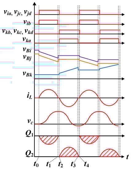
Figure 5.
The theoretical waveforms of the enhanced balance mode.
Figure 6 shows the circuit configuration and the selection switches. The positive and negative arms of the series-connected batteries are turned on to charge Cr through Lr and Rs. After the charging phase of Cr is complete, the selection switches change states to transfer the charge to Bk and complete the transfer.
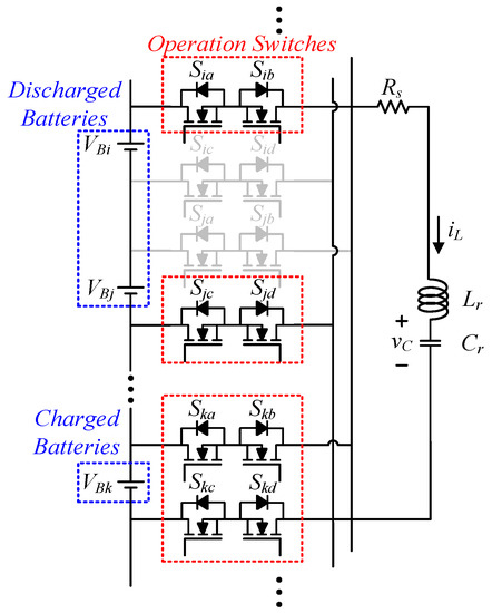
Figure 6.
The circuit’s operation in enhanced mode.
3. Balance Strategy
Figure 7 shows the control flowchart for the balance strategy. At the beginning, the voltages of each cell in the battery pack are collected and sorted. When the voltage difference between the highest-voltage battery and the lowest-voltage battery is greater than 20 mV, the battery pack is tagged as unbalanced and the balance procedure is initiated.
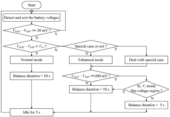
Figure 7.
Flowchart for the balance strategy.
At the beginning, the question of whether normal mode or enhanced mode should be adopted is determined by the voltage difference between the highest-voltage battery and the lowest-voltage battery. To ensure a sufficiently high balance current, a boundary threshold voltage, Ven, is preset. If the voltage difference is greater than Ven, normal mode is adopted; otherwise, enhanced mode is adopted.
Figure 8 shows the loaded voltage and temperature waveforms of the experimental lithium iron phosphate batteries (LiFePO4) over the accumulated charge during constant current–constant voltage (CC-CV) charging and CC discharging, which are standard charging and discharging methods [25]. Lithium iron phosphate batteries are relatively safe and thermally stable and have a long lifecycle and high power density [26]. Obviously, there is a flat-voltage region (approximately between 3.3 and 3.4 V in the figure). Outside of this flat-voltage region, the loaded voltage varies swiftly over the accumulated charge.
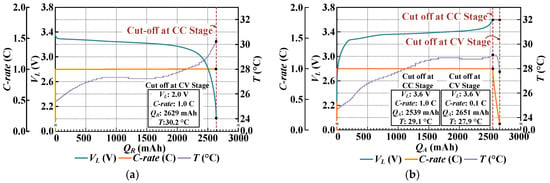
Figure 8.
Waveforms of the loaded voltage, current, and temperature during standard charging and discharging of LiFePO4 batteries: (a) discharging; (b) charging.
As shown in Figure 7, after the decision is made on the appropriate operation mode, the charge-equalization circuit operates for a few seconds, which is hereafter referred to as the ‘balance duration,’ to balance the batteries. However, due to the sharp deviation in voltage when the battery’s voltage is outside the flat-voltage region, the balance duration should be limited. As a result, when the enhanced mode is adopted, i.e., there is a sufficiently high transference current, as well as a less than 200 mV voltage difference under the condition that the battery’s voltage is outside the flat-voltage region, the balance duration needs to be shortened to 5 s to prevent the dramatic variation in the battery’s voltage. Finally, the balance circuit idles for 5 s to wait for the battery’s voltage to rebound in order to ensure accurate detection.
Special Case
There is a special case that should be considered when using the enhanced mode. This case is when B1 or Bn, one of the two geographical extremes of the battery string, is the highest-voltage battery while its adjacent neighbor, B2 or Bn−1, happens to be the lowest-voltage battery. In this case, the operation is different during charging and discharging. During charging, the highest- and lowest-voltage batteries are connected together to transfer the charge to the battery with the second-lowest voltage, which extends the charging time. In contrast, during discharging, in order to prolong the usage time, the battery with the second-highest voltage works together with the adjacent battery, depending on which neighbor possesses the higher voltage, to transfer the charge to the lowest-voltage battery.
4. Experimental Results
We performed offline and online balancing experiments with eight 2.5 Ah LiFePO4 batteries in series, whose total rated voltage is 25.6 V, to verify the proposed balance circuit and strategy.
4.1. Parameters
In order to employ a medium capacitor, a switching frequency, fsw, of 4.15 kHz was chosen to transfer electric charge between batteries and the intermediate energy tank. Since the resonant frequency should be slightly higher than the switching frequency, it was set to 5 kHz. Furthermore, the balance circuit requires both the maximum and minimum charge-transfer currents to be limited. Therefore, under these three specifications, the resonant tank can be accordingly designed. As a result, the following equation can be formulated:
where fr is the resonant frequency.
The maximum average current can be calculated within half of the resonant cycle. Simplifying (2) and (6) by approximating e−αt as (1 − αt) and averaging the discharging and charging currents, the average currents Idisch and Ich can be expressed as:
where Vc0 is assumed to be 0 V to obtain the maximum value of Ich, Vc2 is approximated as double the discharged battery voltage, and Rs is aggregated to be 0.5 Ω.
When substituting the possible maximum VBi with two fully charged series of cells, that is, 3.6 × 2 V, and taking the minimum VBj to be (3.6 − Ven) V and Vc2 to be 14.4 V in the above equations, Ich and Idisch should be less than 3.75 A (equivalent to 1.5 C). On the other hand, to prevent the transfer current from being too low, under the condition of VBi and Vc2 being 3.6 V and 7.2 V, respectively, Ich and Idisch should be greater than 1.25 A, i.e., 0.5 C.
Obviously, Ich is the critical threshold in (8) and (9). Ven was calculated to be 800 mV, which was used as the watershed between normal balance mode and enhanced balance mode in the balance strategy. Accordingly, Cr was calculated to be 16 μF. However, since 16 μF is not an off-the-shelf specification, 20 μF was applied. Consequently, the inductor was set to 50 μH. The circuit parameters for the experiments are listed in Table 1.

Table 1.
Circuit parameters.
4.2. Experimental Waveforms
Figure 9a,b shows the inductor current and capacitor voltage waveforms in the normal mode and the enhanced mode, respectively. According to the experimental waveforms, zero-current switching is achieved by the characteristics of the LC resonant tank. Moreover, no current surge was detected. It is worth noting that iL and vc are larger in the enhanced mode than in the normal mode, indicating that more energy can be transferred in a cycle.
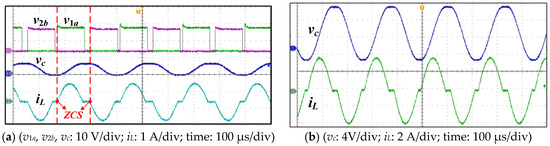
Figure 9.
Experimental waveforms: (a) normal balance mode; (b) enhanced balance mode.
4.3. Experimental Result: Offline Balancing
Figure 10 shows the voltages of the batteries in the pack during offline balancing; that is, with no charging/discharging current flowing through the entire pack. Table 2 summarizes the initial and balanced voltages of each battery in the pack. The initial maximum and minimum voltages are 3.075 V (VB7) and 2.170 V (VB2), respectively, with a voltage difference of 905 mV. At the beginning, the voltage difference is greater than 800 mV and, as expected, the normal mode is entered into to transfer electric charge from battery B7 to battery B2, which results in the observed voltage fluctuation in both batteries. After 30 s, the maximum voltage difference between batteries shrinks to less than 800 mV, triggering the enhanced mode.

Figure 10.
Battery voltage variations during offline balancing.
Table 2.
Battery voltages during offline balancing.
At 185 s, VB7 is the highest voltage (2.941 V), while VB1 is the lowest (2.742 V). Since the voltage difference is lower than 200 mV, the balance duration is reduced to 5 s to avoid overcharging and over-discharging. This is the reason why the battery voltage varies more rapidly after this instant.
At around 482 s, the peak and valley voltages are 2.788 V and 2.737 V, respectively, corresponding to a 15 mV difference. Since the voltage difference is less than 20 mV, the balance circuit is inactivated.
4.4. Experimental Result: Discharging
Figure 11a,b shows the battery voltages when the battery pack is discharged by a 1.5 A current with or without activation of the balance circuit. In Figure 11a, the voltages undulate due to the balance operation. In contrast, Figure 11b shows smooth voltage variations. As demonstrated in Table 3, the initial battery voltages are adjusted to be as similar as possible in both cases. When B8 in Figure 11a and B2 in Figure 11b satisfy the discharging cut-off condition, 2 V, the discharging operation stops.
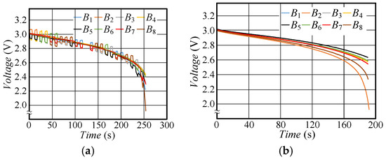
Figure 11.
Variation in voltage when discharging: (a) with balancing; (b) without balancing.
Table 3.
Battery voltage during discharging with and without the balance operation.
With the balance operation, the discharging operation lasts for 254 s, whereas the discharging time without the balance operation is only 190 s, which is about 60 s shorter. Moreover, the final pack voltages are 18.803 V with the balance operation and 19.914 V without the balance operation. These results show that the energy of a battery pack can be better utilized by employing the proposed balance operation.
4.5. Experimental Result: Charging
Figure 12a,b shows the fluctuation in the battery voltages with/without the balance operation under a 1.5 A charging current. Table 4 shows the voltages in both cases. As B5 and B7 satisfy the cut-off condition, 3.6 V, the circuit operation terminates. With the balance operation, the total charging time is 360 s. However, without the balance operation, the charging time is only 100 s, meaning that less charge can be transferred to the battery pack. Moreover, the final pack voltages are 28.328 V with the balance operation and 27.866 V without the balance operation. Again, these results indicate that the balance circuit can help to optimize the charge storage capability of a battery pack.
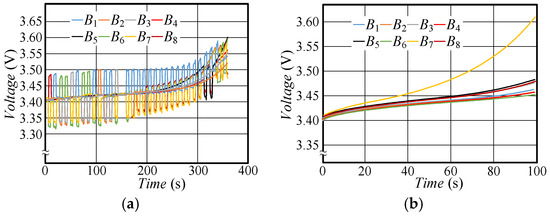
Figure 12.
Variation in voltage when charging: (a) with balancing; (b) without balancing.
Table 4.
Battery voltages when charging with/without the balance operation.
4.6. Experimental Result: Special Case
Figure 13a,b presents the experimental results of balancing in the special case. Table 5 lists the voltage of each battery in this case. It can be noticed that the highest-voltage battery is B8 with 3.425 V, and its adjacent battery B7 has the lowest voltage of 3.303 V. As a result, the battery that is to receive the charge shifts from the one with the lowest voltage to the one with the second-lowest voltage, B1. According to the figure, it is obvious that B7 and B8 collaboratively charge B1. On the other hand, similar to the results of the previous experiments, the charging time of the battery pack without the balance operation is less than that of the battery pack with the balance operation.
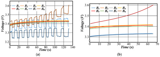
Figure 13.
Variation in the voltage in the special case: (a) with balancing; (b) without balancing.
Table 5.
Battery voltages in the special case.
4.7. Comparison with Other Methods
Table 6 presents a comparison between the proposed method and some existing methods dedicated to balancing charge. It can be observed that a current spike occurred with the capacitor-type balance method, which is a severe problem because it might damage the components [27]. As for the component count, the number of required capacitors and inductors increases as the number of batteries increases for the inductor-type balance method [28]. For the proposed circuit, only one capacitor and one inductor are needed no matter how many batteries there are. Another important point is that the charge transfer path of the proposed method can directly transfer charge between any two batteries compared with the other types of balance circuits, which not only reduces unnecessary switching loss but also shortens the balance duration.
Table 6.
Comparison with existing methods.
5. Conclusions
In this study, we proposed a charge-equalization circuit composed of an intermediate resonant energy tank to transfer unbalanced charge between batteries connected in series. The operation and the circuit parameters were determined according to the preset requirements. When the battery pack is charging or discharging, the balance operation may not finish because the charging or discharging cut-off conditions have been satisfied. As expected, the experimental results show that the proposed balance circuit can help the battery pack to fully utilize its available capacity.
Consequently, the proposed circuit enables batteries connected in series to transfer the charge from any number of adjacent batteries to any other number of adjacent batteries. Moreover, during a transfer of charge, the potential for current surges is eliminated due to the characteristics of LC resonance, and the switching loss is also minimized. Furthermore, we proposed an enhanced balance mode to sustain a sufficient amount of balance current. Our experimental results show that the voltage difference can be shrunk to less than 20 mV during offline balancing. As for online operation, balance during discharging can increase the load usage time, while balance during charging is able to increase the total charge of the battery pack. Finally, a comparison with the capacitor-type and inductor-type balance methods was carried out to demonstrate that the proposed balance circuit has the advantage of no current or voltage spikes. Moreover, the proposed balance method not only possesses the benefits of less components when balancing a large number of batteries, but also the shortest charge transfer path, which can shorten the balance time and decrease transfer loss.
Author Contributions
Conceptualization, Y.-C.H. (Yao-Ching Hsieh); methodology, Y.-C.H. (Yao-Ching Hsieh) and P.-C.C.; software, P.-C.C.; validation, Y.-C.H. (Yao-Ching Hsieh), Y.-C.H. (You-Chun Huang) and P.-C.C.; formal analysis, Y.-C.H. (Yao-Ching Hsieh); investigation, Y.-C.H. (Yao-Ching Hsieh); resources, Y.-C.H. (Yao-Ching Hsieh); data curation, Y.-C.H. (Yao-Ching Hsieh) and P.-C.C.; writing—original draft preparation, Y.-C.H. (You-Chun Huang); writing—review and editing, Y.-C.H. (Yao-Ching Hsieh) and Y.-C.H. (You-Chun Huang); visualization, Y.-C.H. (You-Chun Huang) and P.-C.C.; supervision, Y.-C.H. (Yao-Ching Hsieh) and Y.-C.H. (You-Chun Huang); project administration, Y.-C.H. (You-Chun Huang); funding acquisition, Y.-C.H. (Yao-Ching Hsieh) All authors have read and agreed to the published version of the manuscript.
Funding
This research was funded by MOST 108-2221-E-110-040, MOST 109-3116-F-006-020-CC1, and MOST 109-2221-E-110-026.
Conflicts of Interest
The authors declare no conflict of interest.
References
- Huang, W.; Abu Qahouq, J.A. Energy Sharing Control Scheme for State-of-Charge Balancing of Distributed Battery Energy Storage System. IEEE Trans. Ind. Electron. 2015, 62, 2764–2776. [Google Scholar] [CrossRef]
- Xiong, R.; Zhang, Y.; Wang, J.; He, H.; Peng, S.; Pecht, M. Lithium-Ion Battery Health Prognosis Based on a Real Battery Management System Used in Electric Vehicles. IEEE Trans. Veh. Tech. 2019, 68, 4110–4121. [Google Scholar] [CrossRef]
- Alramlawi, M.; Li, P. Design Optimization of a Residential PV-Battery Microgrid with a Detailed Battery Lifetime Estimation Model. IEEE Trans. Ind. Appl. 2020, 56, 2020–2030. [Google Scholar] [CrossRef]
- Hannan, M.A.; Hoque, M.M.; Ker, P.J.; Begum, R.A.; Mohamed, A. Charge Equalization Controller Algorithm for Series-Connected Lithium-Ion Battery Storage Systems: Modeling and Applications. Energies 2017, 10, 1390. [Google Scholar] [CrossRef]
- Baronti, F.; Roncella, R.; Saletti, R. Performance Comparison of Active Balancing Techniques for Lithium-ion Batteries. J. Power Sources 2014, 267, 603–609. [Google Scholar] [CrossRef]
- Xiong, H.; Fu, Y.; Dong, K. A Novel Point-to-Point Energy Transmission Voltage Equalizer for Series-Connected Supercapacitors. IEEE Trans. Vehicular Tech. 2016, 65, 4669–4675. [Google Scholar] [CrossRef]
- Lambert, S.M.; Pickert, V.; Atkinson, D.J.; Zhan, H. Transformer-Based Equalization Circuit Applied to n-Number of High Capacitance Cells. IEEE Trans. Power Electron. 2016, 31, 1334–1343. [Google Scholar] [CrossRef]
- Cao, X.; Zhong, Q.; Qiao, Y.; Deng, Z. Multilayer Modular Balancing Strategy for Individual Cells in a Battery Pack. IEEE Trans. Energy Convers. 2018, 33, 526–536. [Google Scholar] [CrossRef]
- Nazi, H.; Babaei, E.; Sabahi, M. Bidirectional Active Charge Equaliser for Series-Connected Cells. IET Power Electron. 2019, 12, 1229–1240. [Google Scholar] [CrossRef]
- Wu, T.-H.; Moo, C.-S. State-of-Charge Estimation with State-of-Health Calibration for Lithium-Ion Batteries. Energies 2017, 10, 987. [Google Scholar]
- Wu, T.-H.; Moo, C.-S.; Hou, C.-H. A Battery Power Bank with Series-Connected Buck–Boost-Type Battery Power Modules. Energies 2017, 10, 650. [Google Scholar] [CrossRef]
- Varnosfaderani, M.A.; Strickland, D. Online Impedance Spectroscopy Estimation of a Dc–dc Converter Connected Battery Using a Switched Capacitor-based Balancing Circuit. J. Eng. 2019, 2019, 4681–4685. [Google Scholar] [CrossRef]
- Omariba, Z.B.; Zhang, L.; Sun, D. Review of battery cell balancing methodologies for optimizing battery pack performance in electric vehicles. IEEE Access 2019, 7, 129335–129352. [Google Scholar] [CrossRef]
- Park, H.; Kim, C.; Kim, C.; Moon, G.; Lee, J. A Modularized Charge Equalizer for an HEV Lithium-Ion Battery String. IEEE Trans. Ind. Electron. 2009, 56, 1464–1476. [Google Scholar] [CrossRef]
- Kutkut, N.H.; Wiegman, H.L.N.; Divan, D.M.; Novotny, D.W. Design considerations for charge equalization of an electric vehicle battery system. IEEE Trans. Ind. Appl. 1999, 35, 28–35. [Google Scholar] [CrossRef]
- Gottwald, T.; Ye, Z.; Stuart, T. Equalization of EV and HEV batteries with a ramp converter. IEEE Trans. Aerosp. Electron. Syst. 1997, 33, 307–312. [Google Scholar] [CrossRef]
- Liu, L.; Sun, W.; Han, P.; Mai, R.; He, Z.; Li, W. Design of Zero-Current Parallel-Switched-Capacitor Voltage Equalizer for Battery Strings. In Proceedings of the 2019 IEEE Applied Power Electronics Conference and Exposition (APEC), Anaheim, CA, USA, 17–21 March 2019. [Google Scholar]
- Cui, X.; Shen, W.; Zhang, Y.; Hu, C. A Novel Active Online State of Charge Based Balancing Approach for Lithium-Ion Battery Packs during Fast Charging Process in Electric Vehicles. Energies 2017, 10, 1766. [Google Scholar] [CrossRef]
- Wu, S.-L.; Chen, H.-C.; Chien, C.-H. A Novel Active Cell Balancing Circuit and Charging Strategy in Lithium Battery Pack. Energies 2019, 12, 4473. [Google Scholar] [CrossRef]
- Sung, C.-H.; Lee, K.; Kang, B. Voltage Equalizer for Li-ion Battery String Using LC Series Resonance. In Proceedings of the IECON 2013-39th Annual Conference of the IEEE Industrial Electronics Society, Vienna, Austria, 10–13 November 2013. [Google Scholar]
- Lee, K.; Chung, Y.; Sung, C.; Kang, B. Active Cell Balancing of Li-Ion Batteries Using LC Series Resonant Circuit. IEEE Tran. Ind. Electron. 2015, 62, 5491–5501. [Google Scholar] [CrossRef]
- Shang, Y.; Cui, N.; Zhang, Q.; Zhang, C. A Battery Equalizer with Zero-current Switching and Zero-Voltage Gap among Cells Based on Three-resonant-state LC Converters. In Proceedings of the 2017 IEEE Applied Power Electronics Conference and Exposition (APEC), Tampa, FL, USA, 26–30 March 2017. [Google Scholar]
- Cui, N.; Shang, Y.; Zhang, Q.; Zhang, C. A Direct Multi-Cells-to-Multi-Cells Equalizer Based on LC Matrix Converter for Series-Connected Battery Strings. In Proceedings of the 2018 IEEE Applied Power Electronics Conference and Exposition (APEC), San Antonio, TX, USA, 4–8 March 2018; Volume 33, pp. 680–683. [Google Scholar]
- Shang, Y.; Zhang, C.; Cui, N.; Guerrero, J.M. A Cell-to-Cell Battery Equalizer with Zero-Current Switching and Zero-Voltage Gap Based on Quasi-Resonant LC Converter and Boost Converter. IEEE Trans. Power Electron. 2015, 30, 3731–3747. [Google Scholar] [CrossRef]
- Liu, P.; Chien, L. A High-Efficiency Integrated Multimode Battery Charger with an Adaptive Supply Voltage Control Scheme. IEEE Trans. Power Electron. 2018, 33, 6869–6876. [Google Scholar] [CrossRef]
- Zhang, X.; Peng, H.; Wang, H.; Ouyang, M. Hybrid Lithium Iron Phosphate Battery and Lithium Titanate Battery Systems for Electric Buses. IEEE Trans. Veh. Technol. 2018, 67, 956–965. [Google Scholar] [CrossRef]
- Hsieh, Y.; Cai, Z.; Wu, W. Switched-capacitor Charge Equalization Circuit for Series-connected Batteries. In Proceedings of the 2014 International Power Electronics Conference (IPEC-Hiroshima 2014-ECCE ASIA), Hiroshima, Japan, 18–21 May 2014. [Google Scholar]
- Moo, C.S.; Hsieh, Y.C.; Tsai, I.S.; Cheng, J.C. Dynamic Charge Equalization for Series-connected Batteries. IEE Proc. Elect. Power Appl. 2003, 150, 501–505. [Google Scholar] [CrossRef]
Publisher’s Note: MDPI stays neutral with regard to jurisdictional claims in published maps and institutional affiliations. |
© 2020 by the authors. Licensee MDPI, Basel, Switzerland. This article is an open access article distributed under the terms and conditions of the Creative Commons Attribution (CC BY) license (http://creativecommons.org/licenses/by/4.0/).