Abstract
Aiming at the problems of large excitation loss and low power generation efficiency of silicon rectifier generators and the unstable output voltage of permanent magnet (PM) generators, a hybrid excitation generator (HEG) with suspended brushless claw pole electrical excitation rotor (EER) and combined magnetic pole PM rotor is proposed in the present work. With only one fractional slot winding stator, the generator adopts PM field as the main magnetic field and electrical excitation field as the auxiliary magnetic field, which not only retains the advantages of high efficiency of PM generators but also effectively reduces excitation consumption. The main structure parameters and the design method were analyzed, and a simulation analysis of no-load magnetic field distribution and flux regulation ability was carried out using finite element software to verify the rationality of the hybrid excitation parallel magnetic circuit design. Moreover, the no-load, load, regulation, and voltage regulation characteristics of the designed generator were tested, and the results show that the designed generator has a wide range of voltage regulation, which can ensure stable output voltage under variable speed and load conditions.
1. Introduction
At present, silicon rectifier generators are widely used in vehicle generators. However, their thermal effect of electric excitation winding consumes a lot of heat energy, so their power generation efficiency is low. In contrast, permanent magnet (PM) generators use PM steel to generate the main magnetic field, which has the advantages of high power density and high output efficiency. However, it is difficult for the output voltage to be stable due to the nonadjustable PM field [1,2,3,4]. Therefore, based on the power demand of modern vehicles, hybrid excitation generators (HEGs), which use the two excitation methods together to generate a magnetic field, not only combine the advantages of the two generators but can also overcome the defects to a certain extent. Therefore, they have gradually become the development trend of vehicle generators for the future [5,6,7,8,9]. Experts and scholars from home and abroad have invested in research in this field, and the structure and voltage stabilizing performance of HEGs have been continuously improved and innovated. The authors of [10] proposed a parallel HEG consisting of a PM rotor and a doubly salient electrical excitation rotor (EER). In this, the output voltage of the generator is provided by two armature windings in series, and the electric excitation winding of the doubly salient EER is wound in the stator slot of the corresponding stator. In [11], a brushless hybrid excitation direct current generator composed of a structure-parallel PM part and a flux modulation part was proposed, and the operation mode of the flux modulation part was fully analyzed under different conditions. This structure can reduce the short-circuit current by adjusting the electrical excitation current (EEC), but the double stator and double armature winding structure increases the length of the two ends of the middle part and the axial length of the generator. In [12] and [13], the authors researched a HEG with a PM rotor and a magnetic shunt rotor. In this structure, a special magnetic bridge is used to transfer the magnetic field in the electric excitation part, which increases the additional air gap as well as the axial length of the generator. The authors of [14] proposed a built-in PM and salient pole electrical excitation HEG with stator skew. Here, the electric excitation part of the structure is the salient pole type, and it needs to use the structure of a carbon brush slip ring, which will affect the service life of the generator. In terms of voltage control, on the basis of the traditional electronic control system, some improved voltage stabilizing control system with neural network control, robust control, and sliding mode control were proposed in [15,16,17], respectively, and achieved good voltage stabilizing performance.
To sum up, researchers have carried out in-depth research on parallel-structure HEGs and achieved certain research results that provide useful reference for the research and development of high-performance HEGs [18,19,20,21,22,23,24]. On this basis, this paper proposes a HEG with suspended brushless claw pole EER and combined magnetic pole PM rotor coaxially connected in parallel and sharing the same armature winding. The generator uses the PM field as the main magnetic field to improve the power density and the electrical excitation field as the auxiliary magnetic field to reduce the excitation loss. Meanwhile, the brushless claw pole rotor eliminates the easily damaged carbon brush slip ring structure, which can effectively improve the reliability of the generator.
2. Design and Calculation of HEG
In the design structure of HEG, the PM part is the main magnetic potential source and the electrical excitation part plays an auxiliary regulating role. Therefore, the design power of the PM part and the electrical excitation part are 700 and 300 W, respectively. The structure of the designed HEG is shown in Figure 1, and its main technical indexes are shown in Table 1.
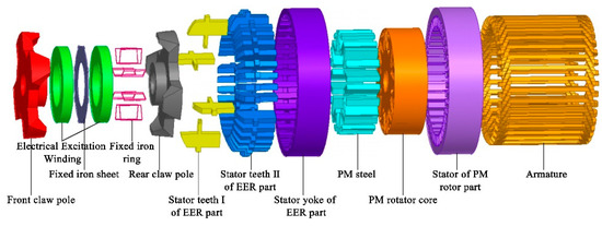
Figure 1.
Structure diagram of hybrid excitation generator (HEG).

Table 1.
Main technical indexes of HEG.
2.1. The EER Rotor of HEG
In the EER, the electric excitation winding is fixed by a fixed iron ring, and the outer side of that ring is welded on the stator. The claw part is shortened on both sides so as to avoid sweeping the chamber when the rotor rotates. The installation diagram of EER and the corresponding stator is shown in Figure 2, and the dimensions of the designed claw pole structure are shown in Figure 3.
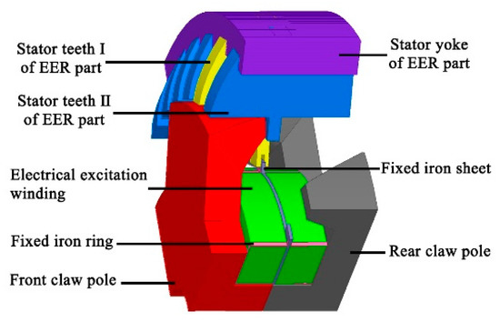
Figure 2.
The installation diagram of electrical excitation rotor (EER) and corresponding stator.
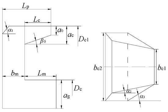
Figure 3.
Parameter dimension diagram of claw pole structure.
The thickness of flange plate , the yoke diameter , and the thickness of claw root determine the magnetic flux of the claw pole and the material consumption, which are important parameters of the claw pole structure, and can be calculated as follows [25,26,27]:
where is the inner diameter of stator; is the axial length of EER; is the magnetic flux density of the claw pole body; is the magnetic flux density of the main air gap; is the magnetic flux leakage coefficient of EER; is the pole distance of the generator; is the length of the main air gap; is the pole pairs; is the claw pole calculation coefficient, which is usually taken as 1 to 1.2; is the thickness of the tip of the claw; is the length of the claw, and is the inclination angle of the claw, which is usually taken as 10 to 15°.
By calculation, the parameter dimensions of EER are shown in Table 2.
Table 2.
The parameter dimensions of EER.
The diameter of the bare wire of electric excitation winding is determined by EEC and EEC density, and the diameter of the enameled wire is selected according to the winding standard of the generator based on the diameter of the bare wire. The diameter of the bare wire of winding can be calculated as follows:
where is the EEC, is the EEC density, and we selected = 10 . From this calculation, we can get = 0.637 mm, and referring to the enameled wire diameter standard, we selected = 0.67 mm.
2.2. The PM Rotor of HEG
The PM rotor adopts a combined magnetic pole with radial V-shaped PM steel and rectangular PM steel to provide the magnetic flux of each pole. It has a significant “magnetic gathering” effect and can effectively improve the main magnetic flux of each pole and avoid the sag of output voltage peak [28]. In order to prevent magnetic flux leakage, arc-shaped magnetic separation grooves are set on both ends of the PM steel. The structure of the combined PM rotor is shown in Figure 4.
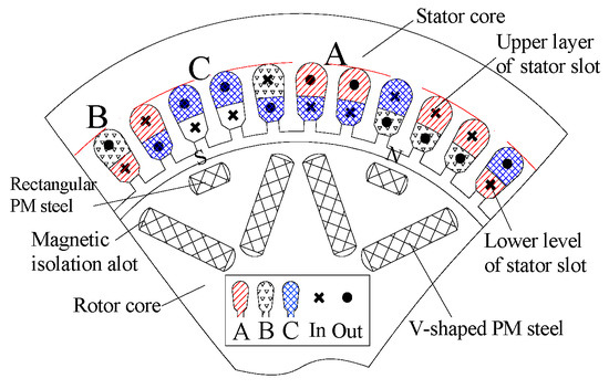
Figure 4.
Structure diagram of combined pole permanent magnet (PM) rotor.
In order to improve the magnetic field strength, the Nd-Fe-B PM material NTB35 with high remanence induction strength, high coercivity, and high magnetic energy product is adopted. Its remanence induction strength is 1.17 T, the maximum coercivity is 836 , and the maximum magnetic energy product is 263 . According to the dimensional constraint equation of PM steel, the main dimension of PM steel can be calculated as follows [29]:
where is the magnetizing direction length of PM steel; is the width of PM steel; is the relative recovery permeability; is the residual magnetic induction strength of PM steel at working temperature; is the axial length of PM steel; is the polar arc coefficient; and is the axial length of the PM rotor.
The parameter dimensions of PM steel were calculated according to the calculation and are shown in Table 3.
Table 3.
The parameter dimensions of PM steel.
2.3. Stator of HEG
The stator core is made of a 0.5 mm silicon steel sheet, which can effectively reduce the stator eddy current loss and magnetic flux leakage [30]. In order to match the brushless design of EER, the stator is a combined stator with the same slot moment, tooth width, and yoke length, as shown in Figure 5. It can be seen that the stator of the EER part is welded by radial stator teeth and tangential stator yoke in order to cooperate with it. The PM rotor part adopts a semiclosed rectangular slot, and its structural parameters are shown in Figure 6.

Figure 5.
Structure diagram of combined stator.

Figure 6.
Parameter dimension diagram of rectangular slot stator.
The stator tooth width and the height of stator yoke determine the stator slot area and the flux density of stator teeth and stator yoke, which are important structural parameters of stator slot and can be calculated as follows:
where is the height of the stator slot; is the height of the stator slot wedge; is the number of stator slots; is the flux density of the stator teeth and = 1~1.3; is the lamination coefficient of stator lamination, and in this paper, = 0.95; is the calculation coefficient of the stator slot and is usually taken as 0.358 to 0.37; and is the flux density of the stator yoke. The calculated stator tooth width is 3.9 mm and the height of the stator yoke is 7 mm.
The armature winding is designed as three-phase, eight-pole, 36-slot fractional slot winding, which can effectively weaken the high-order harmonics and reduce the sinusoidal distortion rate of the output voltage waveform [31,32,33]. According to the 40° slot angle and 60° phase band, the vector coils of each phase winding are distributed as shown in Table 4. The winding schematic diagram of fractional slot winding can be seen in Figure 4.
Table 4.
The vector coil distribution table of each phase winding.
The number of conductors in series for each phase of the armature winding is determined by the line load of generator , and it can be calculated as follows:
where is the phase number of generator, and is the rated current of the generator.
Moreover, the number of conductors per slot can be calculated as follows:
where is the number of parallel branches.
The number of turns in each phase of the double-layer winding is half of the number of conductors in each slot, and we calculated as 8 turns.
3. Magnetic Field Simulation Analysis and Output Characteristic Analysis
3.1. The Finite Element Simulation Model
The normal operation of a vehicle generator meets the Maxwell’s equation [34]:
where is the vector magnetic potential and , where , , and are the components of on each coordinate axis; is the current density vector and , where , , and are the components of on each coordinate axis; and is the permeability and , where , , and are the components of on each coordinate axis.
By solving the formula, the partial differential equations can be obtained as follows:
Therefore, the flux density of any point in the magnetic field and the magnetic flux of any surface can be obtained as follows:
From the above calculation, under certain boundary conditions, the vector magnetic potential of any point in the generator magnetic field can be obtained by solving Maxwell’s equations. The magnetic flux density of this point can be calculated using the vector magnetic potential, and the magnetic flux of a certain plane can be solved.
3.2. Simulation Analysis of Magnetic Field
The simulation analysis model of HEG was established using finite element software. After simulation, the magnetic density cloud diagram of HEG was obtained, as shown in Figure 7.

Figure 7.
Magnetic density map of HEG. (a) magnetic density map in the direction of PM rotor, (b) magnetic density map in the direction of EER.
It can be seen from Figure 7 that the synthetic magnetic field of the generator is evenly distributed. The maximum flux density of the main flux magnetic circuit is less than 2 T, so the magnetic field is not saturated. There are a lot of magnetic field saturation phenomena at the air gap between the two ends of the PM steel, which is the main leakage flux distribution area. Those saturations can effectively reduce the magnetic flux loss, guide the magnetic flux to converge into the main flux magnetic circuit, improve the magnetic field gathering effect, and enhance the magnetic field strength.
According to the model simulation analysis, when the EEC is 0, +3, and −3 A, the vector distribution of magnetic flux density of the generator and the radial magnetic density in the main air gap are shown in Figure 8, Figure 9 and Figure 10.
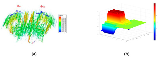
Figure 8.
Magnetic field distribution of HEG when electrical excitation current (EEC) is 0 A: (a) vector distribution of magnetic flux density; (b) axial distribution of radial magnetic density in the main air gap.

Figure 9.
Magnetic field distribution of HEG when EEC is +3 A: (a) vector distribution of magnetic flux density; (b) axial distribution of radial magnetic density in the main air gap.
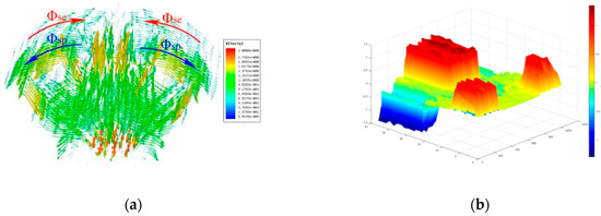
Figure 10.
Magnetic field distribution of HEG when EEC is −3 A: (a) vector distribution of magnetic flux density; (b) axial distribution of radial magnetic density in the main air gap.
In Figure 8, Figure 9 and Figure 10, the Φsp is the PM flux and the Φse is the electrical excitation flux. Figure 8 shows that when the EEC is 0 A, the electrical excitation field is almost zero and the radial magnetic density of the main air gap corresponding to the EER is almost zero too. At this time, the main magnetic field of the generator is only provided by the PM field, and it is weak. As shown in Figure 9, when the EEC is 3 A in the forward direction, the generated electrical excitation field is not zero. It is in parallel with the PM field in the rotor part and synthesized in the main air gap, and the direction is the same as that of the PM field. The radial magnetic density distribution shows that the electrical excitation part and the PM part have the same direction under the same polarity. The peak magnetic flux density of the PM part is about 1.2 T, and the electrical excitation part is about 0.9 T. Meanwhile, the magnetic flux of the main air gap is mainly provided by the PM field, and the electrical excitation field plays the role of “enhancing magnetic field”. As shown in Figure 10, when the EEC is 3 A in negative direction, the direction of the electrical excitation field is opposite to that of the PM field, and the radial flux density of the main air gap of the electrical excitation field is opposite to that of the PM field part under the same polarity. At this time, the magnetic density of the main air gap is the difference between the two parts. The electrical excitation field plays a role of “weakening magnetic field”, which can effectively weaken the synthetic magnetic field and reduce the output voltage.
From the above analysis, it can be concluded that changing the direction of the EEC can change the direction of the electrical excitation field so as to achieve the purpose of adjusting the size of the main magnetic field and make the output voltage of the HEG stable in a certain range.
3.3. The Output Characteristic Analysis
The output characteristics of the newly developed HEG were tested and analyzed, and the no-load characteristics of the HEG under rated speed of 4000 r/min is shown in Figure 11.
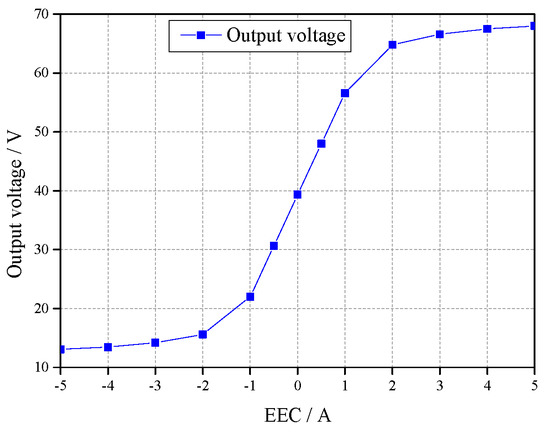
Figure 11.
No-load characteristic curve of HEG.
Figure 11 shows that when the EEC increases from 0 to 5 A, the generator output voltage increases from 39.32 to 68.25 V, an increase of 73.5%. When the EEC is between −2 and 2 A, the output voltage increases linearly with increasing EEC. However, when the EEC is greater than 2 A or less than −2 A, the electrical excitation field gradually tends to be saturated, and the regulation ability to the main air gap magnetic field is weakened. Thus, the growth trend of the output voltage is obviously weakened. Moreover, it can be seen that the output voltage can be changed within 12–68 V by changing the magnitude and direction of EEC, so the generator has a wide range of voltage regulation.
Figure 12 shows the changes in output voltage when the EEC changes from 0 to 3.5 A and the generator speed changes from 500 to 4500 r/min.
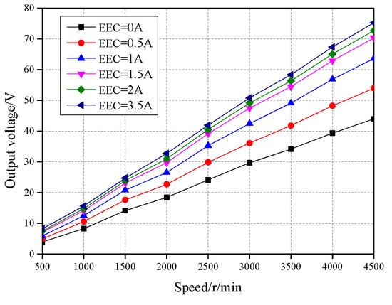
Figure 12.
Output voltage variation curve under variable speed and variable EEC conditions.
It can be seen from Figure 12 that the output voltage increases almost linearly with the increase in speed, no matter how large the EEC is. When the EEC is 2 A and the speed changes from 500 to 4500 r/min, the output voltage increases from 7 to 72 V. When the speed is 4500 r/min and the EEC is 0 A, the output voltage is 44 V, which is reduced by 39%. Therefore, changing the size of the EEC can effectively change the output voltage. Figure 13 shows the external characteristics of the generator when it is connected with pure resistive load and operates at rated speed of 4000 r/min.
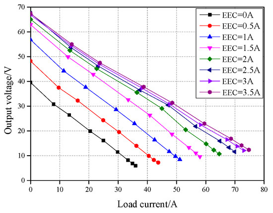
Figure 13.
The external characteristic curve of HEG.
Figure 13 shows that the output voltage decreases with the increase in load current when the generator operates with load and the speed remains unchanged. When the load current is the rated load current of 71.4 A, the EEC needs to be greater than 3 A. The power characteristics of the generator were calculated and are shown in Figure 14.

Figure 14.
Power characteristic curve of HEG.
From the Figure 14, it can be seen that when the speed is 4000 r/min, the peak load power is 1521 W. Under the rated load current condition, when the EEC is 3 A, the output power is 980 W, so the rated output power can be reached by adding a little EEC.
When the generator runs at rated speed, the regulation characteristics of the generator can be obtained by changing the load and adjusting the EEC to stabilize the output voltage at 14 V. In order to study the output characteristics of the designed HEG, the regulation characteristics of the designed HEG and the traditional silicon rectifier generator were compared and studied, and the results are shown in Figure 15.
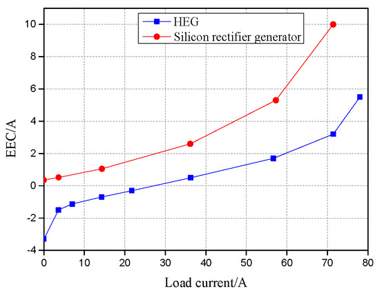
Figure 15.
Regulation characteristics of HEG and silicon rectifier generator.
Figure 15 shows that with the increase in load current, the greater the power required by the generator, the greater is the EEC. When the load current is in the range of 7 to 71.4 A, the EEC increases almost linearly, which indicates that the generator has good regulation characteristics. When the load current is 21.7 A, the load power of the generator is 304 W and the EEC is −0.3 A. At this time, the electrical excitation field and the PM field are reversed, and the composite magnetic field is weakened. Moreover, with the decrease in load current, the EEC will always decrease to ensure the output voltage. And with the increase in load current, in order to maintain the stability of the generator output voltage, both the HEG and the silicon rectifier generator need to increase EEC. However, the EEC required by the HEG is far less than that by the silicon rectifier generator, so it can avoid large excitation heating and loss and has higher output efficiency and wider voltage adjustment range. It can also be seen from the figure that under the condition of rated load current, the EEC of the silicon rectifier generator needs to be connected with 10 A, but the HEG only needs 3.2 A to ensure stable voltage output.
After installing voltage regulator controller for the generator, the voltage stabilizing performance test was carried out under the load power of 980, 1000, and 1020 W. The results are shown in Table 5.
Table 5.
Test results of voltage stabilizing performance of the HEG.
As shown in Table 5, when the speed changes from 2000 to 4800 r/min and the load power changes from 950 to 1050 W, the output voltage is stable between 12.01 and 14.23 V, which shows that the designed HEG has a good voltage stabilizing effect.
4. Conclusions
In this work, we studied a HEG for vehicles that consists of a combined rotor with brushless claw pole EER and combined PM rotor in coaxial parallel as well as a double-layer fractional slot winding stator. The main structure parameters were analyzed and calculated in detail, and magnetic field simulation and output characteristic analysis were carried out. The results show that the magnetic field distribution is uniform, the main magnetic circuit flux is not saturated, and the designed magnetic circuit is reasonable. Changing the magnitude and direction of the EEC can effectively change the size of the main air gap magnetic field and stabilize the output voltage. Under rated load conditions, the generator can output a stable voltage and has a wide voltage regulation range and good regulation characteristics. Moreover, under variable speed and load conditions, the output voltage of the generator can be stabilized between 12.01 and 14.23 V, which indicates that the HEG has good voltage stability.
Author Contributions
Conceptualization, H.G. and X.Z.; validation, H.G., Y.L., and X.X.; investigation, A.W. and S.W.; resources, H.G.; data curation, H.G., W.H., and Y.Z.; writing—original draft preparation, H.G. and X.Z.; writing—review and editing, H.G., Y.L., and X.X.; visualization, W.H., A.W., and Y.Z.; supervision, X.Z. and L.S.; project administration, X.Z. and L.S.; funding acquisition, X.Z. and L.S. All authors have read and agreed to the published version of the manuscript.
Funding
This research was funded by the National Natural Science Foundation of China, grant number (51875327 and 51975340).
Conflicts of Interest
The authors declare that there is no conflict of interest.
References
- Aladsani, A.S.; Beik, O. Characterization of a Hybrid PM Generator Using a 32-phase Brushless Excitation Scheme. IEEE Trans. Energy Convers. 2019, 34, 1391–1400. [Google Scholar] [CrossRef]
- Wardach, M.; Bonislawski, M.; Palka, R.; Paplicki, P.; Prajzendanc, P. Hybrid Excited Synchronous Machine with Wireless Supply Control System. Energies 2019, 12, 3153. [Google Scholar] [CrossRef]
- Wang, D.; Zhang, D.; Xue, D.; Peng, C.; Wang, X. A New Hybrid Excitation Permanent Magnet Machine with an Independent AC Excitation Port. IEEE Trans. Ind. Electron. 2019, 66, 5872–5882. [Google Scholar] [CrossRef]
- Zhang, X.; Zhao, X.; Niu, S. A Novel Dual-Structure Parallel Hybrid Excitation Machine for Electric Vehicle Propulsion. Energies 2019, 12, 338. [Google Scholar] [CrossRef]
- Ye, C.; Du, Y.; Yang, J.; Liang, X.; Xiong, F.; Xu, W. Research of an Axial Flux Stator Partition Hybrid Excitation Brushless Synchronous Generator. IEEE Trans. Magn. 2018, 54, 1–4. [Google Scholar]
- Zhu, H.; Hu, Y. Research on Operation Principle and Control of Novel Hybrid Excitation Bearingless Permanent Magnet Generator. Energies 2016, 9, 673. [Google Scholar] [CrossRef]
- Yao, S.; Zhang, W. Stator Tooth Shape Optimization for Double Salient Hybrid Excitation Generator Based on Asymmetric Circuit Analysis. Compel Int. J. Comput. Math. Electr. 2019, 38, 1738–1755. [Google Scholar] [CrossRef]
- Mykola, O.; Vadim, C.; Eugene, M. Ouput Voltage Stabilization Process Simulation in Generator with Hybrid Excitation at Variable Drive Speed. In Proceedings of the 2019 IEEE 2nd Ukraine Conference on Electrical and Computer Engineering (UKRCON), Lviv, Ukraine, 2–6 July 2019; pp. 310–313. [Google Scholar]
- Gu, X.; Zhang, Z.; Sun, L.; Yu, L. Phase Displacement Characteristics of a Parallel Hybrid Excitation Brushless DC Generator. IEEE Trans. Energy Convers. 2020, 35, 875–885. [Google Scholar] [CrossRef]
- Wu, Y.; Sun, L.; Zhang, Z.; Miao, Z.; Liu, C. Analysis of Torque Characteristics of Parallel Hybrid Excitation Machine Drives With Sinusoidal and Rectangular Current Excitations. IEEE Trans. Magn. 2018, 54, 1–5. [Google Scholar] [CrossRef]
- Zhang, Z.; Yu, L.; Dai, C.; Yan, Y. Investigation and Development of a New Brushless DC Generator System for Extended-Range Electric Vehicle Application. In IEEE Energy Conversion Congress & Exposition (ECCE); IEEE: Piscataway, NJ, USA, 2014; pp. 3155–3162. [Google Scholar]
- Zhang, Z.; Dai, J.; Dai, C.; Yan, Y. Design Considerations of a Hybrid Excitation Synchronous Machine with Magnetic Shunt Rotor. IEEE Trans. Magn. 2013, 49, 5566–5573. [Google Scholar] [CrossRef]
- Zhang, Z.; Yan, Y.; Yang, S.; Bo, Z. Principle of Operation and Feature Investigation of a New Topology of Hybrid Excitation Synchronous Machine. IEEE Trans. Magn. 2008, 44, 2174–2180. [Google Scholar] [CrossRef]
- Malanciuc, A.; Simion, A.; Livadaru, L.; Munteanu, A.; Afanasov, C. FEM-based Analysis of a Hybrid Synchronous Generator with Skewed Stator Slots. Adv. Electr. Comput. Eng. 2011, 11, 9–14. [Google Scholar] [CrossRef]
- Thammasiriroj, W.; Nuchkrua, T.; Ruayariyasub, S. Sliding Mode Control for Stabilizing DC-Link of DC-DC Converter in Photovoltaic Systems. In Proceedings of the 2nd International Symposium on Power Electronics for Distributed Generation Systems, Hefei, China, 16–18 June 2010; pp. 347–351. [Google Scholar]
- Dong, Y.; Nuchkrua, T.; Shen, T. Asymptotical Stability Contouring Control of Dual-Aarm Robot with Holonomic Constraints: Modified Distributed Control Framework. IET Control Theory Appl. 2019, 13, 2877–2885. [Google Scholar] [CrossRef]
- Zidani, Y.; Zouggar, S.; Elbacha, A. Steady-State Analysis and Voltage Control of the Self-Excited Induction Generator Using Artificial Neural Network and an Active Filter. Iran. J. Sci. Technol. Trans. Electr. Eng. 2018, 42, 41–48. [Google Scholar] [CrossRef]
- Popenda, A.; Chwalba, S.; Sowiński, J. The Synchronous Generator Based on a Hybrid Excitation with the Extended Range Of Voltage Adjustment. E3S Web Conf. 2019, 84, 1–7. [Google Scholar] [CrossRef]
- Zhu, S.; Liu, C.; Wang, K.; Yuan, X.; Hu, Y.; Ning, Y. Magnetic Field Distribution and Operating Characteristics of a Hybrid Excitation Generator Based on Integrated Brushless Excitation. IEEE Trans. Magn. 2016, 52, 1–12. [Google Scholar] [CrossRef]
- Wang, H.; Zhang, F.; Guan, T.; Yu, S. Equivalent circuit and characteristic simulation of a brushless electrically excited synchronous wind power generator. Front. Mech. Eng. 2017, 12, 420–426. [Google Scholar] [CrossRef]
- Zhu, C.; Wang, X.; Zhao, W.; Yang, Y.; Yu, P. Performance Analysis on a Surface-mounted Permanent Magnet Synchronous Generator with Hybrid Excitation based on Equivalent Magnetic Circuit. In Proceedings of the 2019 22nd International Conference on Electrical Machines and Systems (ICEMS), Harbin, China, 11–14 August 2019; pp. 1–5. [Google Scholar]
- Zhang, X.; Du, Q.; Xu, J.; Zhao, Y.; Ma, S. Development and Analysis of the Magnetic Circuit on Double-Radial Permanent Magnet and Salient-Pole Electromagnetic Hybrid Excitation Generator for Vehicles. Chin. J. Mech. Eng. 2019, 32, 100–112. [Google Scholar] [CrossRef]
- Sun, L.; Zhang, Z.; Yu, L.; Gu, X. Development and Analysis of a New Hybrid Excitation Brushless DC Generator With Flux Modulation Effect. IEEE Trans. Ind. Electron. 2019, 66, 4189–4198. [Google Scholar] [CrossRef]
- Zhu, S.; Liu, C.; Wang, K.; Hu, Y.; Ning, Y. Theoretical and Experimental Analyses of a Hybrid Excitation Synchronous Generator with Integrated Brushless Excitation. IET Electr. Power Appl. 2016, 10, 258–267. [Google Scholar] [CrossRef]
- Zhang, X.; Du, Q.; Ma, S.; Geng, H.; Hu, W.; Li, Z.; Liu, G. Permeance Analysis and Calculation of the Double-Radial Rare-Earth Permanent Magnet Voltage-Stabilizing Generation Device. IEEE Access 2018, 6, 23939–23947. [Google Scholar] [CrossRef]
- Xia, Y.; Wen, Z.; Zhu, Z.; Zhong, S.; Chen, Y.; Zhang, J. Research on a Hybrid Excitation PM Synchronous Generator with Stator Third Harmonic Winding Excitation. IET Electr. Power Appl. 2020, 14, 418–425. [Google Scholar] [CrossRef]
- Zhu, C.; Yang, Y.; Jiang, B.; Zhang, G.; Yu, P. Equivalent Magnetic Circuit Analysis of a Novel Brushless Hybrid Excitation Synchronous Generator. In Proceedings of the 2018 21st International Conference on Electrical Machines and Systems (ICEMS), Jeju, Korea, 7–10 October 2018; pp. 458–462. [Google Scholar]
- Hu, W.; Zhang, X.; Yin, H.; Geng, H.; Zhang, Y.; Shi, L. Analysis of Magnetic Field and Electromagnetic Performance of a New Hybrid Excitation Synchronous Motor with dual-V type Magnets. Energies 2020, 13, 1501. [Google Scholar] [CrossRef]
- Zhang, X.; Du, Q.; Ma, C.; Ma, S.; Xu, J.; Geng, H.; Tian, G. Nd-Fe-B Permanent Magnet Generator and Voltage Stabilizing Control Technology for Vehicles. Adv. Mech. Eng. 2016, 8, 1–11. [Google Scholar] [CrossRef]
- Yu, L.; Zhang, Z.; Sun, L.; Yan, Y. A Split-Field-Windings Doubly Salient Brushless DC Generator with Reduced Excitation Capacity for Hybrid Electric Vehicles. IEEE Trans. Ind. Electron. 2018, 65, 7697–7708. [Google Scholar] [CrossRef]
- Kanti, R.T.; Apel, M.M.; Oo, A.M. Robust Adaptive Backstepping Excitation Controller Design for Higher-Order Models of Synchronous Generators in Multimachine Power Systems. IEEE Trans. Power Syst. 2018, 34, 40–51. [Google Scholar]
- Wang, Y.; Niu, S.; Fu, W. A Novel Dual-Rotor Bidirectional Flux-Modulation PM Generator for Stand-Alone DC Power Supply. IEEE Trans. Ind. Electron. 2019, 66, 818–828. [Google Scholar] [CrossRef]
- Aladsani, A.S.; Beik, O. Design of a Multiphase Hybrid Permanent Magnet Generator for Series Hybrid EV. IEEE Trans. Energy Convers. 2018, 33, 1–9. [Google Scholar]
- Zhao, X.; Niu, S.; Ching, T. Design and Analysis of a New Brushless Electrically Excited Claw-Pole Generator for Hybrid Electric Vehicle. IEEE Trans. Magn. 2018, 54, 1–5. [Google Scholar] [CrossRef]
© 2020 by the authors. Licensee MDPI, Basel, Switzerland. This article is an open access article distributed under the terms and conditions of the Creative Commons Attribution (CC BY) license (http://creativecommons.org/licenses/by/4.0/).