Abstract
In solar-powered wireless sensor networks (SP-WSNs), the best use of harvested energy is more important than minimizing energy consumption since energy can be supplied periodically. Meanwhile, as is well known, the reliability of the communication between sensor nodes is very limited due to the resource constraints of sensor nodes. In this paper, we propose an efficient forward error correction (FEC) scheme which can give solar-powered wireless sensor networks more reliable communication. First, the proposed scheme provides energy-adaptive operation for the best use of solar energy. It calculates the amount of surplus energy which can be used for extra operations and then determines the number of additional parity bits for FEC according to this amount of surplus energy. At the same time, it also provides a link quality model that is used to calculate the appropriate number of parity bits for error recovery required for the current data communication environment. Finally, by considering these two parity sizes, it is possible to determine the number of parity bits that can maximize the data reliability without affecting the blacking out of nodes. The evaluation of the performance of the approach was performed by comparing the amount of data collected at the sink node and the number of blackout nodes with other schemes.
1. Introduction
A wireless sensor network (WSN) is composed of multiple wireless sensor nodes and is generally used to obtain environmental data, such as temperature, humidity and pressure, in a specific region. It is used in various fields [1,2], including military operations, environmental monitoring and agriculture, to acquire data in hard-to-reach areas [3,4,5].
However, because a wireless sensor node has limited hardware performance, the energy capacity of the battery is insufficient. For this reason, many techniques have been studied to minimize the energy consumption of WSNs in various computer science research fields (e.g., networks, systems, security, and databases) [6,7,8]. Recently, studies on energy-harvesting nodes, in which nodes use rechargeable batteries that can be charged using energy sources in surrounding environments, have been conducted extensively [9,10,11]. Among these nodes, the solar-powered wireless sensor node is the most useful because solar energy has a high power density and is predictable, owing to its periodicity [12]. If more energy is collected than the battery capacity of a solar-powered node, the harvested energy can be disposed of; conversely, if the energy consumption in the node is higher than the harvested energy, the energy can be exhausted, and the node can be blacked out. Therefore, in solar-powered WSNs (SP-WSN), the focus should be on maximizing energy use so that no energy is disposed of due to battery capacity and the nodes never run out of power [13,14,15]. It should be noted that only the schemes that minimize energy consumption have been studied in existing battery-powered sensor networks; therefore, the schemes for the SP-WSN are distinct from other previous schemes in terms of energy usage.
To handle data transmission errors that occur in a network environment, automatic repeat request (ARQ) schemes or forward error correction (FEC) schemes are generally used. The ARQ is a scheme for retransmitting data when an acknowledgment is not received within a particular time frame after data transmission; in contrast, the FEC transmits additional parity bits by encoding original data when transmitting and corrects errors by decoding parity bits in the receiver. In a WSN environment, which consists of resource-constrained nodes, the performance of the radio transceiver is also limited [9], which causes frequent communication errors. The ARQ causes many retransmissions when errors occur frequently, thus consuming a large amount of energy for data transmission. In contrast, the FEC scheme corrects errors by using parity bits that are sent with the data; therefore, it does not require retransmission. However, this scheme requires additional data processing overheads to manipulate parities. In general, the energy consumption for data processing is significantly less than that for data transmission [16] in wireless communication. Therefore, the FEC, which does not require the retransmission of data, is better suited than the ARQ to WSN environments, owing to its low energy consumption [17].
It is important to note that the reliability of the communication and energy consumption are in a trade-off relationship. For FEC, the error correction rate increases in proportion to the size of the parity bits; therefore, it is possible to ensure the high reliability of data communication by increasing the parity size. However, the parity size must be limited because more energy is required to send and receive data as the parity size increases, as the parity bits piggy-back on the data packet. For this reason, studies on the use of FEC schemes for reliable data communication while reducing energy consumption have been conducted [18,19]. Angelin et al. [20] proposed an energy model of the sensor node which can derive a reasonable number of parity bits, in terms of energy.
However, the link quality should also be considered when determining the size of parity bits. Assuming that the channel condition is good, a small amount of parity is sufficient, even if the amount of energy is adequate. In this case, it is useful to save the energy consumed by the FEC and use the saved energy to improve other types of quality of service (QoS, e.g., the duty-cycle, sensing rate and routing). On the contrary, if the channel condition is poor, a longer parity should be used, regardless of the energy status. Therefore, an appropriate length of the parity, in terms of the channel condition and available energy, should be considered for reliable data communication in FEC.
In this study, we propose an enhanced FEC scheme, tailored for SP-WSNs, which considers both energy and channel conditions simultaneously to determine the parity size. Based on the FEC model [21] and solar-energy model (energy harvest and consumption model), the parity candidates that the node can use without power outages are calculated. Simultaneously, based on the channel state model, the best parity size among the parity candidates is selected for reliable communication. As a result, the proposed scheme enables reliable communication with a minimum blackout time for each node. The contributions of the proposed scheme are summarized in Figure 1.
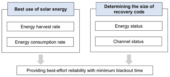
Figure 1.
Contributions of the proposed scheme [22].
This paper is structured as follows: In Section 2, we introduce the latest research related to the SP-WSNs and the FEC scheme. In Section 3, the operation algorithm of the proposed scheme is described in detail. In Section 4, we evaluate the performance of the proposed method and analyze the results. Finally, Section 5 presents the conclusions of this study.
2. Related Work
2.1. WSN Technologies
In general, two main categories of networks are used for WSNs: short-range low-power networks and long-range low-power networks. ZigBee and 6LoWPAN are considered to be representative protocols for the former networks; on the other hand, LoRaWAN and SigFox are two major protocols for the latter networks, which are often called low-power wide-area networks (LPWAN).
ZigBee and 6LoWPAN are designed for low data-rate and battery-powered applications. They are currently the most popular, low-cost, low-power wireless mesh networking standards on the market. They are typically implemented for short-range (10–75 m) networks or in a wireless mesh for networks that operate over longer ranges. Although ZigBee defines the communication between 802.15.4 nodes, which means ZigBee devices can interoperate with only other ZigBee devices, 6LoWPAN offers interoperability with not only 802.15.4 devices but also with devices on any other IP network link (e.g., Ethernet or WiFi). A benefit of ZigBee, however, is that nodes can stay in sleep mode for most of the time, drastically extending battery life.
LPWANs, including LoRaWAN and SigFox, are a type of wireless wide-area network designed to allow long-range communications at a low bit rate among sensors. These networks consist of four elements: an end node (end point), gateway (base station), network server and end-user application (device application) [23]. The architecture of an LPWAN is a star topology where gateways are transparent bridges between end nodes and the network server. End nodes are connected to the network server by a single-hop wireless communication (LoRa RF and SigFox LTN radio ), while gateways are connected to the network server by backhaul (cellular, WiFi, Ethernet or satellite). Recently, many papers have reviewed [24,25,26] and evaluated different LPWAN technologies for WSNs.
The main difference between a short-range low-power network and an LPWAN is the transmission distance. In the case of the former, the distance is 10–100 m, whereas it is 5–50 km for the latter. Another difference is the communication path between nodes. In the former, the host (end) node can communicate with other host nodes directly. In the latter, however, end nodes can communicate only with gateways, and they cannot send packets directly to other end nodes. Therefore, Zigbee and 6LoWPAN usually comprise a mesh topology while LoRaWAN and SigFox mainly operate through a star topology.
The proposed scheme is designed for an WSN based on short-range low-power mesh networks.
2.2. SP-WSNs
WSNs are primarily deployed in harsh natural environments that are inaccessible to people and are used for military, ecological surveillance and disaster detection. In conventional WSNs, battery-based wireless sensor nodes, which have limited lifetimes, are generally used. Therefore, this type of WSN cannot operate if all its nodes exhaust the energy they had at the time of deployment. To overcome this limitation, studies have been conducted on sensor nodes that can harvest environmental energy, using rechargeable batteries, to enable nodes to operate permanently [9,27]. Energy harvesting refers to the conversion of energy from the environment to electrical energy, using sources such as the sun, wind and vibration [11,28,29]. Among various energy sources, solar energy has the highest energy density, as shown in Table 1. Moreover, it has periodicity, which means that a new supply of solar energy can be expected during every harvesting cycle (one day) [12]. Thus, solar energy is widely employed in WSNs.

Table 1.
Characteristics of various environmental energy sources [9].
Figure 2 [22] shows the amount of solar energy harvested per day over time. This is the result of experiments with two 105 W poly crystalline cells type of solar panels and a 12 V 98 Ah sealed gel rechargeable battery. As shown in Figure 2, about 30 Ah is collected per day on average. A low-end laptop operating as a sensor node is connected to this harvesting system, the average power consumption of which is about 10 W. It can be confirmed that the harvested solar energy satisfies the amount of energy required by the sensor node. For another example, in the case of Heliomote, which is one of the well-known solar-powered nodes, the energy harvested during the day is 1140 mWh on average [30]. Since the energy consumed by a typical sensor node is about 15 mW, it can be seen that a sufficient amount of energy is harvested to operate without blackout during a day.
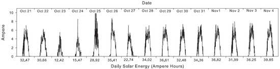
Figure 2.
Amount of energy harvested by an energy-harvesting node [22].
Even with its relative abundance, there are times of the day when solar energy will not be available; thus, there is a need for energy storage that balances the energy stored with the consumption rate of the sensor node. The storage devices could be either rechargeable batteries or supercapacitors. Rechargeable batteries are preferred in WSNs due to their high energy density [31,32]; these include Ni-MH and lithium ion/polymer rechargeable batteries, both of which have their own advantages and disadvantages. The energy densities of Ni-MH batteries are typically 60–80 Wh/kg, while those of lithium rechargeable batteries could be as high as 120–140 Wh/kg. Ni-MH batteries are rated for 300–500 cycles, while lithium batteries are rated for 500–1000 cycles, but their lifetime decreases with frequent charge/discharge cycles. Even with the higher cycle efficiency of lithium rechargeable batteries, they are limited to a shorter lifetime as the electrolyte decays, causing an increase in the internal resistance; this causes the stored energy to be unable to be discharged.
Supercapacitors are alternatives to using rechargeable batteries. Supercapacitors usually have an energy density of 1–10 Wh/kg, which is lower than the rechargeable batteries but sufficiently high for applications in WSN. Additionally, they have 100,000 recharge cycles with a 10-year functioning lifetime before the energy stored is reduced by 20% [33] and have a relatively small size. Therefore, supercapacitors have become more useful because of the high density of energy stored, the long lifetime and the small size, which are appropriate for WSN nodes. Table 2 presents some energy-harvesting nodes using rechargeable batteries and supercapacitors. However, it is important to note that the proposed scheme in this paper can be applied regardless of the type of energy storage.
Table 2.
Specifications of solar-energy-harvesting sensor nodes [30].
When using a battery-powered WSN, the goal is to save as much energy as possible. However, because the nodes in SP-WSNs harvest energy periodically, the goal has changed to a focus on the best use of the harvested energy. Please note that even with a solar-based sensor node, a blackout can occur when the solar-powered node uses more energy on average than the harvested energy. On the contrary, if research focuses only on the energy-saving aspect, the energy harvested in excess of the battery capacity may be wasted, due to the capacity problem of the rechargeable battery. Therefore, a scheme for predicting and scheduling energy is necessary for solar-powered nodes. Yang et al. [22] proposed an energy-threshold model to calculate the amount of surplus energy that can be used for various purposes, in addition to the basic operation of each solar-powered node. This surplus energy is mostly used to improve the QoS of WSN. Yang et al. [22] improved the reliability of data acquisition with this surplus energy. Yoon et al. [34] used the surplus energy for data compression to reduce the relaying energy of intermediate nodes. Kang et al. [35] enhanced the performance of the routing scheme by maintaining multiple ring structures using the surplus energy to solve the energy imbalance issue near the anchor nodes in mobile-sink WSNs [36]. In this study, the proposed scheme uses the surplus energy to enhance the error recovery rate.
2.3. FEC Schemes
FEC is a method in which a data sender adds an error-correcting code (ECC) to the original data for allowing the receiver to detect and correct a limited number of errors in a noisy channel as shown in Figure 3. This is used in situations in which one sensor must transmit to multiple receivers; feedback for retransmission is difficult, or a noisy transmission channel frequently arises. There is an added disadvantage of an increase in the size of the packet when adding ECC, but the ECC allows the receiver to correct errors from noise or interference during transmission. As a result, systems with an ECC can tolerate some extent of a bit-error rate (BER) in a given signal-to-noise ratio (SNR). The FEC is divided into two types: block code and convolutional code. The most typical block codes include the Hamming code [37], Golay code [38], Bose–Chadhuri–Hocquenghem code [39] and Reed–Solomon (RS) code [21]. These codes are simple and have strong characteristics against burst error. In the wireless network, where hardware resources are limited and burst errors occur frequently, block codes are mainly used. The convolutional code is less mathematically complex than block codes and it has strong characteristics in the additive Gaussian noise environment. A typical example is the turbo code [40].
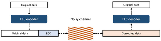
Figure 3.
Schematic of forward error correction (FEC).
2.4. Reed–Solomon (RS) Scheme
Since the proposed scheme is designed for nodes that communicate using the RS scheme among various FEC methods, this section describes this in more detail. The RS scheme is the most typical and efficient scheme among the FEC schemes. The blocks of the RS are composed of the payload and parity fields [21]. The original data that need to be transmitted are placed in the payload field, and the parity to restore errors is added in the parity field. Figure 4 illustrates the packet structure of the RS.
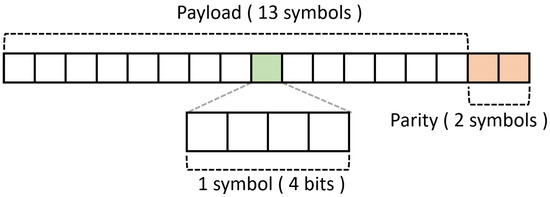
Figure 4.
Code-word of Reed–Solomon code (RS) (15,13) [41].
The blocks of the RS scheme have n symbols. If the payload consists of k symbols, the parity consists of symbols, which are typically denoted as RS. If an RS block consisting of n symbols is transmitted, the maximum number of symbols that can be recovered from the receiving node is [41,42,43]. Furthermore, when the symbol size of the RS code is m bits, the maximum size n of the code-word that it builds is symbols, or bits. Because the RS scheme essentially transmits parity bits which are piggybacked to the payload, additional energy consumption inevitably occurs. In addition, because parity is generated by encoding the payload of the original data, additional encoding and decoding energy is required at the transmitter and receiver, respectively. In summary, the RS scheme can increase communication reliability by using a longer parity; however, it consumes more energy for encoding, decoding, transmitting and receiving data packets.
3. Enhanced FEC Scheme for SP-WSN
In this section, we describe the energy state modeling and link state modeling methods in detail and explain the parity selection process to demonstrate the benefits of the proposed scheme. Thereafter, the various WSN applications to which the proposed scheme can be applied will be discussed.
3.1. Overview
Figure 5 shows the overview of the proposed scheme. This figure describes how the proposed scheme determines the appropriate parity size when node transfers data to node . In this figure, the energy that the node can use for FEC in addition to the basic operations is called the available energy.
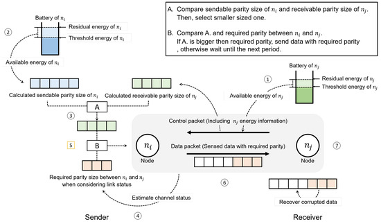
Figure 5.
Overview of proposed scheme.
- ①
- receives a control packet containing the available energy information of from node . Then, it calculates the maximum parity size which can deal with this available energy.
- ②
- calculates the maximum parity size which can be added with its own available energy.
- ③
- Select the smaller value by comparing the parity sizes determined in step ① and step ②; this value is the best parity size in terms of energy.
- ④
- estimates the channel state between itself and through the signal strength of control packet received during step ①; then, it calculates the parity size required for the current link state.
- ⑤
- Compare the parity size determined in step ③ with the parity size determined in step ④; if former is greater than the latter, data can be transmitted without error even if either value is finally selected. In the proposed scheme, however, the latter is selected as a final parity size to save energy. Meanwhile, in the opposite case (if the former is smaller than the latter), data transfer is abandoned in this round and delayed until the next round. This is because the errors are unlikely to be recovered even if data are transmitted by adding the maximum parity size available in terms of energy. This indicates a severe channel condition, and data transmission will be suspended until sufficient energy is available to send the data with the parity required for the link.
- ⑥
- transmits a data packet including the parity bits finally determined in step ⑤ to .
- ⑦
- recovers the error using parity bits included in the received data packet when the error is detected.
3.2. Energy Modeling
Solar energy may not always be available, and there is therefore a need to store the harvested energy using rechargeable batteries or low-powered supercapacitors, as shown in Figure 6. Based on this store-and-use type of energy model, Yang et al. [22] proposed an energy-threshold model to calculate the amount of surplus energy which can be used to improve various QoS of the WSN. This energy model is very useful and efficient since it is independent of weather, season, time and the type of battery. The proposed scheme is designed based on this energy model.
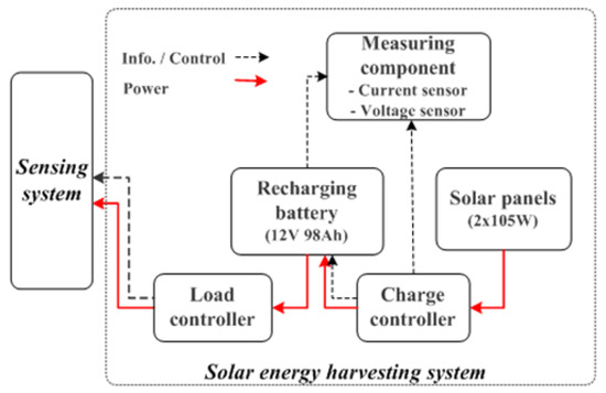
Figure 6.
A typical store-and-use architecture for a solar-energy-harvesting system.
Let be the residual energy of a node. Given the current , the expected time for a node to be fully charged is defined as follows:
where and are the moving average values of the harvested and consumed power of a node, respectively, and C is the total battery capacity. An important issue is that the average energy consumption rate should be lower than the average solar-energy harvest rate because the battery is only charged when the following inequality is satisfied:
Fortunately, although is not controllable, can be approximately controlled by adjusting the duty-cycle or sensing rate control. Therefore, we can satisfy Inequality (2) by employing a suitable system configuration. Since is the moving average of the harvested power rate of a node, it is not significantly affected by the fluctuation of the harvested power as time goes by. However, inequality (2) may not be satisfied at the beginning of sensor placement or when the amount of change is significantly large. This case means that there is no surplus energy to enhance QoS, so only the basic operation of the node is performed. Then, at the start of next cycle, the node is adjusted to satisfy inequality (2). In the worst case, even if is adjusted to be as low as possible, inequality (2) may not be satisfied due to the very small harvested power rate. In such a case, the node operates in sleep mode until inequality (2) is satisfied since there is a possibility of blackout even if only the basic operation of the node is performed.
For the node to remain available, it should have sufficient energy until the next time that the battery is full. Therefore, to live permanently, the node should satisfy the following condition:
Therefore, if the residual energy in the battery is at least , the node will not be blacked out; thus, we set this as the minimum energy threshold . Therefore, given the current remaining energy , the energy that can be additionally used without a blackout can be expressed as follows:
From now on, we will call the surplus energy.
3.3. Channel-Status Modeling
In a network environment, there are several indicators of channel conditions [44]. To estimate the amount of data with errors in the received data, our scheme uses the BER, which provides information regarding the percentage of bits for which an error has occurred in all the received data. In a wireless network, when transmitting and receiving data, a modulation and demodulation process is performed. For M-ary phase shift keying modulation, the BER, denoted as , is expressed as follows [45]:
where M is , when the size of a FEC symbol is k bits, and Q represents an error function with a Gaussian probability distribution [45]. is the energy per bit of the received signal, and is the noise power spectral density. As a result, represents the SNR per bit, and this can be derived from the strength of the received radio signal measured at the hardware level [46]. If the BER of the link between the transmitting and receiving nodes is estimated by the measured SNR and Equation (6), the amount of data for which errors occur in the received data can be estimated. Thus, the size of the parity required for successful communication can be predicted.
3.4. Parity Size Determination According to Residual Energy
In the RS scheme, the parity size determination is performed in consideration of the energy state of both the transmitting and receiving nodes because the larger the parity size, the greater the energy used to transceive data. Additionally, the amount of energy required for encoding and decoding is also proportional to the parity size. Therefore, the parity size should be determined, considering the energy required to transceive the data and the energy required for encoding and decoding the RS code [41,43].
- Parity size of the transmitting node in terms of energyThe energy consumed by the transmitting node to transmit the data is calculated as follows [47]:where is the size of the data to be transmitted, is the energy consumed when transmitting one bit to a distance of one meter, d is the transmission distance and represents the path loss, the default value of which is 2; this value varies depending on the environment. In the proposed scheme, the maximum parity size that can be transmitted without exceeding the available surplus energy , calculated in Equation (5), is estimated at the beginning of the time-slot.The energy that can be used to transmit the parity is calculated as follows:where is the amount of energy consumed to send original data in the payload field, and is the amount of energy used for encoding the RS code.Please note that a symbol which consists of m bits is an operation unit of the RS scheme for encoding and transmitting. Therefore, the maximum parity symbol size that can be sent with the energy of can be represented as follows:where m is the number of bits per symbol.
- Parity size of the receiving node in terms of energyThe RS scheme consumes energy for data decoding and recovery that cannot be ignored. Assuming that the transmitting node transmits data with a long parity, considering only its energy status, the receiving node may not decode it due to insufficient energy. Therefore, when determining the parity size, the node sending the data must consider the energy of the node receiving the data, as well as its own energy.Please note that if the receiving node consumes energy exceeding , it may be blacked out. Therefore, the receiving node must limit the parity size by calculating the size of the parity that can be handled with energy . The amount of energy consumed to receive parity, excluding the energy consumed to receive data and the decoding energy , is as follows:Therefore, the maximum number of parity symbols that can be received with can be calculated as follows:where is the energy consumed when receiving one bit of data.
- Parity size determination in terms of energyAt the start of the time-slot, the receiver node embeds the information of in a control packet and transmits it to the sender. Then, the sender compares and and selects the smaller of the two as the parity candidate .
3.5. Parity Size Determination According to Channel Condition
The BER is the ratio of received error bits to all the transmitted bits. The amount of data that may produce errors in the receiving node can be estimated as follows:
where is the size of the data that will be sent. By using , the size of the parity candidate required in the current channel state in symbol units can be calculated as follows:
As mentioned in Section 2.4, symbols can be restored for parity symbols. This is the reason for the multiplication by 2 in Equation (14).
3.6. Parity Size Selection and Data Transmission
If is satisfied, both the sender and receiver have sufficient energy to exchange the required size of the parity in the corresponding channel state. Therefore, the data are transmitted with a parity with the length .
Conversely, if < is satisfied, one party out of the sender and receiver does not have sufficient energy to handle the parity of . In this case, data transmission is suspended until the start of the next round to save energy, and the possibility of transmission is checked in the next transmission round. This is because, even if is used in the sender, the errors are unlikely to be recovered owing to the severe link quality.
Figure 7 briefly shows the benefit of the proposed scheme through the above process. The scheme can save energy when the channel quality is good and improve the recovery ability of data by using the energy that was previously saved when the channel condition is poor.
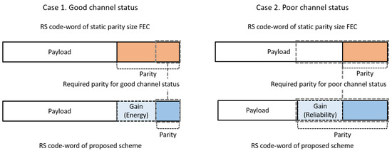
Figure 7.
Comparison with FEC using fixed parity.
3.7. Urgent Mode to Send Emergency Data
If the channel condition is so poor that it is useless to apply the possible parity size in terms of energy, a node suspends data transmission, as described above. Subsequently, when the energy of the sender and receiver is sufficiently harvested, the data are then transmitted. This method can be efficient for delay-tolerant applications, such as ecological monitoring or temperature and humidity detection in vast areas. However, it can cause a critical delay for transmitting important data in emergency applications, such as military operations or forest fire detection. Therefore, in the proposed scheme, emergency messages are assigned an urgent flag in the MAC header, as shown in Figure 8, leading to the model transmitting and receiving data regardless of the amount of energy; the nodes that receive the urgent message relay it immediately. By applying this method, the proposed scheme can be useful for more diverse WSN applications, including emergency data transmission.
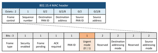
Figure 8.
Urgent mode flag bit in a MAC header.
3.8. Pseudo-Code of the Proposed Scheme
In this study, as described until now, the parity size that is used in the RS scheme is determined by considering the energy state of the sender and the receiver, as well as the channel condition between them, to reliably transmit data while maximizing the harvested solar-energy. Algorithms 1 and 2 describe the process of the proposed scheme.
| Algorithm 1: Operation of sending node i in 1 round |
 |
| Algorithm 2: Calculate of node i |
| ; ; ; return ; |
4. Performance Evaluation
4.1. Experiment Environment
We have evaluated the performance of the proposed scheme using Solar-Castalia [48], which is a simulator designed for SP-WSNs. The nodes were randomly deployed in an area with a size of . The weather is randomly selected from sunny, cloudy or rainy, and nodes obscured by naturally occurring shades are also considered. Communication specifications of the CC2630 RF module [49] developed for Zigbee and 6-LoWPAN were used. For the encoding and decoding energies, the values measured in previous studies [41,50] were used.
We compare our scheme with other schemes that use a fixed parity size of RS (31, 29) and RS (31, 21): the energy-aware RS (EA-RS) scheme [50], which operates in two modes, depending on the energy state; and the channel-status adaptive RS (CA-RS), which does not consider the energy state but dynamically selects parity according to the channel state. Table 3 presents the detailed parameters used in our simulation.
Table 3.
Simulation parameters. BER: bit-error rate.
4.2. Simulation Results
Figure 9 shows the blackout time of a node over time for 150 nodes with 0.15 BER. FEC consumes energy not only for the transmission of the data but also for encoding and decoding the data, which accounts for a significant part of the node’s energy consumption. For this reason, RS (31, 29), which uses two symbols as a parity, has the shortest blackout time. Since RS (31, 21) uses eight more parity symbols than RS (31, 29), the energy for encoding and decoding the data and for the transmission of the data increases accordingly. This results in a longer blackout time than the result of RS (31,21). EA-RS operates by selecting the RS (31, 21) mode and RS (31, 29) mode according to the energy state of the nodes. Therefore, it can be found that the blackout time of EA-RS is longer than that of RS (31, 29) and shorter than that of RS (31, 21). Because CA-RS determines the parity size according to the current channel condition, the parity size increases rapidly as the channel condition deteriorates. This can be found between the 9th and 15th days, which are rainy days, in Figure 9. Because the proposed scheme only uses the surplus energy and determines the parity size considering the energy state of both the sender and receiver, blackout does not occur at all.
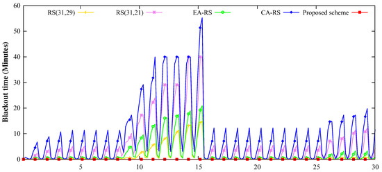
Figure 9.
Change in the blackout times, according to simulation time, for 150 nodes and 0.15 BER (9th∼15th day: rainy, 26th∼30th day: cloudy; others: sunny).
Figure 10 shows the amount of data collected from sink nodes over time for 150 nodes with 0.15 BER. Because the harvested solar energy changes over time, as shown in Figure 2, the energy that can be used for the data collection changes with the harvested solar energy. As can be inferred from Figure 10, the data for all the schemes are collected intensively at the time when plenty of energy is harvested. Because the transmission success rate is changed according to the difference between the size of the parity of each scheme, a noticeable difference can be found in the collected data. In particular, the difference between the amount of the collected data in the CA-RS and the proposed scheme is significant. Even though both schemes consider the channel states, the proposed scheme can collect more data at the sink node because the consideration of the energy status of both sender and receiver leads to a higher data reception rate than CA-RS.
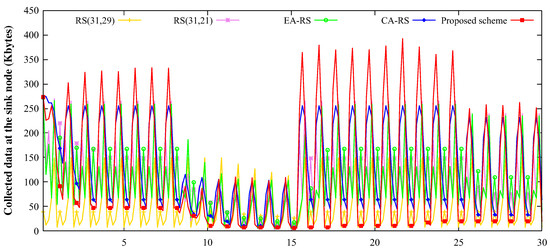
Figure 10.
Change in the collected data at the sink node, according to the simulation time for 150 nodes and 0.15 BER (9th∼15th day: rainy, 26th∼30th day: cloudy; others: sunny).
A hotspot region is one in which the flow of data across the WSN is concentrated, resulting in a significantly higher energy consumption and more frequent blackouts than other regions. Figure 11 shows the remaining energy of nodes in the hotspot around the sink node. In Figure 11, it can be observed that the amount of remaining energy of the schemes, except for the proposed scheme, decreases sharply between the 9th and 16th days, which are rainy days. In the proposed scheme, however, the nodes maintain a relatively high and stable energy level over time. Therefore, it can be inferred that the proposed scheme successfully manipulates the amount of energy consumed.
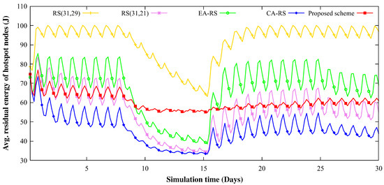
Figure 11.
Energy change of hotspot region nodes according to an experiment time for 150 nodes and 0.15 BER (9th∼15th day: rainy, 26th∼30th day: cloudy; others: sunny).
Figure 12 and Figure 13 show the blackout time measured in the overall topology and the amount of data collected from the sink nodes, respectively, when the numbers of nodes deployed are 100, 125 and 150. Because the amount of data transmission and reception increases with the increased number of nodes, the energy consumption in each node also increases. For this reason, the blackout time also increases as the number of nodes increases. However, as mentioned earlier, the proposed scheme only consumes surplus energy; thus, blackout does not occur. Consequently, the nodes in the proposed scheme can collect a large amount of data without losing it. As can be observed in the figure, even if the number of nodes varies, the proposed scheme shows the highest amount of data collected from the sink node.
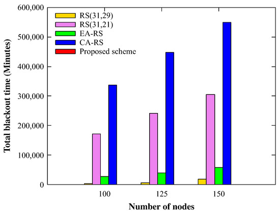
Figure 12.
Total number of blackout nodes with various node counts (BER 0.15).
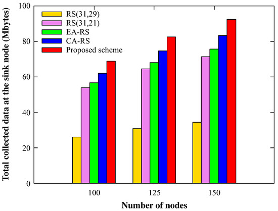
Figure 13.
Total amount of received data at the sink node with various node counts (BER 0.15).
Figure 14 shows the change in total blackout time when the BER is changed to 0.05, 0.1, 0.15 and 0.2. In the RS (31, 29) and RS (31, 21) schemes, which use fixed parity, the blackout time is reduced as the channel condition deteriorates. This occurs because, for a higher BER, most of the data transfer is likely to be deferred, and thus the data reception rate is reduced, resulting in decreased amounts of data being relayed throughout the network. As a result, lower energy for transmitting, decoding, and encoding the data is consumed; therefore, the high BER induces a shorter blackout time in fixed parity schemes. Because EA-RS sends data with two or 10 parity symbols, depending on the energy state, it does not adopt a fully flexible parity size. Therefore, it shows a similar result to the previous two schemes. CA-RS uses a longer parity as the BER increases, which consumes more energy, resulting in an increased blackout time. The proposed scheme also uses parity according to the BER; however, because the energy state of the nodes is simultaneously considered, no blackout occurs.
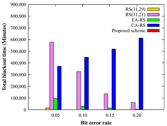
Figure 14.
Blackout during entire time for varying BER (node 150).
Figure 15 shows the total amount of data collected at the sink node, under the same conditions as Figure 14. This figure indicates that all the schemes show that the collected data decreases as the BER increases, which is inferred because the number of errors have exceeded the recovery limit of the RS scheme. As the BER increases, CS-RS tries to enhance the error recovery rate by increasing the parity size but inevitably consumes more energy. Thus, fewer data are collected than the proposed scheme. The proposed scheme shows the best results considering both the channel condition and energy consumption, regardless of the BER.
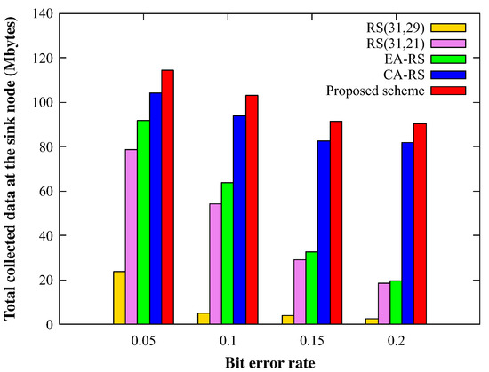
Figure 15.
Received data of sink for varying BER (node 150).
5. Conclusions
The goal of SP-WSN is to efficiently use periodically collected energy. For FEC, the data recovery rate increases with the length of the parity, and there is a trade-off between the length of the parity and energy consumption. In this study, for the most efficient use of solar energy, the proposed scheme uses the surplus energy to enhance the error recovery rate. In each node with the proposed scheme, the length of the parity symbol, which is used to recover the error data, is determined by considering both the link status and the energy status of the sender and receiver nodes. In addition, if the parity length in terms of energy is not sufficiently long to handle the severe link condition, the node delays the transmission during this round until a sufficiently long parity can be generated with sufficient energy. As a result of comparing its performance with other schemes, it can be confirmed that the proposed scheme effectively prevents node blackout and collects more data than other schemes. In summary, the proposed scheme effectively improved the reliability of communication by optimally using harvested energy.
Author Contributions
G.W.G. and D.K.N. conceived this scheme; G.W.G. and M.K. designed and performed the experiments; I.Y., Y.K., and D.K.N. analyzed the data; and the manuscript was written by I.Y., Y.K., and D.K.N. and commented on by all the authors. All authors have read and agreed to the published version of the manuscript.
Funding
This research was partly supported by Basic Science Research Program through the National Research Foundation of Korea(NRF) funded by the Ministry of Education(NRF-2018R1D1A1B07045972) and by the MSIT(Ministry of Science and ICT), Korea, under the ITRC(Information Technology Research Center) support program(IITP-2020-2020-0-01602) supervised by the IITP(Institute for Information & Communications Technology Planning & Evaluation).
Conflicts of Interest
The authors declare no conflict of interest.
References
- Jovanovska, E.M.; Davcev, D. No pollution Smart City Sightseeing Based on WSN Monitoring System. In Proceedings of the 2020 IEEE Sixth International Conference on Mobile and Secure Services (MobiSecServ), Miami Beach, FL, USA, 22–23 February 2020; pp. 1–6. [Google Scholar]
- Adame, T.; Bel, A.; Carreras, A.; Melia-Segui, J.; Oliver, M.; Pous, R. CUIDATS: An RFID–WSN hybrid monitoring system for smart health care environments. Future Gener. Comput. Syst. 2018, 78, 602–615. [Google Scholar] [CrossRef]
- Caicedo-Ortiz, J.G.; De-La Hoz-Franco, E.; Ortega, R.M.; Piñeres-Espitia, G.; Combita-Niño, H.; Estévez, F.; Cama-Pinto, A. Monitoring system for agronomic variables based in WSN technology on cassava crops. Comput. Electron. Agric. 2018, 145, 275–281. [Google Scholar] [CrossRef]
- Behera, T.M.; Mohapatra, S.K.; Samal, U.C.; Khan, M.S.; Daneshmand, M.; Gandomi, A.H. I-sep: An improved routing protocol for heterogeneous WSN for IoT-based environmental monitoring. IEEE Internet Things J. 2019, 7, 710–717. [Google Scholar] [CrossRef]
- Tokala, M.; Nallamekala, R. Secured algorithm for routing the military field data using dynamic sink: Wsn. In Proceedings of the IEEE 2018 Second International Conference on Inventive Communication and Computational Technologies(ICICCT), Coimbatore, India, 20–21 April 2018; pp. 471–476. [Google Scholar]
- Saini, A.; Kansal, A.; Randhawa, N.S. Minimization of energy consumption in WSN using hybrid WECRA approach. Procedia Comput. Sci. 2019, 155, 803–808. [Google Scholar] [CrossRef]
- Wang, F.; Liu, W.; Wang, T.; Zhao, M.; Xie, M.; Song, H.; Li, X.; Liu, A. To reduce delay, energy consumption and collision through optimization duty-cycle and size of forwarding node set in WSNs. IEEE Access 2019, 7, 55983–56015. [Google Scholar] [CrossRef]
- Dhami, M.; Garg, V.; Randhawa, N.S. Enhanced lifetime with less energy consumption in WSN using genetic algorithm based approach. In Proceedings of the 2018 IEEE 9th Annual Information Technology, Electronics and Mobile Communication Conference (IEMCON), Vancouver, BC, Canada, 1–3 November 2018; pp. 865–870. [Google Scholar]
- Sudevalayam, S.; Kulkarni, P. Energy harvesting sensor nodes: Survey and implications. IEEE Commun. Surv. Tutor. 2010, 13, 443–461. [Google Scholar] [CrossRef]
- Chen, Q.; Gao, H.; Cai, Z.; Cheng, L.; Li, J. Energy-collision aware data aggregation scheduling for energy harvesting sensor networks. In Proceedings of the IEEE INFOCOM 2018-IEEE Conference on Computer Communications, Honolulu, HI, USA, 16–19 April 2018; pp. 117–125. [Google Scholar]
- Gaglione, A.; Rodenas-Herraiz, D.; Jia, Y.; Nawaz, S.; Arroyo, E.; Mascolo, C.; Soga, K.; Seshia, A.A. Energy neutral operation of vibration energy-harvesting sensor networks for bridge applications. In Proceedings of the 2018 International Conference on Embedded Wireless Systems and Networks (EWSN), Madrid, Spain, 14–16 February 2018. [Google Scholar]
- Raghunathan, V.; Kansal, A.; Hsu, J.; Friedman, J.; Srivastava, M. Design considerations for solar energy harvesting wireless embedded systems. In Proceedings of the IPSN 2005, IEEE Fourth International Symposium on Information Processing in Sensor Networks, Boise, ID, USA, 15 April 2005; pp. 457–462. [Google Scholar]
- Li, K.; Yuen, C.; Kusy, B.; Jurdak, R.; Ignjatovic, A.; Kanhere, S.S.; Jha, S. Fair scheduling for data collection in mobile sensor networks with energy harvesting. IEEE Trans. Mob. Comput. 2018, 18, 1274–1287. [Google Scholar] [CrossRef]
- Basagni, S.; Naderi, M.Y.; Petrioli, C.; Spenza, D.; Conti, M.; Giordano, S.; Stojmenovic, I. Wireless sensor networks with energy harvesting. In Mobile Ad Hoc Networking: Cutting Edge Directions; Basagni, S., Conti, M., Giordano, S., Stojmenovic, I., Eds.; John Wiley & Sons, Inc.: Hoboken, NJ, USA, 2013; pp. 703–736. [Google Scholar]
- Qi, N.; Dai, K.; Yi, F.; Wang, X.; You, Z.; Zhao, J. An adaptive energy management strategy to extend battery lifetime of solar powered wireless sensor nodes. IEEE Access 2019, 7, 88289–88300. [Google Scholar] [CrossRef]
- Raghunathan, V.; Schurgers, C.; Park, S.; Srivastava, M.B. Energy-aware wireless microsensor networks. IEEE Signal Process. Mag. 2002, 19, 40–50. [Google Scholar] [CrossRef]
- Akyildiz, I.F.; Su, W.; Sankarasubramaniam, Y.; Cayirci, E. Wireless sensor networks: A survey. Comput. Netw. 2002, 38, 393–422. [Google Scholar] [CrossRef]
- Tian, Z.; Yuan, D.; Liang, Q. Energy efficiency analysis of error control schemes in wireless sensor networks. In Proceedings of the 2008 IEEE International Wireless Communications and Mobile Computing Conference, Crete Island, Greece, 6–8 August 2008; pp. 401–405. [Google Scholar]
- Abughalieh, N.; Steenhaut, K.; Nowé, A. Low power channel coding for wireless sensor networks. In Proceedings of the 2010 17th IEEE Symposium on Communications and Vehicular Technology in the Benelux (SCVT2010), Enschede, The Netherlands, 24–25 November 2010; pp. 1–5. [Google Scholar]
- Angelin, A.; Revathi, B.; Gayathri, T.; Balakumaran, M.D. Channel coding in WSN for energy optimization. Int. J. Adv. Res. Electr. Electron. Instrum. Eng. 2014, 3, 7873–7878. [Google Scholar]
- Reed, I.S.; Solomon, G. Polynomial codes over certain finite fields. J. Soc. Ind. Appl. Math. 1960, 8, 300–304. [Google Scholar] [CrossRef]
- Yang, Y.; Wang, L.; Noh, D.K.; Le, H.K.; Abdelzaher, T.F. Solarstore: Enhancing data reliability in solar-powered storage-centric sensor networks. In Proceedings of the 7th International Conference on Mobile Systems, Applications, and Services, Krakow, Poland, 22 June 2009; pp. 333–346. [Google Scholar]
- Nolan, K.E.; Guibene, W.; Kelly, M.Y. An evaluation of low power wide area network technologies for the Internet of Things. In Proceedings of the 2016 IEEE International Wireless Communications and Mobile Computing Conference (IWCMC), Paphos, Cyprus, 5–9 September 2016; pp. 439–444. [Google Scholar]
- Petäjäjärvi, J.; Mikhaylov, K.; Pettissalo, M.; Janhunen, J.; Iinatti, J. Performance of a low-power wide-area network based on LoRa technology: Doppler robustness, scalability, and coverage. Int. J. Distrib. Sens. Netw. 2017, 13. [Google Scholar] [CrossRef]
- Wang, S.Y.; Chen, Y.R.; Chen, T.Y.; Chang, C.H.; Cheng, Y.H.; Hsu, C.C.; Lin, Y.B. Performance of LoRa-based IoT applications on campus. In Proceedings of the IEEE Vehicular Technology Conference, Toronto, ON, Canada, 24–27 September 2017; pp. 1–6. [Google Scholar]
- Raza, U.; Kulkarni, P.; Sooriyabandara, M. Low power wide area networks: An overview. IEEE Commun. Surv. Tutor. 2017, 19, 855–873. [Google Scholar] [CrossRef]
- Prauzek, M.; Konecny, J.; Borova, M.; Janosova, K.; Hlavica, J.; Musilek, P. Energy harvesting sources, storage devices and system topologies for environmental wireless sensor networks: A review. Sensors 2018, 18, 2446. [Google Scholar] [CrossRef]
- Adu-Manu, K.S.; Adam, N.; Tapparello, C.; Ayatollahi, H.; Heinzelman, W. Energy-Harvesting Wireless Sensor Networks (EH-WSNs) a Review. ACM Trans. Sens. Netw. (TOSN) 2018, 14, 1–50. [Google Scholar] [CrossRef]
- Sharma, H.; Haque, A.; Jaffery, Z.A. Solar energy harvesting wireless sensor network nodes: A survey. J. Renew. Sustain. Energy 2018, 10, 023704. [Google Scholar] [CrossRef]
- Engmann, F.; Katsriku, F.A.; Abdulai, J.D.; Adu-Manu, K.S.; Banaseka, F.K. Prolonging the lifetime of wireless sensor networks: A review of current techniques. Wirel. Commun. Mob. Com. 2018, 2018. [Google Scholar] [CrossRef]
- Ottman, G.K.; Hofmann, H.F.; Bhatt, A.C.; Lesieutre, G.A. Adaptive piezoelectric energy harvesting circuit for wireless remote power supply. IEEE Trans. Power Electron. 2002, 17, 669–676. [Google Scholar] [CrossRef]
- Sodano, H.A.; Inman, D.J.; Park, G. Comparison of piezoelectric energy harvesting devices for recharging batteries. J. Intell. Mater. Syst. Struct. 2005, 16, 799–807. [Google Scholar] [CrossRef]
- Simjee, F.I.; Chou, P.H. Efficient charging of supercapacitors for extended lifetime of wireless sensor nodes. IEEE Trans. Power Electron. 2008, 23, 1526–1536. [Google Scholar] [CrossRef]
- Yoon, I.; Kim, H.; Noh, D.K. Adaptive data aggregation and compression to improve energy utilization in solar-powered wireless sensor networks. Sensors 2017, 17, 1226. [Google Scholar] [CrossRef] [PubMed]
- Kang, M.; Yoon, I.; Noh, D.K. Efficient location service for a mobile sink in solar-powered wireless sensor networks. Sensors 2019, 19, 272. [Google Scholar] [CrossRef] [PubMed]
- Tunca, C.; Isik, S.; Donmez, M.Y.; Ersoy, C. Ring routing: An energy-efficient routing protocol for wireless sensor networks with a mobile sink. IEEE Trans. Mob. Comput. 2014, 14, 1947–1960. [Google Scholar] [CrossRef]
- Hamming, R.W. Error detecting and error correcting codes. Bell Syst. Tech. J. 1950, 29, 147–160. [Google Scholar] [CrossRef]
- Costello, D.J. Error Control Coding: Fundamentals and Applications; Prentice Hall: Upper Saddle River, NJ, USA, 1983. [Google Scholar]
- Bose, R.C.; Ray-Chaudhuri, D.K. On a class of error correcting binary group codes. Inf. Control 1960, 3, 68–79. [Google Scholar] [CrossRef]
- Berrou, C.; Glavieux, A.; Thitimajshima, P. Near Shannon limit error-correcting coding and decoding: Turbo-codes.1. In Proceedings of the ICC’93—IEEE International Conference on Communications, Geneva, Switzerland, 23–26 May 1993; Volume 2, pp. 1064–1070. [Google Scholar]
- Ahn, J.S.; Yoon, J.H.; Lee, K.W. Performance and energy consumption analysis of 802.11 with FEC codes over wireless sensor networks. J. Commun. Netw. 2007, 9, 265–273. [Google Scholar] [CrossRef]
- Wicker, S.B.; Bhargava, V.K. Reed-Solomon Codes and Their Applications; John Wiley & Sons: Hoboken, NJ, USA, 1999. [Google Scholar]
- Jung, K.K.; Choi, W.S. Performance Analysis of RS codes for Low PowerWireless Sensor Networks. J. Korea Soc. Comput. Inf. 2010, 15, 83–90. [Google Scholar] [CrossRef]
- Baccour, N.; Koubâa, A.; Mottola, L.; Zúñiga, M.A.; Youssef, H.; Boano, C.A.; Alves, M. Radio link quality estimation in wireless sensor networks: A survey. ACM Trans. Sens. Netw. (TOSN) 2012, 8, 1–33. [Google Scholar] [CrossRef]
- Rappaport, T.S. Wireless Communications: Principles and Practice; Prentice Hall: Upper Saddle River, NJ, USA, 1996; Volume 2. [Google Scholar]
- Zhang, J.; Tan, K.; Zhao, J.; Wu, H.; Zhang, Y. A practical SNR-guided rate adaptation. In Proceedings of the IEEE INFOCOM 2008—The 27th Conference on Computer Communications, Phoenix, AZ, USA, 13–18 April 2008; pp. 2083–2091. [Google Scholar]
- Melodia, T.; Pompili, D.; Akyildiz, I.F. Optimal local topology knowledge for energy efficient geographical routing in sensor networks. In Proceedings of the IEEE INFOCOM 2004, Hong Kong, China, 7–11 March 2004; Volume 3, pp. 1705–1716. [Google Scholar]
- Yi, J.M.; Kang, M.J.; Noh, D.K. SolarCastalia: Solar energy harvesting wireless sensor network simulator. Int. J. Distrib. Sens. Netw. 2015, 11, 415174. [Google Scholar] [CrossRef]
- TI CC2630. CC2630 SimpleLink™ 6LoWPAN, ZigBee® Wireless MCU Datasheet (Rev. B). Apr. 2017. Available online: http://www.ti.com/product/CC2630 (accessed on 31 July 2020).
- Jung, J.; Kang, M.; Yoon, I.; Noh, D.K. Adaptive forward error correction scheme to improve data reliability in solar-powered wireless sensor networks. In Proceedings of the 2016 IEEE International Conference on Information Science and Security (ICISS), Pattaya, Thailand, 19–22 December 2016; pp. 1–4. [Google Scholar]
© 2020 by the authors. Licensee MDPI, Basel, Switzerland. This article is an open access article distributed under the terms and conditions of the Creative Commons Attribution (CC BY) license (http://creativecommons.org/licenses/by/4.0/).